
Komatsu Wheel Loader WA470, WA480 Repair Service Manual
Complete service repair manual with Electrical Wiring Diagrams for Komatsu Wheel Loader WA470, WA480, with all the technical information to maintain, diagnose, repair, rebuild like professional mechanics.
Komatsu Wheel Loader WA470, WA480 workshop service repair manual includes:
* Numbered table of contents easy to use so that you can find the information you need fast.
* Detailed sub-steps expand on repair procedure information
* Numbered instructions guide you through every repair procedure step by step.
* Troubleshooting and electrical service procedures are combined with detailed wiring diagrams for ease of use.
* Notes, cautions and warnings throughout each chapter pinpoint critical information.
* Bold figure number help you quickly match illustrations with instructions.
* Detailed illustrations, drawings and photos guide you through every procedure.
* Enlarged inset helps you identify and examine parts in detail.
PRODUCT DETAILS:
Total Pages: 9,846 pages
File Format: PDF (Internal Links, Bookmarked, Table of Contents, Searchable, Printable, high quality)
Language: English
CEAM009103 - Wheel Loader WA480-6 Operation & Maintenance Manual.pdf
CEAM023602 - Wheel Loader WA480-6 Operation & Maintenance Manual.pdf
CEBM007102 - Wheel Loader WA470-6, WA480-6 Shop Manual.pdf
CEBM023002 - Wheel Loader WA470-6, WA480-6 Shop Manual.pdf
SEBM024414 - Wheel Loader WA470-5, WA480-5 Shop Manual
SEN00783-07 - Wheel Loader WA470-6, WA480-6 Shop Manual.pdf
SEN04409-06 - Wheel Loader WA470-6, WA480-6 Shop Manual.pdf
VEBM946101 - Wheel Loader WA470-6, WA480-6 Shop Manual.pdf
MAIN SECTIONS
CEAM009103 - Wheel Loader WA480-6 Operation & Maintenance Manual......2
CEAM009103......2
FOREWORD......5
SAFETY INFORMATION......6
APPROVED AND NON-APPROVED USES......7
Approved Functions......7
Non-Approved Functions......7
VISIBILITY STANDARD......8
Visibility in Immediate Area......8
12-M Radius Visibility......8
Front/Rear, Left/Right Directions of Machine......9
Machine Serial Number/Product Identification Number (PIN)......10
Engine Serial Number, EPA Regulations......10
Position of Service Meter......11
Serial Numbers and Dealer Information......12
TABLE OF CONTENTS......13
SAFETY AND WARNING DECALS......27
Location of Safety Decals......27
Safety Labels......28
GENERAL SAFETY RULES AND PRECAUTIONS......35
General Safety Rules......35
General Safety at Job Site......36
Working on Loose Ground......36
Safety Features......37
Personal Protective Equipment......37
Keep Machine Clean......37
Fire and Explosion Prevention......38
Fire Caused by Fuel, Oil, Antifreeze, or Window Washer Fluid......38
Fire Caused by Accumulation of Flammable Material......38
Fire Coming from Electric Wiring......39
Fire Coming from Hydraulic Line......39
Windshield Washer Fluid......39
Action If Fire Occurs......39
Fire Extinguisher and First Aid Kit......39
Fire Prevention and Suppression......40
Fire Prevention Steps......40
Fixed Fire Detection System......40
Fixed Fire Suppression System......40
Fire Prevention Procedures......40
Precautions When Cleaning Cab Glass......41
Dust Hazards Precautions......42
Keep Operator's Cab Clean......42
Unauthorized Modifications......42
Leaving Operators Compartment......43
Mounting and Dismounting......44
Crush or Pinch Point Dangers......44
Inside Operators Compartment......45
Precautions When Using ROPS......45
Emergency Escape From Operator's Cab......45
PRECAUTIONS BEFORE STARTING OPERATIONS......46
Pre-Operational Checks......46
Starting Your Work Operations......46
Seat Belt Inspection......47
Work Site Hazards......48
Avoiding Dangerous Situations......49
Working Clearances......51
Operating on Snow or Icy Surfaces......51
Precautions in Cold Areas......52
Asbestos Hazard Alert......52
RULES FOR ROAD TRAVEL......53
Traveling in Reverse......53
Travel on Slopes......54
Parking the Machine......55
PRECAUTIONS DURING MAINTENANCE OPERATIONS......56
Warning Tags......56
Equipment Storage......56
Working Under the Machine......57
Using Drop Lamps......57
Keeping the Machine Clean......57
HANDLING TIRES......58
Precautions When Storing Tires......58
PERFORMING GENERAL MAINTENANCE PROCEDURES......59
Running the Engine During Maintenance......61
Proper Tools......62
Engine System High-Voltage......62
Welding, Grinding or Cutting......63
When Using Hammer......63
Refueling the Machine......64
Cooling System Precautions......64
Battery Precautions......65
Starting the Machine......66
High-Pressure Hoses......66
Safety Handling High-Pressure Hoses......66
Precaution For High Fuel Pressure......67
High Temperature Areas......67
Disposal of Waste Materials......67
Inflating Tires......68
Accumulator......68
Critical Parts......68
TRANSPORTING THE MACHINE......69
Loading and Unloading a Trailer......69
Loading Machine......70
TOWING THE MACHINE......71
GENERAL VIEW......75
General View Of Machine......75
General View of Controls and Gauges......76
Machine Monitor......77
Switch Panel......79
EXPLANATION OF COMPONENTS......80
Machine Monitor......80
Types of Warnings......81
Emergency Stop......81
Caution......81
Mistaken Operation......81
Inspection and Maintenance......81
Central Warning Lamp......81
Character Display Portion......82
Service Meter......82
Action Code Display......83
Failure Code Display......84
Filter, Oil Replacement Time Display......85
Emergency Stop Items......87
Brake Oil Pressure Caution Lamp......88
Engine Oil Pressure Caution Lamp......88
Battery Charge Circuit Caution Lamp......89
Steering Oil Pressure Caution Lamp (if equipped)......89
Caution Items......90
Brake Oil Temperature Caution Lamp......91
Torque Converter Oil Temperature Caution Lamp......91
Engine Coolant Temperature Caution Lamp......92
Hydraulic Oil Temperature Caution Lamp......92
Fuel Level Caution Lamp......92
Inspection and Maintenance Items......93
Radiator Coolant Level Caution Lamp......93
Engine Oil Level Caution Lamp......94
Battery Electrolyte Level Caution Lamp......94
Maintenance Caution Lamp......94
Air Cleaner Clogging Caution Lamp......95
Water Separator Caution Lamp......95
Transmission Oil Filter Clogging Caution Lamp......95
Pilot Display Portion......96
Parking Brake Pilot Lamp......97
Cooling Fan Reverse Rotation Pilot Lamp......97
Emergency Steering Pilot Lamp......97
Power Mode Pilot Lamp (P Mode)......98
Preheating Pilot Lamp......98
Semi-Auto Digging Pilot Lamp......98
Auto-Greasing Pilot Lamp......98
Joystick Pilot Lamp (if equipped)......98
Directional Selector Pilot Lamp......98
Economy Operation Display Lamp......99
Shift Indicator......99
Auto-Shift Pilot Lamp......99
Torque Converter Lockup Pilot Light (if equipped)......99
Shift Hold Pilot Lamp......100
Shift Lever Position Pilot Lamp......100
Turn Signal Pilot Lamp......100
Head Lamp High-Beam Pilot Lamp......100
Meter Display Portion......101
Torque Converter Oil Temperature Gauge......101
Engine Coolant Temperature Gauge......102
Hydraulic Temperature Gauge......102
Fuel Gauge......102
Speedometer......103
Meter Display Pilot Lamp......103
OTHER FUNCTIONS OF MACHINE MONITOR......104
Overall Menu......104
Displaying Odometer......105
Resetting Filter, Oil Replacement Time......105
Entering Telephone Number......106
Selecting Language......107
Adjusting Monitor Brightness......109
Switching Travel Speed/Engine Speed Display......111
Switching Travel Speed/Engine Speed Display/Non-Display......112
SWITCHES AND CONTROLS......113
General View......113
Ignition Switch......114
Power Mode Selector Switch......115
Transmission Shift Mode Selector Switch......115
Transmission Cutoff Switch......116
Transmission Cutoff Set Switch......116
Lamp Switch......117
Turn Signal Lever......117
Dimmer Switch......117
Horn Button......118
Hazard Lamp Switch......118
Parking Brake Switch......119
Front Working Lamp Switch......119
Rear Working Lamp Switch......120
Machine Monitor Mode Selector Switch 1......120
Machine Monitor Mode Selector Switch 2......120
Kickdown Switch......121
Hold Switch......122
Front Wiper Switch......122
Rear Wiper Switch......122
Cigarette Lighter......123
Room Lamp Switch......123
Rear Heated Wire Glass Switch......123
ECSS Switch......124
Emergency Steering Switch (if equipped)......124
Cooling Fan Reverse Rotation Switch (If Equipped)......125
Cooling Fan Auto-Reverse Rotation Switch (If Equipped)......125
Conditions for Switching Fan Rotation......126
Torque Converter Lockup Switch (if equipped)......128
CONTROL LEVERS, PEDALS......129
General View......129
Gearshift Lever......129
Manual Shift......129
Automatic Shift......130
Directional Lever......131
Gearshift Lever Stopper......131
Work Equipment Lock Lever......132
Bucket Control Lever......132
Lift Arm Control Lever......133
Brake Pedals......134
Accelerator Pedal......134
SECURITY LOCKS AND SAFETY FEATURES......135
Steering Tilt Lock Lever......135
Frame Lock Bar......135
Cap with Lock......136
Fuel Tank Filler Port Cap......136
Back-Up Alarm......136
MACHINE FEATURES......137
Towing Pin......137
Grease Pump......137
Cab Door......138
Emergency Escape Right Door......138
Left Cab Door, Door Open Lock......140
Left Cab Door, Knob......141
Left Cab Door, Handle......141
Left Cab Sliding Window (Lock Release Knob)......141
Cab Wiper......142
ELECTRICAL......143
Power Outlet......143
Fuses......143
Fuse Capacity and Name of Circuit......144
Slow-Blow Fuse......145
WORK OPERATIONS......146
Walk-Around Check......146
Precautions Before Starting Work Operations......146
Check Before Starting Engine......150
Check Machine Monitor......150
Check Coolant Level, Add Coolant......151
Check Oil Level in Engine Oil Pan, Add Oil......152
Check Water Separator, Drain Water......153
Check Air Cleaner......154
Electric Air Cleaner Clogging Sensor......154
Check Fuel Level, Add Fuel......155
Check Electric Wiring......156
Check Inflation Pressure of Tires......156
Check Condition of Window Washer Spray......156
Check Wiping Efficiency of Wiper......156
Check Horn......156
Check Defroster Function......157
Check Locks......157
Check Emergency Exit......157
Adjustments......159
Adjusting Seat......159
Removing or Installing Headrest......161
Adjusting Seat Belt......162
Adjusting Lever Stand......163
Adjusting Mirrors......164
Final Checks Before Starting Engine......165
Starting Engine......167
Normal Starting......167
Starting in Cold Weather......169
Automatic Warming-Up Operation......170
Operations and Checks After Starting Engine......171
Checks After Starting Engine......171
Breaking in the Machine......172
Normal Operation......172
Stopping Engine......174
Check After Stopping Engine......174
Moving the Machine (Directional, Speed), Stopping the Machine......175
Moving the Machine......175
Changing Gear Speed......178
Changing Direction......179
Automatic Shift......180
Stopping the Machine......181
Transmission Cut-Off Function......182
Adjusting Transmission Cut-Off Position......183
Canceling Transmission Cut-Off Position......183
Stopping When Transmission Cut-Off Is On......183
Turning......184
Emergency Steering (if equipped)......185
Emergency Steering Self-Check Function......186
Operation of Work Equipment......187
Work Equipment Lock Lever......187
Lift Arm Control lever......187
Bucket Control Lever......188
Work Possible Using Wheel Loader......189
Digging Operations......189
Loading Piled Soil or Blasted Rock......189
Digging and Loading on Level Ground......191
Leveling Operations......192
Pushing Operations......192
Load and Carry Operations......192
Precautions for Using Load and Carry Method......192
Loading Operations......193
Cross-Drive Loading......193
V-Shape Loading......194
Precautions When Piling Up Loads......194
Preparations for Loading, Gathering Rocks......194
Approaching Facing......195
Digging......196
Traveling in Reverse After Excavation......197
Approaching Dump Truck......198
Loading Dump Truck......199
Reversing Away From Dump Truck......200
Precautions During Work Operations......201
Piling Up Loads......201
Handling Blasted Rock......201
Loosened Boulders......205
Pit Excavation......205
Cutting Face Operations......205
Switching Between Forward and Reverse......205
Turning When Tires Are Stationary......206
If Wheel Brake Does Not Work......206
Permissible Water Depth......206
Lower the Center of Gravity when Turning......206
Driving Up or Down Slopes......206
Driving the Machine......207
Braking Function......208
Adjusting Work Equipment......209
Bucket Level Indicator......209
Adjusting Boom Kick-Out......210
Adjusting Bucket Positioner......211
Measuring Dump Angle......212
Measuring Bucket Dump Angle......212
Measuring Coupler Dump Angle......215
Parking the Machine......218
Checks After Completion of Operation......220
Before Stopping Engine......220
After Stopping Engine......220
Locking the Machine......221
HANDLING TIRES......223
Precautions When Handling Tires......223
Tire Pressure......224
TRANSPORTATION......225
Transportation Procedure......225
Loading and Unloading Trailers......226
Loading Machine......226
Securing Machine......227
Unloading Machine......229
LIFTING MACHINE......230
Lifting Position......230
Lifting Procedure......230
COLD WEATHER OPERATION......232
Precautions for Low Temperature......232
Fuel and Lubricants......232
Coolant......232
Battery......233
Precautions After Completion of Work......233
After Cold Weather......233
LONG-TERM STORAGE......234
Before Storage......234
During Storage......234
After Storage......234
AUTOMATIC AIR CONDITIONER......235
Control Panel......235
Main Power Switch......236
Fan Switch......236
Air Conditioner Switch......237
Auto Switch......238
Temperature Switch......238
FRESH/RECIRC Selector Switch......238
Mode Selector Switch......239
Method of Operation......240
Cooling Operation......240
Heating Operation......240
Drying-Heating and Demisting Operation......241
When Not Using the Air Conditioner Regularly......241
Precautions When Using Air Conditioner......241
Inspection and Maintenance......241
Cool Box......242
KOMTRAX......243
Basic Precautions......243
TROUBLESHOOTING......244
When Machine Runs Out of Fuel......244
Towing the Machine......244
When Engine Can Be Used......245
When Engine Cannot Be Used......245
Releasing Parking Brake......246
Emergency Travel Operation......248
If Battery is Discharged......249
Precautions......249
Removal and Installation of Battery......249
Precautions for Charging Battery......250
Starting Engine With Booster Cables......251
Precautions When Connecting or Disconnecting Booster Cable......251
Connecting Booster Cable......251
Starting Engine......252
Disconnecting Booster Cable......252
Lowering Work Equipment When Engine Has Stopped......253
Other Troubleshooting......254
Electrical System......254
Chassis......255
Engine......257
GUIDES TO MAINTENANCE......261
Check Service Meter......261
Komatsu Genuine Replacement Parts......261
Komatsu Genuine Oils......261
Always Use Clean Washer Fluid......261
Always Use Clean Oil And Grease......261
Checking For Foreign Materials In Drained Oil And On Filters......261
Fuel Strainer......261
Welding Instructions......261
Do Not Drop Things Inside Machine......262
Dusty Work Sites......262
Avoid Mixing Oil......262
Locking Inspection Covers......262
Bleeding Air From Hydraulic Circuit......262
Precautions When Installing Hydraulic Hoses......262
Checks After Inspection and Maintenance......263
OUTLINES OF SERVICE......264
Handling Oil, Fuel, Coolant, And Performing Oil Clinic......264
Oil......264
Fuel......265
Coolant and Water for Dilution......265
Grease......266
Storing Oil and Fuel......266
Filters......266
Performing KOWA (Komatsu Oil Wear Analysis)......267
KOWA Analysis Items......267
Oil Sampling......267
Outline of Electric System......268
WEAR PARTS......269
Wear Parts List......269
RECOMMENDED FUEL, COOLANT, AND LUBRICANT......270
Fuel, Coolant, and Lubricant Ambient Temperature Chart......271
Recommended Brands, Other Than Komatsu Genuine Oil......272
Biodiesel Usage......273
Biodiesel Recommendation for Komatsu Engines......273
Biodiesel Terminology......273
Certification and Standards......274
Warranty and Use of Biodiesel Fuel in Komatsu Engines......274
Requirements for Using Biodiesel Fuel in Komatsu Engines......274
Properties of Biodiesel......275
Komatsu Biodiesel Blend Specification for B5 to B20......276
Summary of Recommendations......277
STANDARD TIGHTENING TORQUES FOR BOLTS AND NUTS......278
Torque List......278
PERIODIC REPLACEMENT OF SAFETY CRITICAL PARTS......280
Safety Critical Parts List......281
MAINTENANCE SCHEDULE CHART......283
SERVICE PROCEDURE......285
Initial 250 Hours Service......285
Initial 1000 Hours Service......285
When Required......285
Clean, Replace Air Cleaner Element......285
Clean Inside of Cooling System......289
Check Transmission Oil, Add Oil......294
Check Axle Oil Level, Add Oil......296
Clean Axle Case Breather......298
Clean Air Conditioner Condenser......299
Check Window Washing Fluid Level, Add Fluid......299
Clean Radiator Fins and Cooler Fins......300
Turn, Replace Bolt-On Cutting Edge......304
Replace Bucket Teeth......305
Check Air Conditioner......308
Replace Slow-Blow Fuse......310
Check Function of Accumulator......311
Select Tires......312
Check Tire Pressure......313
Clean, Replace Fuel Breather Filter......314
Check Before Starting......316
Every 50 Hours Service......317
Drain Water, Sediment from Fuel Tank......317
Every 100 Hours Service......318
Lubricate Rear Axle Pivot Pin......318
Check Oil Level in Hydraulic Tank, Add Oil......318
Clean Element in Air Conditioner Fresh Air Filter......319
Every 250 Hours Service......320
Check Battery Electrolyte Level......320
Check Parking Brake......321
Check Alternator Belt Tension, Adjust......322
Check Air Conditioner Compressor Belt Tension, Adjust......323
Check for Loose Wheel Hub Nuts, Tighten......324
Clean Element in Air Conditioner Recirculation Filter......324
Check Function of Brake Accumulator......325
Lubricating......326
Every 500 Hours Service......327
Change Oil in Engine Oil Pan, Replace Engine Oil Filter Cartridge......327
Replace Fuel Prefilter Cartridge......328
Every 1000 Hours Service......330
Replace Fuel Main Filter Cartridge......330
Change Oil in Transmission Case, Replace Oil Filter Cartridge, Clean Strainer......332
Clean Transmission Case Breather......333
Lubricating......334
Replace Corrosion Resistor Cartridge......334
Check Engine Air Intake Piping Clamps for Looseness......334
Every 2000 Hours Service......335
Change Oil in Hydraulic Tank, Replace Hydraulic Filter Element......335
Replace Hydraulic Tank Breather Element......338
Change Axle Oil......339
Replace Element in Air Conditioner Recirculation Filter, Fresh Air Filter......340
Check Brake Disc Wear......340
Check Function of PPC Accumulator......342
Check Alternator......343
Check Engine Valve Clearance, Adjust......343
Check Starting Motor......343
Check Vibration Damper......343
Every 4000 Hours Service......344
Lubricating......344
Check Water Pump......346
Check Air Conditioner Compressor, Adjust......346
Check for Loose Engine High-Pressure Piping Clamps, Hardening of Rubber......346
Check for Missing Fuel Spray Prevention Cap, Hardening of Rubber......347
Every 8000 Hours Service......348
Replace High-Pressure Piping Clamps......348
Replace Fuel Spray Prevention Cap......348
SPECIFICATIONS......351
JOYSTICK STEERING SYSTEM......355
Structure and Function......355
Components......356
Shift UP, Shift DOWN Switches......357
Directional Selector Switch......357
Joystick Steering Lever......357
Joystick ON/OFF Switch......357
HI/LOW Selector Switch......358
Horn Switch......358
Console Tilt Lever......358
Console Fore-and-Aft Adjustment Lever......358
Joystick Pilot Lamp......359
Armrest Adjustment Lever......359
Steering with Joystick Lever or Steering Wheel......360
Precautions for Steering with Joystick......361
Operating the Joystick Steering System......362
Getting In and Out of Operators Cab......365
Adjustments......366
Adjusting Joystick Console......366
Adjusting Seat......367
LOAD METER......370
Outline of Load Meter......370
Principle of Load Meter Measurement......372
Conditions for Starting Measurement......372
Conditions for Completing Measurement......372
Conditions for Successful Measurement......372
Method of Calculation and Display......372
Points to Remember to Ensure High Accuracy......373
Calibration......373
When Measuring......374
Using Load Meter......375
Setting Addition Mode......375
Setting Subtraction Mode......376
Total Load Data Display......380
Clearing Total Load......381
Stopping Load Meter Calculation......382
Selecting Load Material Category Display......384
Calibrating With Empty Bucket......385
Calibrating with 1/2 Rated Load......388
Calibrating With Rated Load......392
Resetting Calibration......395
Method of Using Addition Mode......396
Method of Using Subtraction Mode......399
Printout from Load Meter......403
Selection of Printout Mode......404
TORQUE CONVERTER LOCK-UP......407
Components......407
Torque Converter Lock-Up Switch......408
Torque Converter Lock-Up Pilot Lamp......408
Shift Indicator......408
Character Display......408
Method of Operation......409
Warning/Limit Functions for Travel Speed......410
Travel Speed Warning Function......410
Travel Speed Limit Function......410
AM/FM RADIO CASSETTE STEREO SOUND SYSTEM......411
Sound System Components......412
Power Switch/Volume......412
Auto-Store/Preset Scan Button......412
Bass Control Knob......412
Treble Control Knob......413
Loudness Button......413
Time/Radio Display Selector Button......413
Tape Eject Button......414
Cassette Door......414
Fast-Forward, Rewind Buttons......414
Preset Buttons......414
Metal Tape Button......415
Manual Tuning Buttons......415
Seek Tuning Buttons......415
Band Selector Button......415
Method of Operation......416
Setting Preset Buttons......416
Using Auto-Preset......416
Using Manual Preset......416
Listening to Radio......417
Listening to Cassette Tape......417
Reversing the Tape......418
Precautions When Using......418
Handling Cassette Tape......418
MULTI-FUNCTION LEVER......419
Components......419
Work Equipment Lever......419
Kickdown Switch......420
Hold Switch......421
FNR Switch......421
Directional Selector Switch Actuation Switch......422
Directional Selector Pilot Lamp......422
Work Equipment Lock Switch......423
Using FNR Switch to Change Between Forward and Reverse......424
BUCKET AND TIRES......426
CEAM023602 - Wheel Loader WA480-6 Operation & Maintenance Manual......428
CEAM023602 WA480-6 S/N A48001 and UP......428
INTRODUCTION......432
FOREWORD......433
SAFETY INFORMATION......434
APPROVED AND NON-APPROVED USES......435
Approved Functions......435
Non-Approved Functions......435
VISIBILITY STANDARD......436
Visibility in Immediate Area......436
12-M Radius Visibility......436
PRODUCT IDENTIFICATION......437
Machine......437
Service Meter Location......438
Directions of Machine......438
Machine Serial Number/Product Identification Number (PIN)......439
Engine Serial Number, EPA Regulations......439
SERIAL NUMBERS AND DEALER INFORMATION......440
Model: WA480-6......440
TABLE OF CONTENTS......441
SAFETY......454
SAFETY AND WARNING DECALS......455
Location of the Safety Labels......455
Safety Labels......456
GENERAL SAFETY RULES AND PRECAUTIONS......463
General Safety Rules......463
Safety at Job Site......464
Safety Features......464
Clothing and Protective Equipment......464
Keep Machine Clean......465
Fire and Explosion Prevention......465
Fire Caused by Fuel, Oil, Antifreeze, or Window Washer Fluid......465
Fire Caused by Accumulation of Flammable Material......466
Fire Caused by Electrical Wiring......466
Fire Caused by Piping......466
Explosion Caused by Lighting Equipment......466
Action if Fire Occurs......467
Fire Extinguisher and First Aid Kit......467
Mounting and Dismounting......468
Inside Operators Compartment......469
Emergency Escape from Operators Cab......469
Precautions When Standing Up from Operators Seat......470
Leaving Operators Compartment......471
Parking the Machine......472
Transporting the Machine......473
Precautions When Using ROPS......475
Unauthorized Modification......475
Precautions for Attachments and Options......475
Precautions When Cleaning Cab Glass......476
Asbestos Hazard Alert......476
Crush or Pinch-Point Dangers......477
Precautions for Ventilation Exhaust Gas......477
PRECAUTIONS BEFORE STARTING OPERATIONS......478
Pre-Operational Checks......478
Ensure Good Visibility......478
Signs and Signals......478
Precaution for Warning Tag......479
Checks Before Starting Engine, Adjustments......479
Precautions When Starting......480
Precautions in Cold Areas......480
Precautions for Job Site......481
Work Site Hazards......481
Working on Loose or Unstable Ground......481
Prohibited Operations......482
Avoiding Dangerous Situations......482
Working Near High Voltage Cables......484
RULES FOR ROAD TRAVEL......485
Travel Precautions......485
Traveling on Slopes......486
Using the Brakes......487
Traveling in Reverse......487
Operating on Snow or Frozen Surfaces......488
PRECAUTIONS DURING INSPECTION AND MAINTENANCE......489
Warning Tags......489
Workplace Environment......489
Systems Equipped with ECSS......489
Equipment Storage......490
Working at High Places......490
Working Under the Machine......490
Using Drop Lamps......491
Using Proper Tools......491
Keeping the Machine Clean......491
Precautions When Welding......491
Precautions When Using Hammer......492
Noise......492
Engine System High-Voltage......492
Stopping Engine During Inspection and Maintenance......493
Running the Machine During Maintenance......495
Rules for Refueling the Machine......496
Cooling System Precautions......496
Window Washer Fluid......496
Battery Information......496
Precautions......496
Hazards......497
Using Booster Cables......498
Starting the Machine with Booster Cables......498
High-Pressure Precautions......499
Precautions for High-Pressure Oil......499
Safe Handling of High-Pressure Hoses......499
Precautions for High-Pressure Fuel......499
High-Temperature Precautions......500
High-Temperature Areas......500
High-Temperature Coolant......500
High-Temperature Oil......500
High Voltage......500
Accumulator and Gas Spring......501
Using Compressed Air......501
Disposal of Waste Materials......501
Inflating Tires......502
Storing Tires......502
Maintenance of Air Conditioner......503
Critical Parts......503
Proper Tools......503
OPERATION......504
GENERAL VIEW......505
General View of Machine......505
General View of Controls and Gauges......506
Machine Monitor......507
Switch Panel......508
EXPLANATION OF COMPONENTS......509
Machine Monitor......509
Types of Warnings......510
Emergency Stop......510
Mistaken Operation......510
Inspection and Maintenance......510
Central Warning Lamp......510
Character Display Portion......511
Service Meter......512
Action Code Display......512
Failure Code Display......513
Filter, Oil Replacement Time Display......514
Emergency Stop Items......516
Brake Oil Pressure Caution Lamp......517
Engine Oil Pressure Caution Lamp......517
Battery Charge Circuit Caution Lamp......518
Steering Oil Pressure Caution Lamp (if equipped)......518
Caution Items......519
Brake Oil Temperature Caution Lamp......520
Torque Converter Oil Temperature Caution Lamp......520
Engine Coolant Temperature Caution Lamp......521
Hydraulic Oil Temperature Caution Lamp......521
Fuel Level Caution Lamp......521
Inspection and Maintenance Items......522
Radiator Coolant Level Caution Lamp......522
Engine Oil Level Caution Lamp......523
Battery Electrolyte Level Caution Lamp (if equipped)......523
Maintenance Caution Lamp......523
Air Cleaner Clogging Caution Lamp......524
Water Separator Caution Lamp......524
Transmission Oil Filter Clogging Caution Lamp......524
Pilot Display Portion......525
Parking Brake Pilot Lamp......526
Cooling Fan Reverse Rotation Pilot Lamp......526
Emergency Steering Pilot Lamp (if equipped)......526
Power Mode Pilot Lamp (P Mode)......527
Preheating Pilot Lamp......527
Semi-Auto Digging Pilot Lamp......527
Auto-Greasing Pilot Lamp (if equipped)......527
Joystick Pilot Lamp (if equipped)......527
Directional Selector Pilot Lamp (if equipped)......527
Economy Operation Display Lamp......528
Shift Indicator......528
Auto-Shift Pilot Lamp......528
Torque Converter Lockup Pilot Light (if equipped)......528
Shift Hold Pilot Lamp......529
Shift Lever Position Pilot Lamp......529
Turn Signal Pilot Lamp......529
Head Lamp High-Beam Pilot Lamp......529
Meter Display Portion......530
Torque Converter Oil Temperature Gauge......530
Engine Coolant Temperature Gauge......531
Hydraulic Oil Temperature Gauge......531
Fuel Gauge......531
Speedometer......532
Meter Display Pilot Lamp......532
OTHER FUNCTIONS OF MACHINE MONITOR......533
Overall Menu......533
Displaying Odometer......535
Resetting Filter, Oil Replacement Time......535
Entering Telephone Number......536
Selecting Language......537
Adjusting Monitor Brightness......539
Switching Travel Speed/Engine Speed Display......541
Switching Travel Speed/Engine Speed Display/Non-Display......542
SWITCHES AND CONTROLS......543
General View......543
Starting Switch......545
Power Mode Selector Switch......545
Transmission Shift Mode Selector Switch......546
Transmission Cutoff Switch......546
Transmission Cutoff Set Switch......547
Lamp Switch......547
Turn Signal Lever......547
Dimmer Switch......548
Horn Button......548
Hazard Lamp Switch......548
Parking Brake Switch......549
Front Working Lamp Switch......549
Rear Working Lamp Switch......550
Machine Monitor Mode Selector Switch 1......550
Machine Monitor Mode Selector Switch 2......550
Kickdown Switch......551
Hold Switch......552
Front Wiper Switch......552
Rear Wiper Switch......553
Cigarette Lighter......553
Room Lamp Switch......553
Rear Heated Wire Glass Switch......553
ECSS Switch......554
Emergency Steering Switch (if equipped)......554
Cooling Fan Auto-Reverse Rotation Switch......555
Torque Converter Lockup Switch......558
CONTROL LEVERS, PEDALS......559
General View......559
Gearshift Lever......560
Directional Lever......561
Gearshift Lever Stopper......562
Work Equipment Lock Lever......562
Bucket Control Lever......563
Lift Arm Control Lever......563
Brake Pedals......564
Accelerator Pedal......564
SECURITY LOCKS AND SAFETY FEATURES......565
Steering Tilt Lock Lever......565
Frame Lock Bar......566
Cap with Lock......567
Fuel Tank Filler Port Cap......567
Hydraulic Tank Filler Port Cap......567
Backup Alarm......568
MACHINE FEATURES......569
Towing Pin......569
Grease Pump......569
Cab Door......570
Emergency Escape Right Door......570
Left Cab Door, Door Open Lock......572
Left Cab Door, Knob......573
Left Cab Door, Handle......573
Left Cab Sliding Window (Lock Release Knob)......573
Cab Wiper......574
Dust Indicator......574
Fire Extinguisher (if equipped)......574
ELECTRICAL......575
Power Outlet......575
Fuses......575
Fuse Capacity and Name of Circuit......576
Slow-Blow Fuse......577
WORK OPERATIONS......578
Walk-Around Check......578
Precautions Before Starting Work Operations......578
Check Before Starting Engine......583
Check Machine Monitor......583
Check Coolant Level, Add Coolant......584
Check Oil Level in Engine Oil Pan, Add Oil......585
Check Water Separator, Drain Water......586
Check Air Cleaner......587
Check Fuel Level, Add Fuel......588
Check Electric Wiring......589
Adjustments......591
Adjusting Seat......591
Removing or Installing Headrest......593
Seat Belt Inspection......594
Adjusting Seat Belt......595
Adjusting Lever Stand......596
Adjusting Mirrors......597
Final Checks Before Starting Engine......598
Starting Engine......600
Normal Starting......600
Starting in Cold Weather......602
Automatic Warming-Up Operation......603
Operations and Checks After Starting Engine......604
Checks After Starting Engine......604
Breaking in the Machine......605
Normal Operation......605
Stopping Engine......607
Check After Stopping Engine......607
Moving the Machine (Directional, Speed), Stopping the Machine......609
Moving the Machine......609
Changing Gear Speed......612
Changing Direction......613
Stopping the Machine......615
Transmission Cutoff Function......616
Turning......618
Emergency Steering (if equipped)......619
Emergency Steering Self-Check Function......620
Operation of Work Equipment......621
Work Equipment Lock Lever......621
Lift Arm Control Lever......621
Bucket Control Lever......622
Work Possible Using Wheel Loader......624
Digging Operations......624
Loading Piled Soil or Blasted Rock......624
Digging and Loading on Level Ground......626
Leveling Operations......627
Pushing Operations......627
Load-and-Carry Operations......628
Loading Operations......629
Cross-Drive Loading......629
V-Shape Loading......629
Preparations for Loading, Gathering Rocks......630
Approaching Facing......630
Digging......631
Traveling in Reverse After Excavation......633
Approaching Dump Truck......634
Loading Dump Truck......635
Reversing Away From Dump Truck......636
Precautions During Work Operations......637
Piling Up Loads......637
Handling Blasted Rock......637
Loosened Boulders......641
Pit Excavation......641
Cutting Face Operations......641
Switching Between Forward and Reverse......641
Turning When Tires are Stationary......642
Wheel Brake Does Not Work......642
Braking Function......642
Lower the Center of Gravity when Turning......643
Permissible Water Depth......643
Driving Up or Down Slopes......643
Driving the Machine......644
Adjusting Work Equipment......645
Adjusting Boom Kickout......645
Adjusting Bucket Positioner......646
Bucket Level Indicator......647
Measuring Dump Angle......648
Measuring Bucket Dump Angle......648
Measuring Coupler Dump Angle......651
Parking the Machine......654
Checks After Completion of Operation......656
Before Stopping Engine......656
After Stopping Engine......656
Locking the Machine......657
HANDLING TIRES......659
Precautions When Handling Tires......659
Tire Pressure......660
Precautions for Using Load-and-Carry Method......661
TRANSPORTATION......662
Transportation Procedure......662
Loading and Unloading Trailers......663
Loading Machine......663
Securing Machine......664
Unloading Machine......666
LIFTING MACHINE......667
Lifting Position......667
Lifting Procedure......668
COLD WEATHER OPERATION......669
Precautions for Low Temperature......669
Fuel and Lubricants......669
Coolant......669
Battery......670
Precautions After Completion of Work......670
After Cold Weather......670
LONG-TERM STORAGE......671
Before Storage......671
During Storage......671
After Storage......671
AUTOMATIC AIR CONDITIONER......672
Control Panel......672
Main Power Switch......673
Fan Switch......673
Air Conditioner Switch......674
Auto Switch......675
Temperature Switch......675
FRESH/RECIRC Selector Switch......675
Mode Selector Switch......676
Method of Operation......677
Cooling Operation......677
Heating Operation......677
Drying-Heating and Demisting Operation......678
When Not Using the Air Conditioner Regularly......678
Precautions When Using Air Conditioner......678
Inspection and Maintenance......679
Cool Box......679
KOMTRAX......680
Basic Precautions......680
TROUBLESHOOTING......681
When Machine Runs Out of Fuel......681
Towing the Machine......681
When Engine Can Be Used......682
When Engine Cannot Be Used......682
Releasing Parking Brake......683
Emergency Travel Operation......685
If Battery is Discharged......686
Precautions......686
Removal and Installation of Battery......686
Precautions for Charging Battery......687
Starting Engine With Booster Cables......688
Precautions When Connecting or Disconnecting Booster Cable......688
Connecting Booster Cable......688
Starting Engine......689
Disconnecting Booster Cable......689
Lowering Work Equipment When Engine Has Stopped......690
Other Troubleshooting......691
Electrical System......691
Chassis......692
Engine......694
MAINTENANCE......696
GUIDES TO MAINTENANCE......697
Check Service Meter......697
Komatsu Genuine Replacement Parts......697
Komatsu Genuine Oils......697
Always Use Clean Washer Fluid......697
Always Use Clean Oil and Grease......697
Checking for Foreign Materials in Drained Oil and On Filters......697
Fuel Strainer......697
Welding Instructions......698
Do Not Drop Things Inside Machine......698
Dusty Work Sites......698
Avoid Mixing Oil......698
Locking Inspection Covers......698
Bleeding Air from Hydraulic Circuit......698
Precautions When Installing Hydraulic Hoses......699
Checks After Inspection and Maintenance......699
OUTLINES OF SERVICE......700
Handling Oil, Fuel, Coolant, and Performing Oil Clinic......700
Oil......700
Fuel......701
Coolant and Water for Dilution......701
Grease......702
Storing Oil and Fuel......702
Filters......702
Performing KOWA (Komatsu Oil Wear Analysis)......703
KOWA Analysis Items......703
Oil Sampling......703
Outline of Electric System......704
WEAR PARTS......705
Wear Parts List......705
RECOMMENDED FUEL, COOLANT, AND LUBRICANTS......706
Fuel, Coolant, and Lubricant Ambient Temperature Chart......707
Recommended Brands, Other Than Komatsu Genuine Oil......708
Biodiesel Usage......709
Biodiesel Recommendation for Komatsu Engines......709
Biodiesel Terminology......709
Certification and Standards......710
Warranty and Use of Biodiesel Fuel in Komatsu Engines......710
Requirements for Using Biodiesel Fuel in Komatsu Engines......710
Properties of Biodiesel......711
Komatsu Biodiesel Blend Specification for B5 to B20......712
Summary of Recommendations......713
STANDARD TIGHTENING TORQUES FOR BOLTS AND NUTS......714
Torque List......714
PERIODIC REPLACEMENT OF SAFETY CRITICAL PARTS......716
Safety Critical Parts List......717
MAINTENANCE SCHEDULE CHART......719
SERVICE PROCEDURE......721
Initial 250 Hours Service......721
Initial 1000 Hours Service......721
When Required......722
Clean, Replace Air Cleaner Element......722
Clean Inside of Cooling System......726
Check Transmission Oil, Add Oil......730
Check Axle Oil Level, Add Oil......732
Clean Axle Case Breather......734
Clean Air Conditioner Condenser......735
Check Window Washing Fluid Level, Add Fluid......735
Clean Radiator Fins and Cooler Fins......736
Turn, Replace Bolt-On Cutting Edge......739
Replace Bucket Teeth (if equipped)......740
Check Air Conditioner......743
Replace Slow-Blow Fuse......745
Check Function of Accumulator......746
Select Tires......747
Check Tire Pressure......748
Clean, Replace Fuel Breather Filter......749
Check Before Starting......751
Every 50 Hours Service......752
Drain Water, Sediment from Fuel Tank......752
Every 100 Hours Service......753
Lubricate Rear Axle Pivot Pin......753
Check Oil Level in Hydraulic Tank, Add Oil......753
Clean Element in Air Conditioner Fresh Air Filter......754
Every 250 Hours Service......755
Check Battery Electrolyte Level......755
Check Parking Brake......756
Check Alternator Belt Tension, Adjust......757
Check Air Conditioner Compressor Belt Tension, Adjust......759
Check for Loose Wheel Hub Nuts, Tighten......761
Clean Element in Air Conditioner Recirculation Filter......761
Check Function of Brake Accumulator......762
Lubricating......763
Every 500 Hours Service......764
Change Oil in Engine Oil Pan, Replace Engine Oil Filter Cartridge......764
Replace Fuel Prefilter Cartridge......766
Every 1000 Hours Service......768
Replace Fuel Main Filter Cartridge......768
Change Oil in Transmission Case, Replace Oil Filter Cartridge, Clean Strainer......770
Clean Transmission Case Breather......771
Lubricating......772
Check Engine Air Intake Piping Clamps for Looseness......772
Every 2000 Hours Service......773
Change Oil in Hydraulic Tank, Replace Hydraulic Filter Element......773
Replace Hydraulic Tank Breather Element......776
Change Axle Oil......777
Replace Element in Air Conditioner Recirculation Filter, Fresh Air Filter......778
Check Brake Disc Wear......779
Check Function of PPC Accumulator......781
Check Alternator......782
Check Engine Valve Clearance, Adjust......782
Check Starting Motor......782
Check Vibration Damper......782
Every 4000 Hours Service......783
Lubricating......783
Check Water Pump......785
Check Air Conditioner Compressor, Adjust......785
Check for Loose Engine High-Pressure Piping Clamps, Hardening of Rubber......786
Check for Missing Fuel Spray Prevention Cap, Hardening of Rubber......787
Every 8000 Hours Service......788
Replace High-Pressure Piping Clamps......788
Replace Fuel Spray Prevention Cap......788
SPECIFICATIONS......790
SPECIFICATIONS......791
OPTIONS, ATTACHMENTS......794
JOYSTICK STEERING SYSTEM......795
Structure and Function......795
Components......796
Shift UP, Shift DOWN Switches......797
Directional Selector Switch......797
Joystick Steering Lever......797
Joystick ON/OFF Switch......797
HI/LOW Selector Switch......798
Horn Switch......798
Console Tilt Lever......798
Console Fore-and-Aft Adjustment Lever......798
Joystick Pilot Lamp......799
Armrest Adjustment Lever......799
Steering with Joystick Lever or Steering Wheel......800
Precautions for Steering with Joystick......801
Operating the Joystick Steering System......802
Getting In and Out of Operators Cab......805
Adjustments......806
Adjusting Joystick Console......806
Adjusting Seat......807
TORQUE CONVERTER LOCKUP......810
Components......810
Torque Converter Lockup Switch......811
Torque Converter Lockup Pilot Lamp......811
Shift Indicator......811
Character Display......811
Method of Operation......812
Warning/Limit Functions for Travel Speed......813
Travel Speed Warning Function......813
Travel Speed Limit Function......813
AM/FM RADIO CASSETTE STEREO SOUND SYSTEM......815
Sound System Components......817
Power Switch/Volume......817
Auto-Store/Preset Scan Button......817
Bass Control Knob......817
Treble Control Knob......818
Loudness Button......818
Time/Radio Display Selector Button......818
Tape Eject Button......819
Cassette Door......819
Fast-Forward, Rewind Buttons......819
Preset Buttons......819
Metal Tape Button......820
Manual Tuning Buttons......820
Seek Tuning Buttons......820
Band Selector Button......820
Method of Operation......821
Setting Preset Buttons......821
Using Auto-Preset......821
Using Manual Preset......821
Listening to Radio......822
Listening to Cassette Tape......822
Reversing the Tape......823
Precautions When Using......823
Handling Cassette Tape......823
MP3 AM/FM RADIO CD UNIT......824
MULTI-FUNCTION LEVER......825
Components......825
Work Equipment Lever......825
Kickdown Switch......826
Hold Switch......827
FNR Switch......827
Directional Selector Switch Actuation Switch......827
Directional Selector Pilot Lamp......828
Work Equipment Lock Switch......829
Using FNR Switch to Change Between Forward and Reverse......830
WHEEL STOPPER......832
BATTERY DISCONNECTOR SWITCH......833
BUCKET AND TIRES......835
CEBM007102 - Wheel Loader WA470-6, WA480-6 Shop Manual......836
FOREWORD......837
CONTENTS......837
SAFETY......868
Safety Notice......868
IMPORTANT SAFETY NOTICE......868
General Precautions......868
Preparations For Work......868
Precautions During Work......868
GENERAL......870
HOW TO READ THE SHOP MANUAL......871
Volumes......871
Distribution And Updating......871
Filing Method......871
Revised Edition Mark......871
Revisions......871
Symbols......871
HOISTING INSTRUCTIONS......872
Hoisting......872
Wire Ropes......872
MAINTENANCE STANDARD TERMINOLOGY......873
HANDLING ELECTRIC EQUIPMENT AND HYDRAULIC COMPONENTS......875
PUSH PULL COUPLER......884
Type 1......884
Disconnection......884
Connection......884
Type 2......885
Disconnection......885
Connection......885
Type 3......886
Disconnection......886
Connection......886
HANDLING OF CONNECTORS NEWLY USED FOR ENGINES......887
COATING MATERIALS......891
STANDARD TIGHTENING TORQUE......894
Standard Tightening Torque Of Bolts And Nuts......894
Tightening Torque Of Hose Nuts......895
Tightening Torque Of Split Flange Bolts......895
Tightening Torque For Flared Nuts......895
Table Of Tightening Torques For O-ring Boss Piping Joints......896
Table Of Tightening Torques For O-ring Boss Plugs......896
Tightening Torque Table For Hoses (Taper Seal Type And Face Seal Type)......896
ELECTRIC WIRE CODE......897
Classification By Thickness......897
Classification By Color And Code......897
CONVERSION TABLES......898
Method Of Using The Conversion Table......898
01 GENERAL......904
SPECIFICATIONS......905
Dimension Drawing......905
Specification Tables......907
WEIGHT TABLE......911
TABLE OF FUEL, COOLANT AND LUBRICANTS......913
10 STRUCTURE, FUNCTION AND MAINTENANCE STANDARD......916
ENGINE AND COOLING SYSTEM......921
Engine and Transmission Mounting......921
Cooling System......923
Cooling Fan Pump......925
Operation......929
Servo Valve......930
Cooling Fan Motor......933
Hydraulic Motor......935
Suction Valve......936
Operation of Reversible Valve......937
Safety Valve......938
POWER TRAIN......939
System Diagram......940
Drive Shaft......942
Power Train Piping Diagram......943
Torque Converter......945
Transmission......953
Transmission control valve......973
Left valve assembly......973
Right valve assembly......974
ECMV......976
MAIN AND TORQUE CONVERTER RELIEF VALVES......987
AXLE......989
Front axle......989
WA470-6......989
WA480-6......990
Rear axle......991
WA470-6......991
WA480-6......992
DIFFERENTIAL......993
Front Differential......993
Rear Differential......995
LIMITED SLIP DIFFERENTIAL......998
FINAL DRIVE......1005
STEERING SYSTEM......1010
Steering System Layout Drawing......1010
Steering Column......1011
Steering Pump......1013
Pump Unit......1015
Steering Valve......1024
Orbit-roll Valve......1037
Stop Valve......1045
Steering Relief Valve......1046
Steering Cylinder......1047
Emergency steering motor......1049
Emergency Steering Pump......1050
Joystick Steering Lever Linkage......1051
Electrical Steering Lever......1052
Joystick EPC Valve......1053
BRAKE SYSTEM......1054
Brake Component Layout Drawing......1054
Charge Valve......1055
Brake Valve......1061
Accumulator (for brake)......1066
Slack Adjuster......1067
Brake......1069
Front Brake......1069
Rear Brake......1071
Parking Brake Control......1074
Parking Brake......1075
Parking Brake Solenoid Valve......1077
Emergency Parking Brake Release Valve......1079
UNDERCARRIAGE and FRAME......1080
Axle Mount and Center Hinge Pin......1080
Tires......1084
HYDRAULIC SYSTEM......1085
Hydraulic Component Layout Drawing......1085
Work Equipment Control Lever Linkage......1088
Multi-Function Mono-lever Type......1089
Hydraulic Tank......1090
Breather......1091
Power Train Pump......1092
Work Equipment Pump......1093
Sectional View......1095
LS Valve......1099
PC Valve......1104
PC-EPC Valve......1109
Work Equipment Control Valve......1113
CLSS......1123
Basic principle......1124
Function and Operation of Each Valve......1127
Pressure Compensation Valve (Installed to cylinder head side of lift arm valve)......1127
Shuttle valve in the pressure compensation valve......1129
Supply of LS Pressure......1131
LS Bypass Plug......1132
ECSS Control Valve......1133
Accumulator Charge Valve......1136
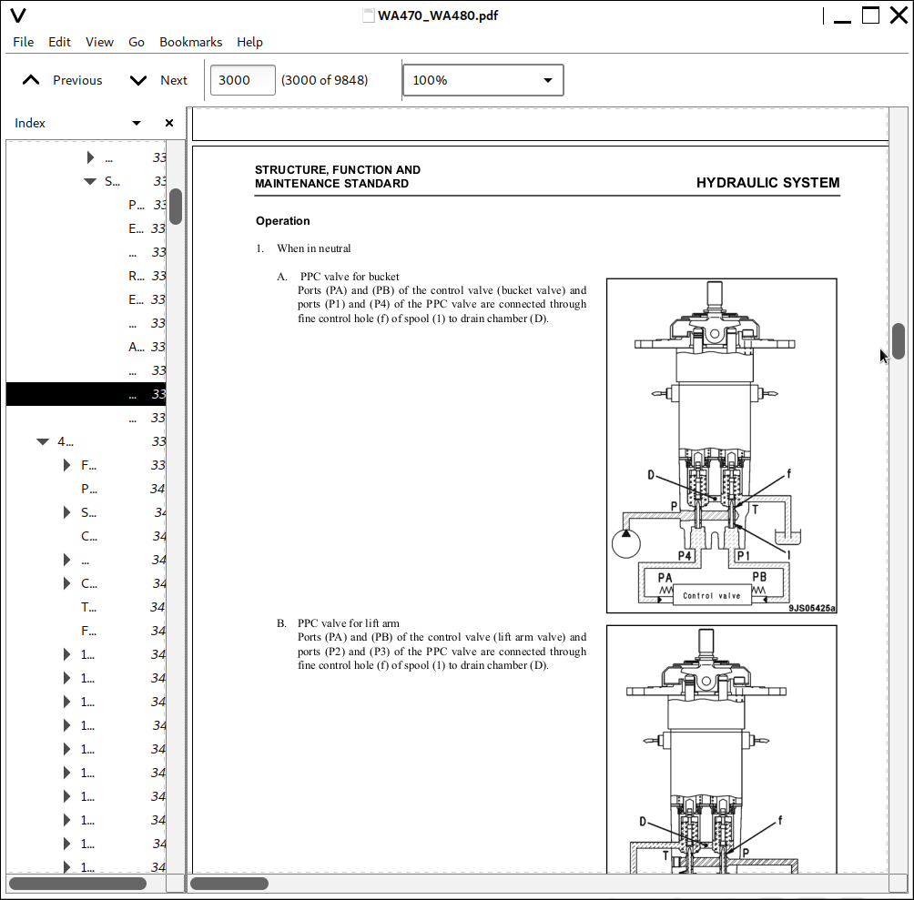
PPC Valve......1140
Work Equipment PPC Valve......1140
Service PPC Valve (If equipped)......1145
Accumulator (for PPC circuit)......1147
Accumulator (for power train circuit)......1148
Accumulator (for ECSS) (If equipped)......1149
Work Equipment PPC Cut-off Solenoid Valve (If equipped)......1150
WORK EQUIPMENT......1153
Work Equipment Linkage......1153
Bucket Positioner And Boom Kick-out......1158
Work Equipment Cylinder......1166
Lift Cylinder......1166
Bucket Cylinder......1166
CAB AND ITS ATTACHMENTS......1168
Cab......1168
Air Conditioner......1169
Air Conditioner Piping Diagram......1169
Refrigerant Circuit Diagram......1171
Air Conditioner Unit......1173
Blower and Intake Unit......1177
Compressor......1179
Condenser......1180
Receiver......1181
Air conditioner panel......1182
ELECTRICAL SYSTEM......1187
Machine Monitor System......1187
System Circuit Diagram......1189
Machine Monitor......1191
Transmission Controller System......1223
Transmission Controller Gear Shifting Control Function......1223
System Circuit Diagram......1259
Transmission Controller......1261
Work Equipment Controller System......1263
System Circuit Diagram......1265
Work Equipment Controller......1267
Electric Transmission Control......1269
Combination Switch......1271
Kickdown Switch and Hold Switch......1273
Load Meter Cancel Switch and Load Meter Subtotal Switch......1273
Multi-function Knob......1274
Joystick Steering Knob......1275
KOMTRAX System......1276
KOMTRAX Terminal......1277
Engine Starting Circuit......1278
Engine Stopping Circuit......1280
Preheating Circuit......1281
Engine Power Mode Selector Circuit......1282
Engine Output Derating Function......1283
Automatic Warm-up Function......1283
Parking Brake Circuit......1284
Sensor......1286
Transmission Input Speed Sensor......1286
Transmission Output Speed Sensor......1286
Cooling Fan Speed Sensor......1286
Torque Converter Oil Temperature Sensor......1287
Hydraulic Oil Temperature Sensor......1287
Transmission Oil Temperature Sensor......1287
Brake Oil Temperature Sensor......1287
Work Equipment Pump Oil Pressure Sensor......1288
Steering Pump Oil Pressure Sensor......1288
Lift Cylinder Head Oil Pressure Sensor (machines equipped with load meter)......1288
Lift Cylinder Bottom Oil Pressure Sensor (machines equipped with load meter)......1288
Transmission Cut-off Oil Pressure Sensor......1289
Coolant Level Sensor......1290
Fuel Level Sensor......1291
Air Cleaner Clogging Sensor (machine equipped with KOMTRAX)......1292
Accelerator Pedal Sensor......1293
Boom Kick-out Proximity Switch......1294
Bucket Positioner Proximity Switch......1294
Lift Arm Potentiometer (machines equipped with load meter)......1295
20 STANDARD VALUE TABLES......1296
STANDARD SERVICE VALUE TABLE......1297
Standard Service Value Table for Engine......1297
Standard Value Table For Chassis......1298
Machine Posture and Procedure for Performance Measurement......1304
30 TESTING AND ADJUSTING......1306
TOOLS......1310
Tools For Testing, Adjusting, And Troubleshooting......1310
ENGINE COMPONENTS......1316
Engine Speed......1316
Exhaust Gas Color......1318
Exhaust Temperature......1320
Valve Clearance......1322
Compression Pressure......1324
Blow-by Pressure......1326
Engine Oil Pressure......1327
EGR Valve Drive Pressure......1328
Intake Air (Boost) Pressure......1330
FUEL SYSTEM......1332
Handling Fuel System Equipment......1332
Releasing Residual Pressure In Fuel System......1332
Fuel Pressure......1333
Fuel Return and Leak Amount......1335
Bleeding Air From Fuel Circuit......1338
Fuel Circuit for Leakage......1340
Reduced Cylinder Mode Operation......1341
No Injection Cranking Operation......1341
Handling of Controller Voltage Circuit......1341
EXHAUST SYSTEM AND PIPING......1342
Check Muffler and Muffler Stack for Looseness and Damage......1342
Check Muffler Function......1342
Check Installed Condition of Cylinder Head and Manifolds......1342
Check Engine Piping for Damage and Looseness......1342
BELTS......1343
Air Conditioner Compressor Belt......1343
Testing......1343
Adjusting......1343
Adjusting Alternator Belt......1344
Testing......1344
Adjusting......1344
TRANSMISSION SPEED SENSOR......1345
DIRECTIONAL LEVER......1346
Adjusting Directional Lever Length......1346
Adjusting Gear Shift Lever Length......1346
FNR AND GEAR SHIFT LEVERS......1347
Testing FNR Lever and Gear Shift Lever......1347
POWER TRAIN OIL PRESSURE......1348
Testing and Adjusting Power Train Oil Pressure......1348
Measurement......1351
Adjustment......1362
FLUSHING TRANSMISSION SYSTEM......1363
Torque Converter and Transmission Hydraulic Circuit......1363
TRANSMISSION VALVE FAILS......1364
Moving Machine When Transmission Valve Is Broken......1364
AXLE DRIVE AND DRIVE SHAFTS......1367
Check of Axle Final Drive for Oil Leakage......1367
Check of Drive Shafts for Looseness, Play and Damage......1367
STEERING SYSTEM......1368
Steering Stop Valve......1368
Testing......1368
Adjusting......1368
Steering Wheel......1370
Steering Oil Pressure......1372
Adjusting......1374
Bleeding Air From Steering Circuit......1375
HYDRAULIC FAN......1376
Hydraulic Drive Fan......1376
Testing......1376
Hydraulic Fan Speed Sensor......1378
Adjustment......1378
Bleeding Air From Hydraulic Drive Fan Circuit......1380
BRAKE SYSTEM......1382
Brake Pedal......1382
Testing......1382
Brake Pedal Linkage......1383
Testing......1383
Adjusting......1383
Brake Performance......1384
Testing......1384
Accumulator Charge Pressure......1385
Testing......1385
Adjusting......1386
Wheel Brake Oil Pressure......1387
Testing......1387
Check Wear of Wheel Brake Disc......1390
Bleed Air From Wheel Brake Circuit......1391
Release Residual Pressure in Brake Accumulator Circuit......1392
Parking Brake Performance......1392
Test......1392
Parking Brake Oil Pressure......1393
Testing......1393
Wear Of Parking Brake Disc......1395
Testing......1395
Manual Release for Parking Brake......1397
WORK EQUIPMENT......1398
Work Equipment Control Lever......1398
Testing......1398
Work Equipment PPC Oil Pressure......1399
Measuring......1399
Adjusting......1402
Work Equipment Oil Pressure......1403
Testing......1403
Adjusting......1407
Bleeding Air From Work Equipment Circuit......1408
Releasing Residual Pressure in Work Equipment Circuit......1409
ACCUMULATOR......1411
Nitrogen Gas Accumulator Pressure of ECSS......1411
Testing......1412
Charging Accumulator......1414
Brake Accumulator Nitrogen Gas Pressure......1418
Testing......1419
Charging Accumulator......1421
BUCKET POSITIONER......1424
Testing......1424
Adjusting......1424
BOOM KICK-OUT......1426
Testing......1426
Adjusting......1426
PROXIMITY SWITCH OPERATION PILOT LAMP......1427
ELECTRICAL SYSTEM......1428
Diode Testing Procedure......1428
Electrical System Troubleshooting......1429
Preparation......1429
KOMTRAX SYSTEM......1434
How to Start KOMTRAX Terminal Operations......1434
Station Opening Check in Machine Side......1435
Application for the Start of Use......1438
Indicator Lamps of KOMTRAX Terminal......1439
MACHINE MONITOR SYSTEM......1442
Adjusting replaced, reassembled or added sensor, controller, etc. with machine monitor......1442
Special functions of machine monitor (EMMS)......1445
Normal functions and special functions of machine monitor......1445
Functions and flow of the service mode......1446
Operator mode......1449
Service Meter/clock Display Function (1)......1449
Load Meter Function (if equipped) (2)......1449
Odometer Display Function (3)......1449
Maintenance Monitoring Function (4)......1449
Telephone Number Input Function (5)......1450
Language Selection Function (6)......1450
Monitor Brightness Adjustment Function (7)......1450
Time Adjustment Function (8)......1451
Travel Speed/Engine Speed Display Selecting Function (9)......1451
Travel Speed/Engine Speed Display/Non-Display Selecting Function (10)......1451
Action Code Display Function (11)......1451
Failure Code Display Function (12)......1452
Service mode......1453
Procedure For Switching To Service Mode And Screen Display (1)......1453
Electrical System Fault History Display Function (ELECTRIC FAULT) (2)......1454
Mechanical System Fault History Display Function (MACHINE FAULT) (3)......1456
Real-Time Monitoring Function (REAL-TIME MONITOR) (4)......1457
Engine Cylinder Cutout Function (CYLINDER CUT- OUT) (5)......1479
No Injection Cranking Function (6)......1480
Adjustment Function (TUNING) (7)......1481
Maintenance Monitoring Function (8)......1498
Operating Information Display Function (9)......1504
OPTIONAL SELECT Function (10)......1506
Machine Serial Number Input Function (11)......1510
Machine Model Select Function (MACHINE) (12)......1510
Initialize Function (13)......1511
PM-CLINIC INSPECTION TABLE......1512
WA470-6 S/N A45001 to A45999......1512
WA480-6 S/N A47001 to A47999......1515
40 TROUBLESHOOTING......1518
FAILURE CODE TABLE......1532
Fuse Locations......1544
Locations and Numbers of Fuse Boxes and Slow Blow Fuse......1546
POINTS TO REMEMBER WHEN TROUBLESHOOTING......1547
SEQUENCE OF EVENTS IN TROUBLESHOOTING......1549
Testing Before Troubleshooting......1550
CLASSIFICATION AND TROUBLESHOOTING PROCEDURES......1551
MODE CHART......1552
Information Contained in Troubleshooting Table......1555
CONNECTION TABLE FOR CONNECTOR PIN NUMBERS......1557
X-Type Connectors......1557
SWP-Type Connectors......1559
M-Type Connectors......1561
S-Type Connectors......1563
MIC-Type Connectors......1565
AMP040-Type Connectors......1567
AMP070-Type Connectors......1569
AMP Connector......1571
L-Type Connector......1571
PA-Type Connector......1572
Bendix (MS) Connector......1572
KES1 (Automobile) Connectors......1573
F-Type Connector......1574
HD30 Series Connectors......1576
DT Series Connectors......1582
DTM Series Connectors......1584
DTHD Series Connectors......1584
DTP Series Connectors......1585
DRC26 Series Connectors......1586
DRC12, 16 Series Connectors......1588
AMP Connectors for Pump Controller (CH700)......1589
BOSCH Connectors for Engine......1590
SUMITOMO Connectors for Engine......1591
CANNON Connector for Engine......1592
AMP Connectors for Engine......1593
FRAMATOME Connectors for Engine......1594
PACKARD Connectors for Engine......1596
DT Series Connectors for Engine......1597
T-BRANCH BOX and T-BRANCH ADAPTER TABLE......1598
FAILURE CODES......1603
1500L0......1604
TORQFLOW Transmission: Double Meshing......1604
15SAL1......1605
ECMV F Clutch: When Command Current is OFF, Fill Signal is ON......1605
15SALH......1607
ECMV F Clutch: When Command Current is ON, Fill Signal is OFF......1607
15SBL1......1609
ECMV R Clutch: When Command Current is OFF, Fill Signal is ON......1609
15SBLH......1611
ECMV R Clutch: When Command Current is ON, Fill Signal is OFF......1611
15SEL1......1613
ECMV 1st Clutch: When Command Current is OFF, Fill Signal is ON......1613
15SELH......1615
ECMV 1st Clutch: When Command Current is ON, Fill Signal is OFF......1615
15SFL1......1617
ECMV 2nd Clutch: When Command Current is OFF, FIll Signal is ON......1617
15SFLH......1619
ECMV 2nd Clutch: When Command Current is ON, Fill Signal is OFF......1619
15SGL1......1621
ECMV 3rd Clutch: When Command Current is OFF, Fill Signal is ON......1621
15GLH......1623
ECMV 3rd Clutch: When Command Current is ON, Fill Signal is OFF......1623
15SHL1......1625
ECMV 4th Clutch: When Command Current is OFF, Fill Signal is ON......1625
15SHLH......1627
ECMV 4th Clutch: When Command Current is ON, Fill Signal is OFF......1627
2F00MA......1629
Parking Brake: Malfunction......1629
2G43ZG......1631
Accumulator: Low Oil Pressure......1631
44K0L4......1633
Bucket Positioner: ON/OFF Signals Disagree......1633
AA1ANX......1637
Air Cleaner: Clogging......1637
AB00L6......1639
Alternator: Signal Disagrees with Operating State of Engine......1639
AB00MA......1641
Alternator: Malfunction......1641
B@BAZG......1643
Engine: Rotation Derating by Low Engine Oil Pressure......1643
B@BAZK......1645
Engine Oil: Low Level......1645
B@BCNS......1647
Coolant: Overheating......1647
B@BCZK......1649
Engine Coolant: Low Level......1649
B@C7NS......1651
Brake Oil: Overheating......1651
b@CENS......1653
Torque Converter Oil: Overheating......1653
B@CENS......1655
Torque Converter Oil: Overheating......1655
B@HANS......1657
Hydraulic Oil: Overheating......1657
CA111......1659
Abnormality in Engine Controller......1659
CA115......1662
Engine Ne or Bkup Speed Sensor Error......1662
CA122......1663
Charge Pressure Sensor High Error......1663
CA123......1665
Charge Pressure Sensor Low Error......1665
CA131......1667
Throttle Sensor High Error......1667
CA132......1669
Throttle Sensor Low Error......1669
CA135......1671
Engine Oil Pressure Sensor High Error......1671
CA141......1673
Engine Oil Pressure Sensor Low Error......1673
CA144......1675
Coolant Sensor High Error......1675
CA145......1677
Coolant Temperature Sensor Low Error......1677
CA153......1679
Charge Temperature Sensor High Error......1679
CA154......1681
Charge Temperature Sensor Low Error......1681
CA187......1683
Sensor Power Supply 2 Low Error......1683
CA221......1685
Atmospheric Pressure Sensor High Error......1685
CA222......1687
Atmospheric Pressure Sensor Low Error......1687
CA227......1688
Sensor Power Supply 2 High Error......1688
CA234......1691
Engine Overspeed......1691
CA238......1693
NE Speed Sensor Power Supply Error......1693
CA263......1695
Fuel Temperature Sensor High Error......1695
CA265......1697
Fuel Temperature Sensor Low Error......1697
CA271......1699
PCV1 Short Circuit......1699
CA272......1701
PCV1 Disconnection......1701
CA273......1703
PCV2 Short Circuit......1703
CA274......1705
PCV2 Disconnection......1705
CA322......1707
Injector #1 Open/Short Error......1707
CA323......1709
Injector #5 Open/Short Error......1709
CA324......1711
Injector #3 Open/Short Error......1711
CA325......1713
Injector #6 Open/Short Error......1713
CA331......1715
Injector #2 Open/Short Error......1715
CA332......1717
Injector #4 Open/Short Error......1717
CA342......1719
Calibration Code Inconsistency......1719
CA351......1721
Injectors Drive Circuit Error......1721
CA352......1723
Sensor Power Supply 1 Low Error......1723
CA386......1725
Sensor Power Supply 1 High Error......1725
CA431......1727
Idle Validation Switch Error......1727
CA432......1729
Idle Validation Action Error......1729
CA441......1731
Battery Voltage Low Error......1731
CA442......1735
Battery Voltage High Error......1735
CA449......1737
Common Rail Pressure High Error 2......1737
CA451......1739
Common Rail Pressure Sensor High Error......1739
CA452......1741
Common Rail Pressure Sensor Low Error......1741
CA553......1742
Common Rail Pressure High Error 1......1742
CA554......1743
Common Rail Pressure Sensor In-Range Error......1743
CA559......1744
Supply Pump Pressure Very Low Error......1744
CA689......1751
Engine Ne Speed Sensor Error......1751
CA731......1753
Engine Bkup Speed Sensor Phase Error......1753
CA757......1754
All Continuous Data Lost Error......1754
CA778......1755
Engine Bkup Speed Sensor Error......1755
CA1228......1757
EGR Valve Servo Error 1......1757
CA1625......1758
EGR Valve Servo Error 2......1758
CA1633......1759
KOMNET Datalink Timeout Error......1759
CA2185......1761
Throttle Sensor Supply Voltage High Error......1761
CA2186......1763
Throttle Sensor Power Supply Low Error......1763
CA2249......1765
Supply Pump Pressure Very Low Error 2......1765
CA2271......1766
EGR Valve Lift Sensor High Error......1766
CA2272......1768
EGR Valve Lift Sensor Low Error......1768
CA2351......1769
EGR Valve Solenoid Operation Short Circuit......1769
CA2352......1771
EGR Valve Solenoid Operation Disconnect......1771
CA2555......1773
Intake Heater Relay Disconnection Error......1773
CA2556......1775
Intake Heater Relay Short Circuit Error......1775
D150KA......1777
Emergency Steering Relay: Disconnection......1777
D150KB......1779
Emergency Steering Relay: Short Circuit......1779
D150KY......1781
Emergency Steering Relay: Short Circuit With Power Supply Line......1781
D160KA......1783
Backup Lamp Relay Output: Disconnection......1783
D160KB......1785
Backup Lamp Relay Output: Short Circuit......1785
D191KA......1787
Joystick Steering Neutral Safety Relay: Disconnection......1787
D191KB......1789
Joystick Steering Neutral Safety Relay: Short Circuit......1789
D191KY......1791
Joystick Steering Neutral Safety Relay: Short Circuit With Power Supply Line......1791
D192KA......1793
ECSS Solenoid: Disconnection......1793
D192KB......1795
ECSS Solenoid: Short Circuit......1795
D192KY......1797
ECSS Solenoid: Short Circuit With Power Supply Line......1797
D193KA......1799
Joystick Steering Solenoid Cut-Off Relay: Disconnection......1799
D193KB......1801
Joystick steering solenoid cut-off relay: Short circuit......1801
D193KY......1803
Joystick Steering Solenoid Cut-Off Relay: Short Circuit With Power Supply Line......1803
D5ZHKA......1805
Terminal C Signal: Disconnection......1805
D5ZHKB......1809
Terminal C Signal: Short Circuit......1809
D5ZHKZ......1813
Terminal C Signal: Disconnection Or Short Circuit......1813
D5ZHL6......1817
Terminal C Signal: Signal Does Not Match Engine Running Or Stopped State......1817
DA80L4......1821
Auto Grease Controller: ON/OFF Signals Disagree......1821
DAF3KK......1823
Machine Monitor: Low Source Voltage (Input)......1823
DAF5KP......1825
Machine Monitor: Low Output Voltage......1825
DAFRKR......1829
CAN Communication With Machine Monitor: Defective Communication (Abnormality In Target Component System)......1829
DAQ0KK......1831
Transmission Controller: Low Source Voltage......1831
DAQ0KT......1833
Transmission Controller: Abnormality In Controller......1833
DAQ1KA......1834
Terminal ACC Input: Disconnection......1834
DAQ2KK......1837
Transmission Controller Load Power Supply Line: Low Source Voltage (Input)......1837
DAQ9KQ......1839
Transmission Controller Model Selection: Disagreement of Model Selection Signals......1839
DAQRKR......1840
CAN Communication with Transmission Controller: Defective Communication (Abnormality in Target Component System)......1840
DAQRMA......1842
Transmission Controller Option Setting: Malfunction......1842
DB2RKR......1843
CAN Communication with Engine Controller: Defective Communication (Abnormality in Target Component System)......1843
DB90KK......1845
Work Equipment Controller: Low Source Voltage (Input)......1845
DB90KT......1847
Work Equipment Controller: Abnormality in Controller......1847
DB92KK......1849
Work Equipment Controller Load Power Supply Line: Low Source Voltage (Input)......1849
DB95KX......1851
Work Equipment Controller Power Supply Output: Out of Input Signal Range......1851
DB99KQ......1853
Work Equipment Controller Model Selection: Disagreement in Model Selection Signals......1853
DB9RKR......1854
CAN Communication With Work Equipment Controller: Defective Communication (Abnormality in Target Component System)......1854
DB9RMA......1856
Work equipment controller option setting: Malfunction......1856
DB9RMC......1857
CAN Communication With Transmission Controller, Engine Controller and Machine Monitor: Defective Operation......1857
DD15LD......1861
n Switch (Panel Switch 1): Switch Is Kept Pressed For Long Time......1861
DD16LD......1863
Switch (Panel Switch 2): Switch is Kept Pressed for Long Time......1863
DD17LD......1865
< Switch (Panel Switch 3): Switch Is Kept Pressed For Long Time......1865
DD18LD......1867
> Switch (Panel Switch 4): Switch Is Kept Pressed For Long Time......1867
DD1ALD......1869
Remote Positioner Raise/lower Set Switch (Raise): Switch Is Kept Pressed For Long Time......1869
DD1BLD......1871
Remote Positioner Raise/lower Set Switch (Lower): Switch Is Kept Pressed For Long Time......1871
DD1CLD......1873
Load Meter Subtotal Switch: Switch Is Kept Pressed For Long Time......1873
DD1FLD......1875
Load Meter Mode Selector Switch (A/B): Switch Is Kept Pressed For Long Time......1875
DD1GLD......1877
Load Meter Mode Selector Switch (+/-): Switch Is Kept Pressed For Long Time......1877
DD1HLD......1879
Load Meter Display Selector Switch: Switch Is Kept Pressed For Long Time......1879
DD1NLD......1881
Fan Reverse Switch: Switch Is Kept Pressed For Long Time......1881
DD1NL4......1883
Fan Automatic Reverse Switch: Switch Is Kept Pressed For Long Time......1883
DDB6L4......1885
Parking Brake Switch (Neutralizer): ON/OFF Signals Disagree......1885
DDD1LD......1889
Remote Positioner Bucket Angle Set Switch: Switch Is Kept Pressed For Long Time......1889
DDE5MA......1891
Emergency Steering Drive Switch: Malfunction......1891
DDK3KA......1893
Right FNR Switch: Disconnection......1893
DDK4KA......1896
Joystick Steering FNR Switch: Disconnection......1896
DDK5L4......1899
Joystick Steering Shift-Up/Down Switch: ON/OFF Signals Disagree......1899
DDK6KA......1901
FNR Lever Switch: Disconnection......1901
DDK6KB......1905
FNR Lever Switch: Short Circuit......1905
DDS5KA......1907
Steering Pressure Switch Signal: Disconnected......1907
DDS5KB......1909
Steering pressure Switch Signal: Short Circuit......1909
DDS5L6......1911
Steering: Low Oil Pressure......1911
DDT0L4......1913
Shift Mode Selector Switch: ON/OFF Signals Disagree......1913
DDT4LD......1915
Transmission Cut-Off Set Switch: Switch Is Kept Pressed For Long Time......1915
DDW9LD......1917
Kick-Down Switch: Switch Is Kept Pressed For Long Time......1917
DDWLLD......1919
Hold Switch: Switch Is Kept Pressed For Long Time......1919
DDY0LD......1921
Load Meter Cancel Switch: Switch Is Kept Pressed For Long Time......1921
DF10KA......1923
Transmission Shift Lever Switch: Disconnected......1923
DF10KB......1927
Transmission Shift Lever Switch: Short Circuit......1927
DGF1KA......1929
Transmission Oil Temperature Sensor: Disconnected......1929
DGF1KB......1931
Transmission Oil Temperature Sensor: Short Circuit......1931
DGH2KX......1933
Hydraulic Oil Temperature Sensor: Out Of Input Signal Range......1933
DGR2KA......1935
Rear Brake Oil Temperature Sensor: Disconnected......1935
DGR2KX......1937
Rear Brake Oil Temperature Sensor: Out Of Input Signal Range......1937
DGT1KX......1939
Torque converter oil temperature sensor: Out of input signal range......1939
DH21KA......1941
Loader Pump Pressure Sensor: Disconnection......1941
DH21KB......1943
Loader Pump Pressure Sensor: Power Supply Line Short......1943
DHPCKX......1945
Lift Arm Cylinder Bottom Pressure Sensor: Out Of Input Signal Range......1945
DHPDKX......1947
Lift Arm Cylinder Head Pressure Sensor: Out Of Input Signal Range......1947
DHT1KX......1949
Transmission Cut-Off Pressure Sensor: Out Of Input Signal Range......1949
DHT8KA......1951
Steering Pump Pressure Sensor: Disconnection......1951
DHT8KB......1953
Steering Pump Pressure Sensor: Short Circuit......1953
DK59KA......1955
Lift Arm EPC Lever Potentiometer (Main): Disconnection......1955
DK59KY......1958
Lift Arm EPC Lever Potentiometer (Main): Short Circuit With Power Supply Line......1958
DK59L8......1961
Lift Arm EPC Lever Potentiometer (Main): Analog Signals Disagree......1961
DK5AKA......1964
Lift Arm EPC Lever Potentiometer (Sub): Disconnection......1964
DK5AKY......1967
Lift Arm EPC Lever Potentiometer (Sub): Short Circuit With Power Supply Line......1967
DK5BKA......1970
Bucket EPC Lever Potentiometer (Main): Disconnection......1970
DK5BKY......1973
Bucket EPC Lever Potentiometer (Main): Short Circuit With Power Supply Line......1973
DK5BL8......1976
Bucket EPC Lever Potentiometer (Main): Analog Signals Disagree......1976
DK5CKA......1979
Bucket EPC Lever Potentiometer (Sub): Disconnection......1979
DK5CKY......1982
Bucket EPC Lever Potentiometer (Sub): Short Circuit With Power Supply Line......1982
DK5FKA......1985
Joystick Steering EPC Lever Potentiometer (Main): Disconnection......1985
DK5FKY......1989
Joystick steering EPC lever potentiometer (Main): Short circuit with power supply line......1989
DK5GKA......1991
Joystick Steering EPC Lever Potentiometer (Sub): Disconnection......1991
DK5GKY......1994
Joystick Steering EPC Lever Potentiometer (Sub): Short Circuit With Power Supply Line......1994
DK5FL8......1996
Joystick Steering EPC Lever Potentiometer (Main): Analog Signals Disagree......1996
DKA0KA......1999
Lift Arm Angle Sensor: Disconnection......1999
DKA0KY......2001
Lift Arm Angle Sensor: Short Circuit With Power Supply Line......2001
DKA0L0......2003
Lift Arm Angle Sensor: Double Meshing......2003
DLF1KA......2005
Transmission Input Speed Sensor: Disconnection......2005
DLF1LC......2007
Transmission Input Speed Sensor: Short Circuit......2007
DLM3KA......2009
Fan Speed Sensor: Disconnection......2009
DLM3LC......2011
Fan Speed Sensor: Short Circuit......2011
DLT3KA......2013
Transmission Output Speed Sensor: Disconnection......2013
DLT3LC......2015
Transmission Output Speed Sensor: Out Of Input Signal Range......2015
DT20KB......2017
Transmission Cut-Off Indicator Lamp: Short Circuit......2017
DUM1KB......2019
Remote Positioner Raise Set Indicator Lamp: Short Circuit......2019
DUM2KB......2021
Remote Positioner Lower Set Indicator Lamp: Short Circuit......2021
DV00KB......2023
Alarm Buzzer: Short Circuit......2023
DW4PKA......2025
Lift Arm Raise EPC Solenoid: Disconnection......2025
DW4PKB......2027
Lift Arm Raise EPC Solenoid: Short Circuit......2027
DW4PKY......2029
Lift Arm Raise EPC Solenoid: Short Circuit With Power Supply Line......2029
DW4QKA......2031
Lift Arm Lower EPC Solenoid: Disconnection......2031
DW4QKB......2033
Lift Arm Lower EPC Solenoid: Short Circuit......2033
DW4QKY......2035
Lift Arm Lower EPC Solenoid: Short Circuit With Power Supply Line......2035
DW4RKA......2037
Bucket Tilt EPC Solenoid: Disconnection......2037
DW4RKB......2039
Bucket Tilt EPC Solenoid: Short Circuit......2039
DW4RKY......2041
Bucket Tilt EPC Solenoid: Short Circuit With Power Supply Line......2041
DW4SKA......2043
Bucket Dump EPC Solenoid: Disconnection......2043
DW4SKB......2045
Bucket Dump EPC Solenoid: Short Circuit......2045
DW4SKY......2047
Bucket Dump EPC Solenoid: Short Circuit With Power Supply Line......2047
DW7BKA......2049
Fan Reverse Solenoid: Disconnection......2049
DW7BKB......2051
Fan Reverse Solenoid: Short Circuit......2051
DW7BKY......2053
Fan Reverse Solenoid: Short Circuit With Power Supply Line......2053
DWM1KA......2055
Work Equipment Neutral Lock Solenoid: Disconnection......2055
DWM1KB......2057
Work Equipment Neutral Lock Solenoid: Short Circuit......2057
DWM1KY......2059
Work Equipment Neutral Lock Solenoid: Short Circuit With Power Supply Line......2059
DWN6KA......2061
Lift Arm Raise Magnet Detent Solenoid: Disconnection......2061
DWN6KB......2063
Lift Arm Raise Magnet Detent Solenoid: Short Circuit......2063
DWN6KY......2065
Lift Arm Raise Magnet Detent Solenoid: Short Circuit With Power Supply Line......2065
DWN7KA......2067
Lift Arm Float Magnet Detent Solenoid: Disconnection......2067
DWN7KB......2069
Lift Arm Float Magnet Detent Solenoid: Short Circuit......2069
DWN7KY......2071
Lift Arm Float Magnet Detent Solenoid: Short Circuit With Power Supply Line......2071
DWN8KA......2073
Bucket Tilt Magnet Detent Solenoid: Disconnection......2073
DWN8KB......2075
Bucket Tilt Magnet Detent Solenoid: Short Circuit......2075
DWN8KY......2077
Bucket Tilt Magnet Detent Solenoid: Shorted With The Power Source......2077
DX16KA......2079
Fan Pump EPC Solenoid: Disconnection......2079
DX16KB......2081
Fan Pump EPC Solenoid: Short Circuit......2081
DX16KY......2083
Fan Pump EPC Solenoid: Short Circuit With Power Supply Line......2083
DXA1KA......2085
Loader Pump PC-EPC Solenoid: Disconnection......2085
DXA1KB......2087
Loader Pump PC-EPC Solenoid: Short Circuit......2087
DXANKA......2089
Steering Pump PC-EPC Solenoid: Disconnection......2089
DXANKB......2091
Steering Pump PC-EPC Solenoid: Short Circuit......2091
DXH1KA......2093
Lockup ECMV Solenoid: Disconnection......2093
DXH1KB......2095
Lockup ECMV Solenoid: Short Circuit......2095
DXH1KY......2097
Lockup ECMV Solenoid: Short Circuit With Power Supply Line......2097
DXH4KA......2099
1st Clutch ECMV Solenoid: Disconnection......2099
DXH4KB......2101
1st Clutch ECMV Solenoid: Short Circuit......2101
DXH4KY......2103
1st Clutch ECMV Solenoid: Short Circuit With Power Supply Line......2103
DXH5KA......2105
2nd Clutch ECMV Solenoid: Disconnection......2105
DXH5KB......2107
2nd Clutch ECMV Solenoid: Short Circuit......2107
DXH5KY......2109
2nd Clutch ECMV Solenoid: Short Circuit With Power Supply Line......2109
DXH6KA......2111
3rd Clutch ECMV Solenoid: Disconnection......2111
DXH6KB......2113
3rd cluTch ECMV Solenoid: Short Circuit......2113
DXH6KY......2115
3rd Clutch ECMV Solenoid: Short Circuit With Power Supply Line......2115
DXH7KA......2117
R Clutch ECMV Solenoid: Disconnection......2117
DXH7KB......2119
R Clutch ECMV Solenoid: Short Circuit......2119
DXH7KY......2121
R Clutch ECMV Solenoid: Short Circuit With Power Supply Line......2121
DXH8KA......2123
F Clutch ECMV Solenoid: Disconnection......2123
DXH8KB......2125
F Clutch ECMV Solenoid: Short Circuit......2125
DXH8KY......2127
F Clutch ECMV Solenoid: Short Circuit With Power Supply Line......2127
DXHHKA......2129
4th Clutch ECMV Solenoid: Disconnection......2129
DXHHKB......2131
4th Clutch ECMV Solenoid: Short Circuit......2131
DXHHKY......2133
4th Clutch ECMV Solenoid: Short Circuit With Power Supply Line......2133
DXHLKA......2135
Joystick Steering Right EPC Solenoid: Disconnection......2135
DXHLKB......2137
Joystick Steering Right EPC Solenoid: Short Circuit......2137
DXHLKY......2139
Joystick steering right EPC solenoid: Short circuit with power supply line......2139
DXHMKA......2141
Joystick Steering Left EPC Solenoid: Disconnection......2141
DXHMKB......2143
Joystick Steering Left EPC Solenoid: Short Circuit......2143
DXHMKY......2145
Joystick Steering Left EPC Solenoid: Short Circuit With Power Supply Line......2145
DY30MA......2147
Motor-Driven Emergency Steering Pump Failure (During Operation Of Machine)......2147
DY30MC......2150
Motor-Driven Emergency Steering Pump Failure (Malfunction In Manual Mode)......2150
DY30ME......2153
Emergency Steering: Operating For More Than 1 Minute......2153
E-1......2156
Engine Does Not Start......2156
E-2......2163
Wiper does not operate......2163
E-3......2167
Windshield Washer Does Not Operate......2167
E-4......2170
Headlamp, Clearance Lamp, Tail Lamp, And License Lamp Do Not Light Up Or Go Off......2170
E-5......2178
Working Lamp Does Not Light Up Or Go Off......2178
E-6......2183
Turn Signal Lamp And Hazard Lamp Do Not Light Up Or Go Off......2183
E-7......2189
Brake Lamp Does Not Light Or It Keeps Lighting Up......2189
E-8......2191
Backup Lamp Does Not Light Or It Keeps Lighting Up......2191
E-9......2193
Backup Buzzer Does Not Sound Or It Keeps Sounding......2193
E-10......2195
Horn Does Not Sound Or It Keeps Sounding......2195
E-11......2197
Alarm Buzzer Does Not Sound Or It Keeps Sounding......2197
E-12......2199
Air Conditioner Does Not Operate Or Stop......2199
E-13......2203
The KOMTRAX System Does Not Work Properly......2203
E-14......2205
When Kick-down Switch Is Turned ON, Kick-down Operation Does Not Start......2205
E-15......2207
When Hold Switch Is Pressed, Holding Operation Does Not Start......2207
E-16......2209
Transmission Is Kept In Neutral, Or Brake Drags When Directional Lever Is Operated While Parking Brake Is Applied......2209
E-17......2211
Transmission Cut-off Mode Cannot Be Set Or Reset......2211
E-18......2213
Transmission Cut-off Set Cannot Be Reset......2213
E-19......2215
FNR Switch Mode Cannot Be Set Or Reset......2215
E-20......2217
Fan Reverse Function Cannot Be Used Or Reset......2217
E-21......2219
Discharge From Loader Pump Does Not Rise From Minimum Level......2219
E-22......2221
ECSS Function Cannot Be Used Or Reset......2221
E-23......2223
When Parking Brake Is Turned ON, Parking Brake Indicator Lamp Does Not Light Up......2223
E-24......2227
When Emergency Brake Operates, Brake Oil Pressure Caution Lamp Does Not Operate......2227
E-25......2229
Air Cleaner Clogging Indicator Lamp Does Not Light Up......2229
E-26......2231
Radiator Coolant Level Caution Lamp Does Not Light Up......2231
E-27......2232
Hydraulic Oil Temperature Gauge Does Not Rise And Hydraulic Oil Temperature Caution Lamp Does Not Light Up......2232
E-28......2233
Torque Converter Oil Temperature Gauge Does Not Rise And Torque Converter Oil Temperature Caution Lamp Does Not Light Up......2233
E-29......2235
Steering Oil Pressure Caution Lamp Does Not Light Up......2235
E-30......2237
Abnormality In n Switch (Panel Switch 1) Input......2237
E-31......2239
Abnormality In Switch (Panel Switch 1) Input......2239
E-32......2241
Abnormality In < Switch (Panel Switch 2) Input......2241
E-33......2243
Abnormality In > Switch (Panel Switch 2) Input......2243
H-MODE HYDRAULIC AND MECHANICAL SYSTEM......2245
Method Of Using Troubleshooting Chart......2245
Table Of Failure And Causes......2247
H-1......2251
The Machine Does Not Start......2251
H-2......2253
Torque Converter Lockup Is Not Switched Off (Engine Stalls) [Machine With Lockup Clutch (If Equipped)]......2253
H-3......2254
Torque Converter Lockup Is Not Switched On [Machine With Lockup Clutch (If Equipped)]......2254
H-4......2255
The Travel Speed Is Slow, The Thrusting Force Is Weak, The Uphill Traveling Power Is Weak, And The Gear Is Not Shifted......2255
H-5......2257
Shocks Are Large At The Times Of Starting And Shifting Gear......2257
H-6......2259
Time Lag Is Large At The Times Of Starting And Shifting Gear......2259
H-7......2261
The Torque Converter Oil Temperature Is High......2261
H-8......2262
Steering Does Not Turn......2262
H-9......2263
Steering Does Not Turn [Machine With Joystick Steering (If Equipped)]......2263
H-10......2264
Steering Response Is Poor......2264
H-11......2265
Turning, Response Of Steering Is Poor [Machine With Joystick Steering (If Equipped)]......2265
H-12......2266
Steering Is Stiff......2266
H-13......2267
When Machine Turns, It Shakes Or Makes Large Shocks......2267
H-14......2268
When Machine Turns, It Shakes Or Makes Large Shocks [Machine With Joystick Steering (If Equipped)]......2268
H-15......2269
The Wheel Brake Does Not Work Or Does Not Work Well......2269
H-16......2270
The Wheel Brake Is Not Released Or It Drags......2270
H-17......2271
The Parking Brake Does Not Work Or Does Not Work Well......2271
H-18......2272
The Parking Brake Is Not Released Or It Drags (Including Emergency Release System)......2272
H-19......2273
Lift Arm Does Not Rise......2273
H-20......2274
LIft Arm Speed Is Low Or Rising Force Of Lift Arm Is Insufficient......2274
H-21......2275
When Rising, The Lift Arm Comes To Move Slowly At Specific Height......2275
H-22......2275
The Lift Arm Cylinder Cannot Hold Down The Bucket (Bucket Floats)......2275
H-23......2275
Hydraulic Drift Of The Lift Arm Is Large......2275
H-24......2275
The Lift Arm Wobbles During Operation......2275
H-25......2276
Bucket Does Not Tilt Back......2276
H-26......2277
Bucket Speed Is Low Or Tilting Back Force Is Insufficient......2277
H-27......2278
The Bucket Comes To Operate Slowly In The Midst Of Tilting-back......2278
H-28......2278
The Bucket Cylinder Cannot Hold Down The Bucket......2278
H-29......2278
Hydraulic Drift Of The Bucket Is Large......2278
H-30......2278
The Bucket Wobbles During Travel With Cargo (The Work Equipment Valve Is Set To Hold)......2278
H-31......2279
Lift Arm And Bucket Control Levers Do Not Move Smoothly And Are Heavy......2279
H-32......2280
During Operation Of The Machine, Engine Speed Lowers Remarkably Or Engine Stalls......2280
H-33......2280
Large Shock Is Made When Work Equipment Starts And Stops......2280
H-34......2280
When Work Equipment Circuit Is Relieved Singly, Other Work Equipment Moves......2280
H-35......2281
ECSS Does Not Operate, And Pitching, Bouncing Occur......2281
50 DISASSEMBLY AND ASSEMBLY......2282
HOW TO READ THIS MANUAL......2286
Removal And Installation Of Assemblies......2286
Special Tools......2286
Removal......2286
Installation......2286
Disassembly And Assembly Of Assemblies......2287
Special Tools......2287
Disassembly......2287
Assembly......2288
SPECIAL TOOLS LIST......2289
Sketches of special tools......2294
CONNECTOR REPAIR PROCEDURES......2315
Stripping Insulation......2315
Wire Inspection......2315
Contact Terminal Removal (HD30 Type)......2316
Crimping Contact Terminal (HD30 Type)......2317
Insertion Of Contact Terminal (HD30 Type)......2318
Contact Terminal Removal (DT Type)......2319
Crimping Contact Terminal (DT Type)......2320
Insertion Of Contact Terminal (DT Type)......2321
ENGINE AND COOLING SYSTEM......2322
Engine......2322
Removal......2322
Installation......2326
Engine Hood......2327
Removal......2327
Installation......2329
Radiator......2330
Removal......2330
Installation......2333
Aftercooler......2334
Removal......2334
Installation......2336
Oil Cooler......2337
Removal......2337
Installation......2338
Cooling Fan And Drive Motor......2339
Removal......2339
Installation......2343
Fuel Supply Pump......2344
Removal......2344
Installation......2348
Fuel Injector......2353
Removal......2353
Installation......2356
Cylinder Head......2361
Removal......2361
Installation......2367
Engine Front Oil Seal......2370
Removal......2370
Installation......2371
Engine Rear Oil Seal......2372
Removal......2372
Installation......2373
Fuel Tank......2377
Removal......2377
Installation......2380
POWER TRAIN......2381
Torque Converter And Transmission......2381
Removal......2381
Installation......2387
Disassembly......2388
Assembly......2407
Torque Converter (Standard Specification)......2432
Disassembly......2432
Assembly......2435
Torque Converter (Lockup Specification)......2438
Disassembly......2438
Assembly......2442
Clutch Pack......2448
Disassembly......2448
Assembly......2465
Front Axle......2484
Removal......2484
Installation......2486
Rear Axle......2487
Removal......2487
Installation......2493
Axle Housing......2495
Disassembly......2495
Assembly......2500
Differential......2507
Disassembly......2508
Assembly......2516
BRAKE SYSTEM......2531
Parking Brake Disc And Plate......2531
Removal......2531
Installation......2534
UNDERCARRIAGE AND FRAME......2535
Center Hinge Pin......2535
Removal......2535
Installation......2540
Counterweight......2545
Removal......2545
Installation......2547
HYDRAULIC SYSTEM......2548
Steering Demand Valve......2548
Removal......2548
Installation......2551
Work Equipment Valve......2552
Removal......2552
Installation......2555
Brake Charge Valve......2556
Removal......2556
Installation......2556
Hydraulic Tank......2557
Removal......2557
Installation......2559
Steering And Power Train Pump......2560
Removal......2560
Installation......2560
Work Equipment And Cooling Fan Pump......2561
Removal......2561
Installation......2562
Hydraulic Cylinder......2563
Disassembly......2564
Assembly......2567
WORK EQUIPMENT......2573
Removal......2573
Installation......2576
CAB AND ITS ATTACHMENTS......2578
Operator's Cab And Floor Frame......2578
Removal......2578
Installation......2582
Operator's Cab Glass (Stuck Glass)......2583
Removal......2583
Installation......2585
Operator's Seat......2593
Disassembly......2593
Assembly......2600
Manufactured By GRAMMER (Seat)......2605
Upper seat......2605
Suspension......2613
Air Conditioner Unit......2645
Removal......2645
Engine Controller......2651
Removal......2651
Installation......2651
Transmission Controller......2652
Removal......2652
Installation......2652
KOMTRAX Terminal......2653
Removal......2653
Installation......2653
90 DIAGRAMS AND DRAWINGS......2654
100 HYDRAULIC DIAGRAMS AND DRAWINGS......2654
POWER TRAIN HYDRAULIC CIRCUIT DIAGRAM - WITHOUT LOOKUP CLUTCH......2655
POWER TRAIN HYDRAULIC DIAGRAM - WITH LOOKUP CLUTCH......2656
AUTOMATIC GREASING CIRCUIT DIAGRAM......2657
AUTOMATIC GREASING CITCUIT DIAGRAM ASSEMBLY / PARTS......2658
HYDRAULIC CIRCUIT DIAGRAM......2660
200 ELECTRICAL DIAGRAMS AND DRAWINGS......2664
ELECTRICAL CIRCUIT DIAGRAM (1/10)......2666
ELECTRICAL CIRCUIT DIAGRAM (2/10)......2668
ELECTRICAL CIRCUIT DIAGRAM (3/10)......2670
ELECTRICAL CIRCUIT DIAGRAM (4/10)......2672
ELECTRICAL CIRCUIT DIAGRAM 5/10)......2674
ELECTRICAL CIRCUIT DIAGRAM (6/10)......2676
ELECTRICAL CIRCUIT DIAGRAM (7/10)......2678
ELECTRICAL CIRCUIT DIAGRAM (8/10)......2680
ELECTRICAL CIRCUIT DIAGRAM (9/10)......2682
ELECTRICAL CIRCUIT DIAGRAM (10/10)......2684
WORK EQUIPMENT CONTROLLER SYSTEM ELECTRICAL CIRCUIT DIAGRAM......2686
CONECTOR LIST AND STEREOGRAM......2688
CEBM023002 - Wheel Loader WA470-6, WA480-6 Shop Manual......2700
CEBM023002 - WA470-6, WA480-6......2700
CONTENTS......2701
REVISED PAGES......2702
SAFETY......2718
SAFETY NOTICE......2718
IMPORTANT SAFETY NOTICE......2718
GENERAL PRECAUTIONS......2718
PREPARATIONS FOR WORK......2718
PRECAUTIONS DURING WORK......2718
GENERAL......2720
HOW TO READ THE SHOP MANUAL......2721
VOLUMES......2721
DISTRIBUTION AND UPDATING......2721
FILING METHOD......2721
REVISED EDITION MARK......2721
REVISIONS......2721
SYMBOLS......2721
HOISTING INSTRUCTIONS......2722
HOISTING......2722
WIRE ROPES......2722
MAINTENANCE STANDARD TERMINOLOGY......2723
HANDLING ELECTRIC EQUIPMENT AND HYDRAULIC COMPONENTS......2725
Handling Connectors Used for Engines......2734
Slide Lock Type......2734
Pull Lock Type......2734
Push Lock Type......2735
Turn-housing Type (Round Green Connector)......2737
PRECAUTIONS FOR OPERATIONS......2738
Precautions when Carrying Out Removal Work......2738
Precautions when Carrying Out Installation Work......2739
Precautions when Completing the Operation......2740
PUSH PULL COUPLER......2741
TYPE 1......2741
DISCONNECTION......2741
CONNECTION......2741
TYPE 2......2742
DISCONNECTION......2742
CONNECTION......2742
TYPE 3......2743
DISCONNECTION......2743
CONNECTION......2743
COATING MATERIALS......2744
STANDARD TIGHTENING TORQUE......2746
STANDARD TIGHTENING TORQUE OF BOLTS AND NUTS......2746
TIGHTENING TORQUE OF HOSE NUTS......2747
TIGHTENING TORQUE OF SPLIT FLANGE BOLTS......2747
TIGHTENING TORQUE FOR FLARED NUTS......2747
TABLE OF TIGHTENING TORQUES FOR O-RING BOSS PIPING JOINTS......2748
TABLE OF TIGHTENING TORQUES FOR O-RING BOSS PLUGS......2748
TIGHTENING TORQUE TABLE FOR HOSES (TAPER SEAL TYPE AND FACE SEAL TYPE)......2748
ELECTRIC WIRE CODE......2749
CLASSIFICATION BY THICKNESS......2749
CLASSIFICATION BY COLOR AND CODE......2749
CONVERSION TABLES......2750
METHOD OF USING THE CONVERSION TABLE......2750
LIST OF ABBREVIATIONS......2756
List of Abbreviations Used in the Shop Manual......2756
List of Abbreviations Used in the Circuit Diagrams......2760
01 GENERAL......2762
SPECIFICATIONS......2763
Dimension Drawing......2763
Specification Tables......2765
WEIGHT TABLE......2769
TABLE OF FUEL, COOLANT AND LUBRICANTS......2771
10 STRUCTURE, FUNCTION AND MAINTENANCE STANDARD......2774
ENGINE AND COOLING SYSTEM......2779
Engine and Transmission Mounting......2779
Cooling System......2781
Cooling Fan Pump......2783
Operation......2787
Servo Valve......2788
Cooling Fan Motor......2791
Hydraulic Motor......2793
Suction Valve......2794
Operation of Reversible Valve......2795
Safety Valve......2796
20 STANDARD VALUE TABLES ......3154
STANDARD SERVICE VALUE TABLE......3155
Standard Service Value Table for Engine......3155
Standard Value Table For Chassis......3156
Machine Posture and Procedure for Performance Measurement......3163
30 TESTING AND ADJUSTING......3166
TOOLS......3170
Tools For Testing, Adjusting, And Troubleshooting......3170
ENGINE COMPONENTS......3176
Engine Speed......3176
Exhaust Gas Color......3179
Exhaust Temperature......3181
Valve Clearance......3184
Compression Pressure......3186
Blow-by Pressure......3188
Engine Oil Pressure......3189
EGR Valve Drive Pressure......3190
Intake Air (Boost) Pressure......3192
FUEL SYSTEM......3194
Handling Fuel System Equipment......3194
Releasing Residual Pressure In Fuel System......3194
Fuel Pressure......3195
Fuel Return and Leak Amount......3197
Bleeding Air From Fuel Circuit......3200
Fuel Circuit for Leakage......3202
Reduced Cylinder Mode Operation......3203
No Injection Cranking Operation......3203
Handling of Controller Voltage Circuit......3203
EXHAUST SYSTEM AND PIPING......3204
Check Muffler and Muffler Stack for Looseness and Damage......3204
Check Muffler Function......3204
Check Installed Condition of Cylinder Head and Manifolds......3204
Check Engine Piping for Damage and Looseness......3204
BELTS......3205
Air Conditioner Compressor Belt......3205
Testing......3205
Adjusting......3205
Adjusting Alternator Belt......3206
Testing......3206
Adjusting......3206
TRANSMISSION SPEED SENSOR......3207
DIRECTIONAL LEVER......3208
Adjusting Directional Lever Length......3208
Adjusting Gear Shift Lever Length......3208
FNR AND GEAR SHIFT LEVERS......3209
Testing FNR Lever and Gear Shift Lever......3209
POWER TRAIN OIL PRESSURE......3210
Testing and Adjusting Power Train Oil Pressure......3210
Measurement......3213
Adjustment......3224
FLUSHING TRANSMISSION SYSTEM......3225
Torque Converter and Transmission Hydraulic Circuit......3225
TRANSMISSION VALVE FAILS......3227
Moving Machine When Transmission Valve Is Broken......3227
AXLE DRIVE AND DRIVE SHAFTS......3230
Check Axle Final Drive for Oil Leakage......3230
Check Drive Shafts for Looseness, Play and Damage......3230
STEERING SYSTEM......3231
Steering Stop Valve......3231
Testing......3231
Adjusting......3231
Steering Wheel......3233
Steering Oil Pressure......3235
Adjusting......3237
Bleeding Air From Steering Circuit......3238
HYDRAULIC FAN......3239
Hydraulic Drive Fan......3239
Testing......3239
Hydraulic Fan Speed Sensor......3241
Adjustment......3241
Bleeding Air From Hydraulic Drive Fan Circuit......3243
BRAKE SYSTEM......3245
Brake Pedal......3245
Testing......3245
Brake Pedal Linkage......3246
Testing......3246
Adjusting......3246
Brake Performance......3247
Testing......3247
Accumulator Charge Pressure......3248
Testing......3248
Adjusting......3249
Wheel Brake Oil Pressure......3250
Testing......3250
Check Wear of Wheel Brake Disc......3253
Bleed Air From Wheel Brake Circuit......3254
Release Residual Pressure in Brake Accumulator Circuit......3255
Parking Brake Performance......3255
Test......3255
Parking Brake Oil Pressure......3256
Testing......3256
Wear Of Parking Brake Disc......3258
Testing......3258
Manual Release for Parking Brake......3260
WORK EQUIPMENT......3261
Work Equipment Control Lever......3261
Testing......3261
Work Equipment PPC Oil Pressure......3262
Measuring......3262
Adjusting......3265
Work Equipment Oil Pressure......3266
Testing......3266
Adjusting......3270
Bleeding Air From Work Equipment Circuit......3271
Releasing Residual Pressure in Work Equipment Circuit......3272
ACCUMULATOR......3274
Nitrogen Gas Accumulator Pressure of ECSS......3274
Testing......3275
Charging Accumulator......3277
Brake Accumulator Nitrogen Gas Pressure......3281
Testing......3282
Charging Accumulator......3284
BUCKET POSITIONER......3288
Testing......3288
Adjusting......3288
BOOM KICK-OUT......3290
Testing......3290
Adjusting......3290
PROXIMITY SWITCH OPERATION PILOT LAMP......3291
ELECTRICAL SYSTEM......3292
Diode Testing Procedure......3292
Electrical System Troubleshooting......3294
Preparation......3294
KOMTRAX SYSTEM......3299
How to Start KOMTRAX Terminal Operations......3299
Station Opening Check in Machine Side......3300
Application for the Start of Use......3303
Indicator Lamps of KOMTRAX Terminal......3304
MACHINE MONITOR SYSTEM......3307
Adjusting Replaced, Reassembled or Added Sensor, Controller, etc. With Machine Monitor......3307
Special Functions of Machine Monitor (EMMS)......3310
Normal functions and special functions of machine monitor......3310
Functions and Flow of the Service Mode......3311
Operator Mode......3314
Service Meter/Clock Display Function (1)......3314
Load Meter Function (if equipped) (2)......3314
Odometer Display Function (3)......3314
Maintenance Monitoring Function (4)......3314
Telephone Number Input Function (5)......3315
Language Selection Function (6)......3315
Monitor Brightness Adjustment Function (7)......3315
Time Adjustment Function (8)......3316
Travel Speed/Engine Speed Display Selecting Function (9)......3316
Travel Speed/Engine Speed Display/Non-Display Selecting Function (10)......3316
Action Code Display Function (11)......3316
Failure Code Display Function (12)......3317
Service Mode......3318
Procedure For Switching To Service Mode And Screen Display (1)......3318
Electrical System Fault History Display Function (ELECTRIC FAULT) (2)......3320
Mechanical System Fault History Display Function (MACHINE FAULT) (3)......3322
Real-Time Monitoring Function (REAL-TIME MONITOR) (4)......3323
Engine Cylinder Cutout Function (CYLINDER CUT- OUT) (5)......3345
No Injection Cranking Function (6)......3346
Adjustment Function (TUNING) (7)......3347
Maintenance Monitoring Function (8)......3366
Operating Information Display Function (9)......3372
OPTIONAL SELECT Function (10)......3374
40 TROUBLESHOOTING ......3378
FAILURE CODE TABLE......3394
Fuse Locations......3406
Locations and Numbers of Fuse Boxes and Slow Blow Fuse......3408
POINTS TO REMEMBER WHEN TROUBLESHOOTING......3409
SEQUENCE OF EVENTS IN TROUBLESHOOTING......3411
Testing Before Troubleshooting......3412
CLASSIFICATION AND TROUBLESHOOTING PROCEDURES......3413
MODE CHART......3414
Information Contained in Troubleshooting Table......3417
CONNECTION TABLE FOR CONNECTOR PIN NUMBERS......3419
X-Type Connectors......3419
SWP-Type Connectors......3421
M-Type Connectors......3423
S-Type Connectors......3425
MIC-Type Connectors......3427
AMP040-Type Connectors......3429
AMP070-Type Connectors......3431
AMP Connector......3433
L-Type Connector......3433
PA-Type Connector......3434
Bendix (MS) Connector......3434
KES1 (Automobile) Connectors......3435
F-Type Connector......3436
HD30 Series Connectors......3438
DT Series Connectors......3444
DTM Series Connectors......3446
DTHD Series Connectors......3446
DTP Series Connectors......3447
DRC26 Series Connectors......3448
DRC12, 16 Series Connectors......3450
AMP Connectors for Pump Controller (CH700)......3451
BOSCH Connectors for Engine......3452
SUMITOMO Connectors for Engine......3453
CANNON Connector for Engine......3454
AMP Connectors for Engine......3455
FRAMATOME Connectors for Engine......3456
PACKARD Connectors for Engine......3458
DT Series Connectors for Engine......3459
T-BRANCH BOX and T-BRANCH ADAPTER TABLE......3460
FAILURE CODES......3465
1500L0......3466
TORQFLOW Transmission: Double Meshing......3466
15SAL1......3467
ECMV F Clutch: When Command Current is OFF, Fill Signal is ON......3467
15SALH......3469
ECMV F Clutch: When Command Current is ON, Fill Signal is OFF......3469
15SBL1......3471
ECMV R Clutch: When Command Current is OFF, Fill Signal is ON......3471
15SBLH......3473
ECMV R Clutch: When Command Current is ON, Fill Signal is OFF......3473
15SEL1......3475
ECMV 1st Clutch: When Command Current is OFF, Fill Signal is ON......3475
15SELH......3477
ECMV 1st Clutch: When Command Current is ON, Fill Signal is OFF......3477
15SFL1......3479
ECMV 2nd Clutch: When Command Current is OFF, FIll Signal is ON......3479
15SFLH......3481
ECMV 2nd Clutch: When Command Current is ON, Fill Signal is OFF......3481
15SGL1......3483
ECMV 3rd Clutch: When Command Current is OFF, Fill Signal is ON......3483
15GLH......3485
ECMV 3rd Clutch: When Command Current is ON, Fill Signal is OFF......3485
15SHL1......3487
ECMV 4th Clutch: When Command Current is OFF, Fill Signal is ON......3487
15SHLH......3489
ECMV 4th Clutch: When Command Current is ON, Fill Signal is OFF......3489
2F00MA......3491
Parking Brake: Malfunction......3491
2G43ZG......3493
Accumulator: Low Oil Pressure......3493
44K0L4......3495
Bucket Positioner: ON/OFF Signals Disagree......3495
AA1ANX......3499
Air Cleaner: Clogging......3499
AB00L6......3501
Alternator: Signal Disagrees with Operating State of Engine......3501
AB00MA......3503
Alternator: Malfunction......3503
B@BAZG......3505
Engine: Rotation Derating by Low Engine Oil Pressure......3505
B@BAZK......3507
Engine Oil: Low Level......3507
B@BCNS......3509
Coolant: Overheating......3509
B@BCZK......3511
Engine Coolant: Low Level......3511
B@C7NS......3513
Brake Oil: Overheating......3513
b@CENS......3515
Torque Converter Oil: Overheating......3515
B@CENS......3517
Torque Converter Oil: Overheating......3517
B@HANS......3519
Hydraulic Oil: Overheating......3519
CA111......3521
Abnormality in Engine Controller......3521
CA115......3524
Engine Ne or Bkup Speed Sensor Error......3524
CA122......3525
Charge Pressure Sensor High Error......3525
CA123......3527
Charge Pressure Sensor Low Error......3527
CA131......3529
Throttle Sensor High Error......3529
CA132......3531
Throttle Sensor Low Error......3531
CA135......3533
Engine Oil Pressure Sensor High Error......3533
CA141......3535
Engine Oil Pressure Sensor Low Error......3535
CA144......3537
Coolant Sensor High Error......3537
CA145......3539
Coolant Temperature Sensor Low Error......3539
CA153......3541
Charge Temperature Sensor High Error......3541
CA154......3543
Charge Temperature Sensor Low Error......3543
CA187......3545
Sensor Power Supply 2 Low Error......3545
CA221......3547
Atmospheric Pressure Sensor High Error......3547
CA222......3549
Atmospheric Pressure Sensor Low Error......3549
CA227......3550
Sensor Power Supply 2 High Error......3550
CA234......3553
Engine Overspeed......3553
CA238......3555
NE Speed Sensor Power Supply Error......3555
CA263......3557
Fuel Temperature Sensor High Error......3557
CA265......3559
Fuel Temperature Sensor Low Error......3559
CA271......3561
PCV1 Short Circuit......3561
CA272......3563
PCV1 Disconnection......3563
CA273......3565
PCV2 Short Circuit......3565
CA274......3567
PCV2 Disconnection......3567
CA322......3569
Injector #1 Open/Short Error......3569
CA323......3571
Injector #5 Open/Short Error......3571
CA324......3573
Injector #3 Open/Short Error......3573
CA325......3575
Injector #6 Open/Short Error......3575
CA331......3577
Injector #2 Open/Short Error......3577
CA332......3579
Injector #4 Open/Short Error......3579
CA342......3581
Calibration Code Inconsistency......3581
CA351......3583
Injectors Drive Circuit Error......3583
CA352......3585
Sensor Power Supply 1 Low Error......3585
CA386......3587
Sensor Power Supply 1 High Error......3587
CA431......3589
Idle Validation Switch Error......3589
CA432......3591
Idle Validation Action Error......3591
CA441......3593
Battery Voltage Low Error......3593
CA442......3597
Battery Voltage High Error......3597
CA449......3599
Common Rail Pressure High Error 2......3599
CA451......3601
Common Rail Pressure Sensor High Error......3601
CA452......3603
Common Rail Pressure Sensor Low Error......3603
CA553......3604
Common Rail Pressure High Error 1......3604
CA554......3605
Common Rail Pressure Sensor In-Range Error......3605
CA559......3606
Supply Pump Pressure Very Low Error......3606
CA689......3613
Engine Ne Speed Sensor Error......3613
CA731......3615
Engine Bkup Speed Sensor Phase Error......3615
CA757......3616
All Continuous Data Lost Error......3616
CA778......3617
Engine Bkup Speed Sensor Error......3617
CA1228......3619
EGR Valve Servo Error 1......3619
CA1625......3620
EGR Valve Servo Error 2......3620
CA1633......3621
KOMNET Datalink Timeout Error......3621
CA2185......3623
Throttle Sensor Supply Voltage High Error......3623
CA2186......3625
Throttle Sensor Power Supply Low Error......3625
CA2249......3627
Supply Pump Pressure Very Low Error 2......3627
CA2271......3629
EGR Valve Lift Sensor High Error......3629
CA2272......3631
EGR Valve Lift Sensor Low Error......3631
CA2351......3633
EGR Valve Solenoid Operation Short Circuit......3633
CA2352......3635
EGR Valve Solenoid Operation Disconnect......3635
CA2555......3637
Intake Heater Relay Disconnection Error......3637
CA2556......3639
Intake Heater Relay Short Circuit Error......3639
D150KA......3641
Emergency Steering Relay: Disconnection......3641
D150KB......3643
Emergency Steering Relay: Short Circuit......3643
D150KY......3645
Emergency Steering Relay: Short Circuit With Power Supply Line......3645
D160KA......3647
Backup Lamp Relay Output: Disconnection......3647
D160KB......3649
Backup Lamp Relay Output: Short Circuit......3649
D191KA......3651
Joystick Steering Neutral Safety Relay: Disconnection......3651
D191KB......3653
Joystick Steering Neutral Safety Relay: Short Circuit......3653
D191KY......3655
Joystick Steering Neutral Safety Relay: Short Circuit With Power Supply Line......3655
D192KA......3657
ECSS Solenoid: Disconnection......3657
D192KB......3659
ECSS Solenoid: Short Circuit......3659
D192KY......3661
ECSS Solenoid: Short Circuit With Power Supply Line......3661
D193KA......3663
Joystick Steering Solenoid Cut-Off Relay: Disconnection......3663
D193KB......3665
Joystick steering solenoid cut-off relay: Short circuit......3665
D193KY......3667
Joystick Steering Solenoid Cut-Off Relay: Short Circuit With Power Supply Line......3667
D5ZHKA......3669
Terminal C Signal: Disconnection......3669
D5ZHKB......3673
Terminal C Signal: Short Circuit......3673
D5ZHKZ......3677
Terminal C Signal: Disconnection Or Short Circuit......3677
D5ZHL6......3681
Terminal C Signal: Signal Does Not Match Engine Running Or Stopped State......3681
DA80L4......3685
Auto Grease Controller: ON/OFF Signals Disagree......3685
DAF3KK......3687
Machine Monitor: Low Source Voltage (Input)......3687
DAF5KP......3689
Machine Monitor: Low Output Voltage......3689
DAFRKR......3693
CAN Communication With Machine Monitor: Defective Communication (Abnormality In Target Component System)......3693
DAQ0KK......3695
Transmission Controller: Low Source Voltage......3695
DAQ0KT......3697
Transmission Controller: Abnormality In Controller......3697
DAQ1KA......3698
Terminal ACC Input: Disconnection......3698
DAQ2KK......3701
Transmission Controller Load Power Supply Line: Low Source Voltage (Input)......3701
DAQ9KQ......3703
Transmission Controller Model Selection: Disagreement of Model Selection Signals......3703
DAQRKR......3704
CAN Communication with Transmission Controller: Defective Communication (Abnormality in Target Component System)......3704
DAQRMA......3709
Transmission Controller Option Setting: Malfunction......3709
DB2RKR......3710
CAN Communication with Engine Controller: Defective Communication (Abnormality in Target Component System)......3710
DB90KK......3717
Work Equipment Controller: Low Source Voltage (Input)......3717
DB90KT......3719
Work Equipment Controller: Abnormality in Controller......3719
DB92KK......3721
Work Equipment Controller Load Power Supply Line: Low Source Voltage (Input)......3721
DB95KX......3723
Work Equipment Controller Power Supply Output: Out of Input Signal Range......3723
DB99KQ......3725
Work Equipment Controller Model Selection: Disagreement in Model Selection Signals......3725
DB9RKR......3726
CAN Communication With Work Equipment Controller: Defective Communication (Abnormality in Target Component System)......3726
DB9RMA......3730
Work equipment controller option setting: Malfunction......3730
DB9RMC......3731
CAN Communication With Transmission Controller, Engine Controller and Machine Monitor: Defective Operation......3731
DD15LD......3733
n Switch (Panel Switch 1): Switch Is Kept Pressed For Long Time......3733
DD16LD......3735
Switch (Panel Switch 2): Switch is Kept Pressed for Long Time......3735
DD17LD......3737
< Switch (Panel Switch 3): Switch Is Kept Pressed For Long Time......3737
DD18LD......3739
> Switch (Panel Switch 4): Switch Is Kept Pressed For Long Time......3739
DD1ALD......3741
Remote Positioner Raise/lower Set Switch (Raise): Switch Is Kept Pressed For Long Time......3741
DD1BLD......3743
Remote Positioner Raise/lower Set Switch (Lower): Switch Is Kept Pressed For Long Time......3743
DD1CLD......3745
Load Meter Subtotal Switch: Switch Is Kept Pressed For Long Time......3745
DD1FLD......3747
Load Meter Mode Selector Switch (A/B): Switch Is Kept Pressed For Long Time......3747
DD1GLD......3749
Load Meter Mode Selector Switch (+/-): Switch Is Kept Pressed For Long Time......3749
DD1HLD......3751
Load Meter Display Selector Switch: Switch Is Kept Pressed For Long Time......3751
DD1NLD......3753
Fan Reverse Switch: Switch Is Kept Pressed For Long Time......3753
DD1NL4......3755
Fan Automatic Reverse Switch: Switch Is Kept Pressed For Long Time......3755
DDB6L4......3757
Parking Brake Switch (Neutralizer): ON/OFF Signals Disagree......3757
DDD1LD......3761
Remote Positioner Bucket Angle Set Switch: Switch Is Kept Pressed For Long Time......3761
DDE5MA......3763
Emergency Steering Drive Switch: Malfunction......3763
DDK3KA......3765
Right FNR Switch: Disconnection......3765
DDK4KA......3768
Joystick Steering FNR Switch: Disconnection......3768
DDK5L4......3771
Joystick Steering Shift-Up/Down Switch: ON/OFF Signals Disagree......3771
DDK6KA......3773
FNR Lever Switch: Disconnection......3773
DDK6KB......3777
FNR Lever Switch: Short Circuit......3777
DDS5KA......3779
Steering Pressure Switch Signal: Disconnected......3779
DDS5KB......3781
Steering pressure Switch Signal: Short Circuit......3781
DDS5L6......3783
Steering: Low Oil Pressure......3783
DDT0L4......3785
!!! # Generated bmk file
CEAM009103 - Wheel Loader WA480-6 Operation & Maintenance Manual................2
CEAM009103................2
FOREWORD................5
SAFETY INFORMATION................6
APPROVED AND NON-APPROVED USES................7
Approved Functions................7
Non-Approved Functions................7
VISIBILITY STANDARD................8
Visibility in Immediate Area................8
12-M Radius Visibility................8
Front/Rear, Left/Right Directions of Machine................9
Machine Serial Number/Product Identification Number (PIN)................10
Engine Serial Number, EPA Regulations................10
Position of Service Meter................11
Serial Numbers and Dealer Information................12
TABLE OF CONTENTS................13
SAFETY AND WARNING DECALS................27
Location of Safety Decals................27
Safety Labels................28
GENERAL SAFETY RULES AND PRECAUTIONS................35
General Safety Rules................35
General Safety at Job Site................36
Working on Loose Ground................36
Safety Features................37
Personal Protective Equipment................37
Keep Machine Clean................37
Fire and Explosion Prevention................38
Fire Caused by Fuel, Oil, Antifreeze, or Window Washer Fluid................38
Fire Caused by Accumulation of Flammable Material................38
Fire Coming from Electric Wiring................39
Fire Coming from Hydraulic Line................39
Windshield Washer Fluid................39
Action If Fire Occurs................39
Fire Extinguisher and First Aid Kit................39
Fire Prevention and Suppression................40
Fire Prevention Steps................40
Fixed Fire Detection System................40
Fixed Fire Suppression System................40
Fire Prevention Procedures................40
Precautions When Cleaning Cab Glass................41
Dust Hazards Precautions................42
Keep Operator's Cab Clean................42
Unauthorized Modifications................42
Leaving Operator?s Compartment................43
Mounting and Dismounting................44
Crush or Pinch Point Dangers................44
Inside Operator?s Compartment................45
Precautions When Using ROPS................45
Emergency Escape From Operator's Cab................45
PRECAUTIONS BEFORE STARTING OPERATIONS................46
Pre-Operational Checks................46
Starting Your Work Operations................46
Seat Belt Inspection................47
Work Site Hazards................48
Avoiding Dangerous Situations................49
Working Clearances................51
Operating on Snow or Icy Surfaces................51
Precautions in Cold Areas................52
Asbestos Hazard Alert................52
RULES FOR ROAD TRAVEL................53
Traveling in Reverse................53
Travel on Slopes................54
Parking the Machine................55
PRECAUTIONS DURING MAINTENANCE OPERATIONS................56
Warning Tags................56
Equipment Storage................56
Working Under the Machine................57
Using Drop Lamps................57
Keeping the Machine Clean................57
HANDLING TIRES................58
Precautions When Storing Tires................58
PERFORMING GENERAL MAINTENANCE PROCEDURES................59
Running the Engine During Maintenance................61
Proper Tools................62
Engine System High-Voltage................62
Welding, Grinding or Cutting................63
When Using Hammer................63
Refueling the Machine................64
Cooling System Precautions................64
Battery Precautions................65
Starting the Machine................66
High-Pressure Hoses................66
Safety Handling High-Pressure Hoses................66
Precaution For High Fuel Pressure................67
High Temperature Areas................67
Disposal of Waste Materials................67
Inflating Tires................68
Accumulator................68
Critical Parts................68
TRANSPORTING THE MACHINE................69
Loading and Unloading a Trailer................69
Loading Machine................70
TOWING THE MACHINE................71
GENERAL VIEW................75
General View Of Machine................75
General View of Controls and Gauges................76
Machine Monitor................77
Switch Panel................79
EXPLANATION OF COMPONENTS................80
Machine Monitor................80
Types of Warnings................81
Emergency Stop................81
Caution................81
Mistaken Operation................81
Inspection and Maintenance................81
Central Warning Lamp................81
Character Display Portion................82
Service Meter................82
Action Code Display................83
Failure Code Display................84
Filter, Oil Replacement Time Display................85
Emergency Stop Items................87
Brake Oil Pressure Caution Lamp................88
Engine Oil Pressure Caution Lamp................88
Battery Charge Circuit Caution Lamp................89
Steering Oil Pressure Caution Lamp (if equipped)................89
Caution Items................90
Brake Oil Temperature Caution Lamp................91
Torque Converter Oil Temperature Caution Lamp................91
Engine Coolant Temperature Caution Lamp................92
Hydraulic Oil Temperature Caution Lamp................92
Fuel Level Caution Lamp................92
Inspection and Maintenance Items................93
Radiator Coolant Level Caution Lamp................93
Engine Oil Level Caution Lamp................94
Battery Electrolyte Level Caution Lamp................94
Maintenance Caution Lamp................94
Air Cleaner Clogging Caution Lamp................95
Water Separator Caution Lamp................95
Transmission Oil Filter Clogging Caution Lamp................95
Pilot Display Portion................96
Parking Brake Pilot Lamp................97
Cooling Fan Reverse Rotation Pilot Lamp................97
Emergency Steering Pilot Lamp................97
Power Mode Pilot Lamp (P Mode)................98
Preheating Pilot Lamp................98
Semi-Auto Digging Pilot Lamp................98
Auto-Greasing Pilot Lamp................98
Joystick Pilot Lamp (if equipped)................98
Directional Selector Pilot Lamp................98
Economy Operation Display Lamp................99
Shift Indicator................99
Auto-Shift Pilot Lamp................99
Torque Converter Lockup Pilot Light (if equipped)................99
Shift Hold Pilot Lamp................100
Shift Lever Position Pilot Lamp................100
Turn Signal Pilot Lamp................100
Head Lamp High-Beam Pilot Lamp................100
Meter Display Portion................101
Torque Converter Oil Temperature Gauge................101
Engine Coolant Temperature Gauge................102
Hydraulic Temperature Gauge................102
Fuel Gauge................102
Speedometer................103
Meter Display Pilot Lamp................103
OTHER FUNCTIONS OF MACHINE MONITOR................104
Overall Menu................104
Displaying Odometer................105
Resetting Filter, Oil Replacement Time................105
Entering Telephone Number................106
Selecting Language................107
Adjusting Monitor Brightness................109
Switching Travel Speed/Engine Speed Display................111
Switching Travel Speed/Engine Speed Display/Non-Display................112
SWITCHES AND CONTROLS................113
General View................113
Ignition Switch................114
Power Mode Selector Switch................115
Transmission Shift Mode Selector Switch................115
Transmission Cutoff Switch................116
Transmission Cutoff Set Switch................116
Lamp Switch................117
Turn Signal Lever................117
Dimmer Switch................117
Horn Button................118
Hazard Lamp Switch................118
Parking Brake Switch................119
Front Working Lamp Switch................119
Rear Working Lamp Switch................120
Machine Monitor Mode Selector Switch 1................120
Machine Monitor Mode Selector Switch 2................120
Kickdown Switch................121
Hold Switch................122
Front Wiper Switch................122
Rear Wiper Switch................122
Cigarette Lighter................123
Room Lamp Switch................123
Rear Heated Wire Glass Switch................123
ECSS Switch................124
Emergency Steering Switch (if equipped)................124
Cooling Fan Reverse Rotation Switch (If Equipped)................125
Cooling Fan Auto-Reverse Rotation Switch (If Equipped)................125
Conditions for Switching Fan Rotation................126
Torque Converter Lockup Switch (if equipped)................128
CONTROL LEVERS, PEDALS................129
General View................129
Gearshift Lever................129
Manual Shift................129
Automatic Shift................130
Directional Lever................131
Gearshift Lever Stopper................131
Work Equipment Lock Lever................132
Bucket Control Lever................132
Lift Arm Control Lever................133
Brake Pedals................134
Accelerator Pedal................134
SECURITY LOCKS AND SAFETY FEATURES................135
Steering Tilt Lock Lever................135
Frame Lock Bar................135
Cap with Lock................136
Fuel Tank Filler Port Cap................136
Back-Up Alarm................136
MACHINE FEATURES................137
Towing Pin................137
Grease Pump................137
Cab Door................138
Emergency Escape Right Door................138
Left Cab Door, Door Open Lock................140
Left Cab Door, Knob................141
Left Cab Door, Handle................141
Left Cab Sliding Window (Lock Release Knob)................141
Cab Wiper................142
ELECTRICAL................143
Power Outlet................143
Fuses................143
Fuse Capacity and Name of Circuit................144
Slow-Blow Fuse................145
WORK OPERATIONS................146
Walk-Around Check................146
Precautions Before Starting Work Operations................146
Check Before Starting Engine................150
Check Machine Monitor................150
Check Coolant Level, Add Coolant................151
Check Oil Level in Engine Oil Pan, Add Oil................152
Check Water Separator, Drain Water................153
Check Air Cleaner................154
Electric Air Cleaner Clogging Sensor................154
Check Fuel Level, Add Fuel................155
Check Electric Wiring................156
Check Inflation Pressure of Tires................156
Check Condition of Window Washer Spray................156
Check Wiping Efficiency of Wiper................156
Check Horn................156
Check Defroster Function................157
Check Locks................157
Check Emergency Exit................157
Adjustments................159
Adjusting Seat................159
Removing or Installing Headrest................161
Adjusting Seat Belt................162
Adjusting Lever Stand................163
Adjusting Mirrors................164
Final Checks Before Starting Engine................165
Starting Engine................167
Normal Starting................167
Starting in Cold Weather................169
Automatic Warming-Up Operation................170
Operations and Checks After Starting Engine................171
Checks After Starting Engine................171
Breaking in the Machine................172
Normal Operation................172
Stopping Engine................174
Check After Stopping Engine................174
Moving the Machine (Directional, Speed), Stopping the Machine................175
Moving the Machine................175
Changing Gear Speed................178
Changing Direction................179
Automatic Shift................180
Stopping the Machine................181
Transmission Cut-Off Function................182
Adjusting Transmission Cut-Off Position................183
Canceling Transmission Cut-Off Position................183
Stopping When Transmission Cut-Off Is On................183
Turning................184
Emergency Steering (if equipped)................185
Emergency Steering Self-Check Function................186
Operation of Work Equipment................187
Work Equipment Lock Lever................187
Lift Arm Control lever................187
Bucket Control Lever................188
Work Possible Using Wheel Loader................189
Digging Operations................189
Loading Piled Soil or Blasted Rock................189
Digging and Loading on Level Ground................191
Leveling Operations................192
Pushing Operations................192
Load and Carry Operations................192
Precautions for Using Load and Carry Method................192
Loading Operations................193
Cross-Drive Loading................193
V-Shape Loading................194
Precautions When Piling Up Loads................194
Preparations for Loading, Gathering Rocks................194
Approaching Facing................195
Digging................196
Traveling in Reverse After Excavation................197
Approaching Dump Truck................198
Loading Dump Truck................199
Reversing Away From Dump Truck................200
Precautions During Work Operations................201
Piling Up Loads................201
Handling Blasted Rock................201
Loosened Boulders................205
Pit Excavation................205
Cutting Face Operations................205
Switching Between Forward and Reverse................205
Turning When Tires Are Stationary................206
If Wheel Brake Does Not Work................206
Permissible Water Depth................206
Lower the Center of Gravity when Turning................206
Driving Up or Down Slopes................206
Driving the Machine................207
Braking Function................208
Adjusting Work Equipment................209
Bucket Level Indicator................209
Adjusting Boom Kick-Out................210
Adjusting Bucket Positioner................211
Measuring Dump Angle................212
Measuring Bucket Dump Angle................212
Measuring Coupler Dump Angle................215
Parking the Machine................218
Checks After Completion of Operation................220
Before Stopping Engine................220
After Stopping Engine................220
Locking the Machine................221
HANDLING TIRES................223
Precautions When Handling Tires................223
Tire Pressure................224
TRANSPORTATION................225
Transportation Procedure................225
Loading and Unloading Trailers................226
Loading Machine................226
Securing Machine................227
Unloading Machine................229
LIFTING MACHINE................230
Lifting Position................230
Lifting Procedure................230
COLD WEATHER OPERATION................232
Precautions for Low Temperature................232
Fuel and Lubricants................232
Coolant................232
Battery................233
Precautions After Completion of Work................233
After Cold Weather................233
LONG-TERM STORAGE................234
Before Storage................234
During Storage................234
After Storage................234
AUTOMATIC AIR CONDITIONER................235
Control Panel................235
Main Power Switch................236
Fan Switch................236
Air Conditioner Switch................237
Auto Switch................238
Temperature Switch................238
FRESH/RECIRC Selector Switch................238
Mode Selector Switch................239
Method of Operation................240
Cooling Operation................240
Heating Operation................240
Drying-Heating and Demisting Operation................241
When Not Using the Air Conditioner Regularly................241
Precautions When Using Air Conditioner................241
Inspection and Maintenance................241
Cool Box................242
KOMTRAX................243
Basic Precautions................243
TROUBLESHOOTING................244
When Machine Runs Out of Fuel................244
Towing the Machine................244
When Engine Can Be Used................245
When Engine Cannot Be Used................245
Releasing Parking Brake................246
Emergency Travel Operation................248
If Battery is Discharged................249
Precautions................249
Removal and Installation of Battery................249
Precautions for Charging Battery................250
Starting Engine With Booster Cables................251
Precautions When Connecting or Disconnecting Booster Cable................251
Connecting Booster Cable................251
Starting Engine................252
Disconnecting Booster Cable................252
Lowering Work Equipment When Engine Has Stopped................253
Other Troubleshooting................254
Electrical System................254
Chassis................255
Engine................257
GUIDES TO MAINTENANCE................261
Check Service Meter................261
Komatsu Genuine Replacement Parts................261
Komatsu Genuine Oils................261
Always Use Clean Washer Fluid................261
Always Use Clean Oil And Grease................261
Checking For Foreign Materials In Drained Oil And On Filters................261
Fuel Strainer................261
Welding Instructions................261
Do Not Drop Things Inside Machine................262
Dusty Work Sites................262
Avoid Mixing Oil................262
Locking Inspection Covers................262
Bleeding Air From Hydraulic Circuit................262
Precautions When Installing Hydraulic Hoses................262
Checks After Inspection and Maintenance................263
OUTLINES OF SERVICE................264
Handling Oil, Fuel, Coolant, And Performing Oil Clinic................264
Oil................264
Fuel................265
Coolant and Water for Dilution................265
Grease................266
Storing Oil and Fuel................266
Filters................266
Performing KOWA (Komatsu Oil Wear Analysis)................267
KOWA Analysis Items................267
Oil Sampling................267
Outline of Electric System................268
WEAR PARTS................269
Wear Parts List................269
RECOMMENDED FUEL, COOLANT, AND LUBRICANT................270
Fuel, Coolant, and Lubricant Ambient Temperature Chart................271
Recommended Brands, Other Than Komatsu Genuine Oil................272
Biodiesel Usage................273
Biodiesel Recommendation for Komatsu Engines................273
Biodiesel Terminology................273
Certification and Standards................274
Warranty and Use of Biodiesel Fuel in Komatsu Engines................274
Requirements for Using Biodiesel Fuel in Komatsu Engines................274
Properties of Biodiesel................275
Komatsu Biodiesel Blend Specification for B5 to B20................276
Summary of Recommendations................277
STANDARD TIGHTENING TORQUES FOR BOLTS AND NUTS................278
Torque List................278
PERIODIC REPLACEMENT OF SAFETY CRITICAL PARTS................280
Safety Critical Parts List................281
MAINTENANCE SCHEDULE CHART................283
SERVICE PROCEDURE................285
Initial 250 Hours Service................285
Initial 1000 Hours Service................285
When Required................285
Clean, Replace Air Cleaner Element................285
Clean Inside of Cooling System................289
Check Transmission Oil, Add Oil................294
Check Axle Oil Level, Add Oil................296
Clean Axle Case Breather................298
Clean Air Conditioner Condenser................299
Check Window Washing Fluid Level, Add Fluid................299
Clean Radiator Fins and Cooler Fins................300
Turn, Replace Bolt-On Cutting Edge................304
Replace Bucket Teeth................305
Check Air Conditioner................308
Replace Slow-Blow Fuse................310
Check Function of Accumulator................311
Select Tires................312
Check Tire Pressure................313
Clean, Replace Fuel Breather Filter................314
Check Before Starting................316
Every 50 Hours Service................317
Drain Water, Sediment from Fuel Tank................317
Every 100 Hours Service................318
Lubricate Rear Axle Pivot Pin................318
Check Oil Level in Hydraulic Tank, Add Oil................318
Clean Element in Air Conditioner Fresh Air Filter................319
Every 250 Hours Service................320
Check Battery Electrolyte Level................320
Check Parking Brake................321
Check Alternator Belt Tension, Adjust................322
Check Air Conditioner Compressor Belt Tension, Adjust................323
Check for Loose Wheel Hub Nuts, Tighten................324
Clean Element in Air Conditioner Recirculation Filter................324
Check Function of Brake Accumulator................325
Lubricating................326
Every 500 Hours Service................327
Change Oil in Engine Oil Pan, Replace Engine Oil Filter Cartridge................327
Replace Fuel Prefilter Cartridge................328
Every 1000 Hours Service................330
Replace Fuel Main Filter Cartridge................330
Change Oil in Transmission Case, Replace Oil Filter Cartridge, Clean Strainer................332
Clean Transmission Case Breather................333
Lubricating................334
Replace Corrosion Resistor Cartridge................334
Check Engine Air Intake Piping Clamps for Looseness................334
Every 2000 Hours Service................335
Change Oil in Hydraulic Tank, Replace Hydraulic Filter Element................335
Replace Hydraulic Tank Breather Element................338
Change Axle Oil................339
Replace Element in Air Conditioner Recirculation Filter, Fresh Air Filter................340
Check Brake Disc Wear................340
Check Function of PPC Accumulator................342
Check Alternator................343
Check Engine Valve Clearance, Adjust................343
Check Starting Motor................343
Check Vibration Damper................343
Every 4000 Hours Service................344
Lubricating................344
Check Water Pump................346
Check Air Conditioner Compressor, Adjust................346
Check for Loose Engine High-Pressure Piping Clamps, Hardening of Rubber................346
Check for Missing Fuel Spray Prevention Cap, Hardening of Rubber................347
Every 8000 Hours Service................348
Replace High-Pressure Piping Clamps................348
Replace Fuel Spray Prevention Cap................348
SPECIFICATIONS................351
JOYSTICK STEERING SYSTEM................355
Structure and Function................355
Components................356
Shift UP, Shift DOWN Switches................357
Directional Selector Switch................357
Joystick Steering Lever................357
Joystick ON/OFF Switch................357
HI/LOW Selector Switch................358
Horn Switch................358
Console Tilt Lever................358
Console Fore-and-Aft Adjustment Lever................358
Joystick Pilot Lamp................359
Armrest Adjustment Lever................359
Steering with Joystick Lever or Steering Wheel................360
Precautions for Steering with Joystick................361
Operating the Joystick Steering System................362
Getting In and Out of Operator?s Cab................365
Adjustments................366
Adjusting Joystick Console................366
Adjusting Seat................367
LOAD METER................370
Outline of Load Meter................370
Principle of Load Meter Measurement................372
Conditions for Starting Measurement................372
Conditions for Completing Measurement................372
Conditions for Successful Measurement................372
Method of Calculation and Display................372
Points to Remember to Ensure High Accuracy................373
Calibration................373
When Measuring................374
Using Load Meter................375
Setting Addition Mode................375
Setting Subtraction Mode................376
Total Load Data Display................380
Clearing Total Load................381
Stopping Load Meter Calculation................382
Selecting Load Material Category Display................384
Calibrating With Empty Bucket................385
Calibrating with 1/2 Rated Load................388
Calibrating With Rated Load................392
Resetting Calibration................395
Method of Using Addition Mode................396
Method of Using Subtraction Mode................399
Printout from Load Meter................403
Selection of Printout Mode................404
TORQUE CONVERTER LOCK-UP................407
Components................407
Torque Converter Lock-Up Switch................408
Torque Converter Lock-Up Pilot Lamp................408
Shift Indicator................408
Character Display................408
Method of Operation................409
Warning/Limit Functions for Travel Speed................410
Travel Speed Warning Function................410
Travel Speed Limit Function................410
AM/FM RADIO CASSETTE STEREO SOUND SYSTEM................411
Sound System Components................412
Power Switch/Volume................412
Auto-Store/Preset Scan Button................412
Bass Control Knob................412
Treble Control Knob................413
Loudness Button................413
Time/Radio Display Selector Button................413
Tape Eject Button................414
Cassette Door................414
Fast-Forward, Rewind Buttons................414
Preset Buttons................414
Metal Tape Button................415
Manual Tuning Buttons................415
Seek Tuning Buttons................415
Band Selector Button................415
Method of Operation................416
Setting Preset Buttons................416
Using Auto-Preset................416
Using Manual Preset................416
Listening to Radio................417
Listening to Cassette Tape................417
Reversing the Tape................418
Precautions When Using................418
Handling Cassette Tape................418
MULTI-FUNCTION LEVER................419
Components................419
Work Equipment Lever................419
Kickdown Switch................420
Hold Switch................421
FNR Switch................421
Directional Selector Switch Actuation Switch................422
Directional Selector Pilot Lamp................422
Work Equipment Lock Switch................423
Using FNR Switch to Change Between Forward and Reverse................424
BUCKET AND TIRES................426
CEAM023602 - Wheel Loader WA480-6 Operation & Maintenance Manual................428
CEAM023602 WA480-6 S/N A48001 and UP................428
INTRODUCTION................432
FOREWORD................433
SAFETY INFORMATION................434
APPROVED AND NON-APPROVED USES................435
Approved Functions................435
Non-Approved Functions................435
VISIBILITY STANDARD................436
Visibility in Immediate Area................436
12-M Radius Visibility................436
PRODUCT IDENTIFICATION................437
Machine................437
Service Meter Location................438
Directions of Machine................438
Machine Serial Number/Product Identification Number (PIN)................439
Engine Serial Number, EPA Regulations................439
SERIAL NUMBERS AND DEALER INFORMATION................440
Model: WA480-6................440
TABLE OF CONTENTS................441
SAFETY................454
SAFETY AND WARNING DECALS................455
Location of the Safety Labels................455
Safety Labels................456
GENERAL SAFETY RULES AND PRECAUTIONS................463
General Safety Rules................463
Safety at Job Site................464
Safety Features................464
Clothing and Protective Equipment................464
Keep Machine Clean................465
Fire and Explosion Prevention................465
Fire Caused by Fuel, Oil, Antifreeze, or Window Washer Fluid................465
Fire Caused by Accumulation of Flammable Material................466
Fire Caused by Electrical Wiring................466
Fire Caused by Piping................466
Explosion Caused by Lighting Equipment................466
Action if Fire Occurs................467
Fire Extinguisher and First Aid Kit................467
Mounting and Dismounting................468
Inside Operator?s Compartment................469
Emergency Escape from Operator?s Cab................469
Precautions When Standing Up from Operator?s Seat................470
Leaving Operator?s Compartment................471
Parking the Machine................472
Transporting the Machine................473
Precautions When Using ROPS................475
Unauthorized Modification................475
Precautions for Attachments and Options................475
Precautions When Cleaning Cab Glass................476
Asbestos Hazard Alert................476
Crush or Pinch-Point Dangers................477
Precautions for Ventilation Exhaust Gas................477
PRECAUTIONS BEFORE STARTING OPERATIONS................478
Pre-Operational Checks................478
Ensure Good Visibility................478
Signs and Signals................478
Precaution for Warning Tag................479
Checks Before Starting Engine, Adjustments................479
Precautions When Starting................480
Precautions in Cold Areas................480
Precautions for Job Site................481
Work Site Hazards................481
Working on Loose or Unstable Ground................481
Prohibited Operations................482
Avoiding Dangerous Situations................482
Working Near High Voltage Cables................484
RULES FOR ROAD TRAVEL................485
Travel Precautions................485
Traveling on Slopes................486
Using the Brakes................487
Traveling in Reverse................487
Operating on Snow or Frozen Surfaces................488
PRECAUTIONS DURING INSPECTION AND MAINTENANCE................489
Warning Tags................489
Workplace Environment................489
Systems Equipped with ECSS................489
Equipment Storage................490
Working at High Places................490
Working Under the Machine................490
Using Drop Lamps................491
Using Proper Tools................491
Keeping the Machine Clean................491
Precautions When Welding................491
Precautions When Using Hammer................492
Noise................492
Engine System High-Voltage................492
Stopping Engine During Inspection and Maintenance................493
Running the Machine During Maintenance................495
Rules for Refueling the Machine................496
Cooling System Precautions................496
Window Washer Fluid................496
Battery Information................496
Precautions................496
Hazards................497
Using Booster Cables................498
Starting the Machine with Booster Cables................498
High-Pressure Precautions................499
Precautions for High-Pressure Oil................499
Safe Handling of High-Pressure Hoses................499
Precautions for High-Pressure Fuel................499
High-Temperature Precautions................500
High-Temperature Areas................500
High-Temperature Coolant................500
High-Temperature Oil................500
High Voltage................500
Accumulator and Gas Spring................501
Using Compressed Air................501
Disposal of Waste Materials................501
Inflating Tires................502
Storing Tires................502
Maintenance of Air Conditioner................503
Critical Parts................503
Proper Tools................503
OPERATION................504
GENERAL VIEW................505
General View of Machine................505
General View of Controls and Gauges................506
Machine Monitor................507
Switch Panel................508
EXPLANATION OF COMPONENTS................509
Machine Monitor................509
Types of Warnings................510
Emergency Stop................510
Mistaken Operation................510
Inspection and Maintenance................510
Central Warning Lamp................510
Character Display Portion................511
Service Meter................512
Action Code Display................512
Failure Code Display................513
Filter, Oil Replacement Time Display................514
Emergency Stop Items................516
Brake Oil Pressure Caution Lamp................517
Engine Oil Pressure Caution Lamp................517
Battery Charge Circuit Caution Lamp................518
Steering Oil Pressure Caution Lamp (if equipped)................518
Caution Items................519
Brake Oil Temperature Caution Lamp................520
Torque Converter Oil Temperature Caution Lamp................520
Engine Coolant Temperature Caution Lamp................521
Hydraulic Oil Temperature Caution Lamp................521
Fuel Level Caution Lamp................521
Inspection and Maintenance Items................522
Radiator Coolant Level Caution Lamp................522
Engine Oil Level Caution Lamp................523
Battery Electrolyte Level Caution Lamp (if equipped)................523
Maintenance Caution Lamp................523
Air Cleaner Clogging Caution Lamp................524
Water Separator Caution Lamp................524
Transmission Oil Filter Clogging Caution Lamp................524
Pilot Display Portion................525
Parking Brake Pilot Lamp................526
Cooling Fan Reverse Rotation Pilot Lamp................526
Emergency Steering Pilot Lamp (if equipped)................526
Power Mode Pilot Lamp (P Mode)................527
Preheating Pilot Lamp................527
Semi-Auto Digging Pilot Lamp................527
Auto-Greasing Pilot Lamp (if equipped)................527
Joystick Pilot Lamp (if equipped)................527
Directional Selector Pilot Lamp (if equipped)................527
Economy Operation Display Lamp................528
Shift Indicator................528
Auto-Shift Pilot Lamp................528
Torque Converter Lockup Pilot Light (if equipped)................528
Shift Hold Pilot Lamp................529
Shift Lever Position Pilot Lamp................529
Turn Signal Pilot Lamp................529
Head Lamp High-Beam Pilot Lamp................529
Meter Display Portion................530
Torque Converter Oil Temperature Gauge................530
Engine Coolant Temperature Gauge................531
Hydraulic Oil Temperature Gauge................531
Fuel Gauge................531
Speedometer................532
Meter Display Pilot Lamp................532
OTHER FUNCTIONS OF MACHINE MONITOR................533
Overall Menu................533
Displaying Odometer................535
Resetting Filter, Oil Replacement Time................535
Entering Telephone Number................536
Selecting Language................537
Adjusting Monitor Brightness................539
Switching Travel Speed/Engine Speed Display................541
Switching Travel Speed/Engine Speed Display/Non-Display................542
SWITCHES AND CONTROLS................543
General View................543
Starting Switch................545
Power Mode Selector Switch................545
Transmission Shift Mode Selector Switch................546
Transmission Cutoff Switch................546
Transmission Cutoff Set Switch................547
Lamp Switch................547
Turn Signal Lever................547
Dimmer Switch................548
Horn Button................548
Hazard Lamp Switch................548
Parking Brake Switch................549
Front Working Lamp Switch................549
Rear Working Lamp Switch................550
Machine Monitor Mode Selector Switch 1................550
Machine Monitor Mode Selector Switch 2................550
Kickdown Switch................551
Hold Switch................552
Front Wiper Switch................552
Rear Wiper Switch................553
Cigarette Lighter................553
Room Lamp Switch................553
Rear Heated Wire Glass Switch................553
ECSS Switch................554
Emergency Steering Switch (if equipped)................554
Cooling Fan Auto-Reverse Rotation Switch................555
Torque Converter Lockup Switch................558
CONTROL LEVERS, PEDALS................559
General View................559
Gearshift Lever................560
Directional Lever................561
Gearshift Lever Stopper................562
Work Equipment Lock Lever................562
Bucket Control Lever................563
Lift Arm Control Lever................563
Brake Pedals................564
Accelerator Pedal................564
SECURITY LOCKS AND SAFETY FEATURES................565
Steering Tilt Lock Lever................565
Frame Lock Bar................566
Cap with Lock................567
Fuel Tank Filler Port Cap................567
Hydraulic Tank Filler Port Cap................567
Backup Alarm................568
MACHINE FEATURES................569
Towing Pin................569
Grease Pump................569
Cab Door................570
Emergency Escape Right Door................570
Left Cab Door, Door Open Lock................572
Left Cab Door, Knob................573
Left Cab Door, Handle................573
Left Cab Sliding Window (Lock Release Knob)................573
Cab Wiper................574
Dust Indicator................574
Fire Extinguisher (if equipped)................574
ELECTRICAL................575
Power Outlet................575
Fuses................575
Fuse Capacity and Name of Circuit................576
Slow-Blow Fuse................577
WORK OPERATIONS................578
Walk-Around Check................578
Precautions Before Starting Work Operations................578
Check Before Starting Engine................583
Check Machine Monitor................583
Check Coolant Level, Add Coolant................584
Check Oil Level in Engine Oil Pan, Add Oil................585
Check Water Separator, Drain Water................586
Check Air Cleaner................587
Check Fuel Level, Add Fuel................588
Check Electric Wiring................589
Adjustments................591
Adjusting Seat................591
Removing or Installing Headrest................593
Seat Belt Inspection................594
Adjusting Seat Belt................595
Adjusting Lever Stand................596
Adjusting Mirrors................597
Final Checks Before Starting Engine................598
Starting Engine................600
Normal Starting................600
Starting in Cold Weather................602
Automatic Warming-Up Operation................603
Operations and Checks After Starting Engine................604
Checks After Starting Engine................604
Breaking in the Machine................605
Normal Operation................605
Stopping Engine................607
Check After Stopping Engine................607
Moving the Machine (Directional, Speed), Stopping the Machine................609
Moving the Machine................609
Changing Gear Speed................612
Changing Direction................613
Stopping the Machine................615
Transmission Cutoff Function................616
Turning................618
Emergency Steering (if equipped)................619
Emergency Steering Self-Check Function................620
Operation of Work Equipment................621
Work Equipment Lock Lever................621
Lift Arm Control Lever................621
Bucket Control Lever................622
Work Possible Using Wheel Loader................624
Digging Operations................624
Loading Piled Soil or Blasted Rock................624
Digging and Loading on Level Ground................626
Leveling Operations................627
Pushing Operations................627
Load-and-Carry Operations................628
Loading Operations................629
Cross-Drive Loading................629
V-Shape Loading................629
Preparations for Loading, Gathering Rocks................630
Approaching Facing................630
Digging................631
Traveling in Reverse After Excavation................633
Approaching Dump Truck................634
Loading Dump Truck................635
Reversing Away From Dump Truck................636
Precautions During Work Operations................637
Piling Up Loads................637
Handling Blasted Rock................637
Loosened Boulders................641
Pit Excavation................641
Cutting Face Operations................641
Switching Between Forward and Reverse................641
Turning When Tires are Stationary................642
Wheel Brake Does Not Work................642
Braking Function................642
Lower the Center of Gravity when Turning................643
Permissible Water Depth................643
Driving Up or Down Slopes................643
Driving the Machine................644
Adjusting Work Equipment................645
Adjusting Boom Kickout................645
Adjusting Bucket Positioner................646
Bucket Level Indicator................647
Measuring Dump Angle................648
Measuring Bucket Dump Angle................648
Measuring Coupler Dump Angle................651
Parking the Machine................654
Checks After Completion of Operation................656
Before Stopping Engine................656
After Stopping Engine................656
Locking the Machine................657
HANDLING TIRES................659
Precautions When Handling Tires................659
Tire Pressure................660
Precautions for Using Load-and-Carry Method................661
TRANSPORTATION................662
Transportation Procedure................662
Loading and Unloading Trailers................663
Loading Machine................663
Securing Machine................664
Unloading Machine................666
LIFTING MACHINE................667
Lifting Position................667
Lifting Procedure................668
COLD WEATHER OPERATION................669
Precautions for Low Temperature................669
Fuel and Lubricants................669
Coolant................669
Battery................670
Precautions After Completion of Work................670
After Cold Weather................670
LONG-TERM STORAGE................671
Before Storage................671
During Storage................671
After Storage................671
AUTOMATIC AIR CONDITIONER................672
Control Panel................672
Main Power Switch................673
Fan Switch................673
Air Conditioner Switch................674
Auto Switch................675
Temperature Switch................675
FRESH/RECIRC Selector Switch................675
Mode Selector Switch................676
Method of Operation................677
Cooling Operation................677
Heating Operation................677
Drying-Heating and Demisting Operation................678
When Not Using the Air Conditioner Regularly................678
Precautions When Using Air Conditioner................678
Inspection and Maintenance................679
Cool Box................679
KOMTRAX................680
Basic Precautions................680
TROUBLESHOOTING................681
When Machine Runs Out of Fuel................681
Towing the Machine................681
When Engine Can Be Used................682
When Engine Cannot Be Used................682
Releasing Parking Brake................683
Emergency Travel Operation................685
If Battery is Discharged................686
Precautions................686
Removal and Installation of Battery................686
Precautions for Charging Battery................687
Starting Engine With Booster Cables................688
Precautions When Connecting or Disconnecting Booster Cable................688
Connecting Booster Cable................688
Starting Engine................689
Disconnecting Booster Cable................689
Lowering Work Equipment When Engine Has Stopped................690
Other Troubleshooting................691
Electrical System................691
Chassis................692
Engine................694
MAINTENANCE................696
GUIDES TO MAINTENANCE................697
Check Service Meter................697
Komatsu Genuine Replacement Parts................697
Komatsu Genuine Oils................697
Always Use Clean Washer Fluid................697
Always Use Clean Oil and Grease................697
Checking for Foreign Materials in Drained Oil and On Filters................697
Fuel Strainer................697
Welding Instructions................698
Do Not Drop Things Inside Machine................698
Dusty Work Sites................698
Avoid Mixing Oil................698
Locking Inspection Covers................698
Bleeding Air from Hydraulic Circuit................698
Precautions When Installing Hydraulic Hoses................699
Checks After Inspection and Maintenance................699
OUTLINES OF SERVICE................700
Handling Oil, Fuel, Coolant, and Performing Oil Clinic................700
Oil................700
Fuel................701
Coolant and Water for Dilution................701
Grease................702
Storing Oil and Fuel................702
Filters................702
Performing KOWA (Komatsu Oil Wear Analysis)................703
KOWA Analysis Items................703
Oil Sampling................703
Outline of Electric System................704
WEAR PARTS................705
Wear Parts List................705
RECOMMENDED FUEL, COOLANT, AND LUBRICANTS................706
Fuel, Coolant, and Lubricant Ambient Temperature Chart................707
Recommended Brands, Other Than Komatsu Genuine Oil................708
Biodiesel Usage................709
Biodiesel Recommendation for Komatsu Engines................709
Biodiesel Terminology................709
Certification and Standards................710
Warranty and Use of Biodiesel Fuel in Komatsu Engines................710
Requirements for Using Biodiesel Fuel in Komatsu Engines................710
Properties of Biodiesel................711
Komatsu Biodiesel Blend Specification for B5 to B20................712
Summary of Recommendations................713
STANDARD TIGHTENING TORQUES FOR BOLTS AND NUTS................714
Torque List................714
PERIODIC REPLACEMENT OF SAFETY CRITICAL PARTS................716
Safety Critical Parts List................717
MAINTENANCE SCHEDULE CHART................719
SERVICE PROCEDURE................721
Initial 250 Hours Service................721
Initial 1000 Hours Service................721
When Required................722
Clean, Replace Air Cleaner Element................722
Clean Inside of Cooling System................726
Check Transmission Oil, Add Oil................730
Check Axle Oil Level, Add Oil................732
Clean Axle Case Breather................734
Clean Air Conditioner Condenser................735
Check Window Washing Fluid Level, Add Fluid................735
Clean Radiator Fins and Cooler Fins................736
Turn, Replace Bolt-On Cutting Edge................739
Replace Bucket Teeth (if equipped)................740
Check Air Conditioner................743
Replace Slow-Blow Fuse................745
Check Function of Accumulator................746
Select Tires................747
Check Tire Pressure................748
Clean, Replace Fuel Breather Filter................749
Check Before Starting................751
Every 50 Hours Service................752
Drain Water, Sediment from Fuel Tank................752
Every 100 Hours Service................753
Lubricate Rear Axle Pivot Pin................753
Check Oil Level in Hydraulic Tank, Add Oil................753
Clean Element in Air Conditioner Fresh Air Filter................754
Every 250 Hours Service................755
Check Battery Electrolyte Level................755
Check Parking Brake................756
Check Alternator Belt Tension, Adjust................757
Check Air Conditioner Compressor Belt Tension, Adjust................759
Check for Loose Wheel Hub Nuts, Tighten................761
Clean Element in Air Conditioner Recirculation Filter................761
Check Function of Brake Accumulator................762
Lubricating................763
Every 500 Hours Service................764
Change Oil in Engine Oil Pan, Replace Engine Oil Filter Cartridge................764
Replace Fuel Prefilter Cartridge................766
Every 1000 Hours Service................768
Replace Fuel Main Filter Cartridge................768
Change Oil in Transmission Case, Replace Oil Filter Cartridge, Clean Strainer................770
Clean Transmission Case Breather................771
Lubricating................772
Check Engine Air Intake Piping Clamps for Looseness................772
Every 2000 Hours Service................773
Change Oil in Hydraulic Tank, Replace Hydraulic Filter Element................773
Replace Hydraulic Tank Breather Element................776
Change Axle Oil................777
Replace Element in Air Conditioner Recirculation Filter, Fresh Air Filter................778
Check Brake Disc Wear................779
Check Function of PPC Accumulator................781
Check Alternator................782
Check Engine Valve Clearance, Adjust................782
Check Starting Motor................782
Check Vibration Damper................782
Every 4000 Hours Service................783
Lubricating................783
Check Water Pump................785
Check Air Conditioner Compressor, Adjust................785
Check for Loose Engine High-Pressure Piping Clamps, Hardening of Rubber................786
Check for Missing Fuel Spray Prevention Cap, Hardening of Rubber................787
Every 8000 Hours Service................788
Replace High-Pressure Piping Clamps................788
Replace Fuel Spray Prevention Cap................788
SPECIFICATIONS................790
SPECIFICATIONS................791
OPTIONS, ATTACHMENTS................794
JOYSTICK STEERING SYSTEM................795
Structure and Function................795
Components................796
Shift UP, Shift DOWN Switches................797
Directional Selector Switch................797
Joystick Steering Lever................797
Joystick ON/OFF Switch................797
HI/LOW Selector Switch................798
Horn Switch................798
Console Tilt Lever................798
Console Fore-and-Aft Adjustment Lever................798
Joystick Pilot Lamp................799
Armrest Adjustment Lever................799
Steering with Joystick Lever or Steering Wheel................800
Precautions for Steering with Joystick................801
Operating the Joystick Steering System................802
Getting In and Out of Operator?s Cab................805
Adjustments................806
Adjusting Joystick Console................806
Adjusting Seat................807
TORQUE CONVERTER LOCKUP................810
Components................810
Torque Converter Lockup Switch................811
Torque Converter Lockup Pilot Lamp................811
Shift Indicator................811
Character Display................811
Method of Operation................812
Warning/Limit Functions for Travel Speed................813
Travel Speed Warning Function................813
Travel Speed Limit Function................813
AM/FM RADIO CASSETTE STEREO SOUND SYSTEM................815
Sound System Components................817
Power Switch/Volume................817
Auto-Store/Preset Scan Button................817
Bass Control Knob................817
Treble Control Knob................818
Loudness Button................818
Time/Radio Display Selector Button................818
Tape Eject Button................819
Cassette Door................819
Fast-Forward, Rewind Buttons................819
Preset Buttons................819
Metal Tape Button................820
Manual Tuning Buttons................820
Seek Tuning Buttons................820
Band Selector Button................820
Method of Operation................821
Setting Preset Buttons................821
Using Auto-Preset................821
Using Manual Preset................821
Listening to Radio................822
Listening to Cassette Tape................822
Reversing the Tape................823
Precautions When Using................823
Handling Cassette Tape................823
MP3 AM/FM RADIO CD UNIT................824
MULTI-FUNCTION LEVER................825
Components................825
Work Equipment Lever................825
Kickdown Switch................826
Hold Switch................827
FNR Switch................827
Directional Selector Switch Actuation Switch................827
Directional Selector Pilot Lamp................828
Work Equipment Lock Switch................829
Using FNR Switch to Change Between Forward and Reverse................830
WHEEL STOPPER................832
BATTERY DISCONNECTOR SWITCH................833
BUCKET AND TIRES................835
CEBM007102 - Wheel Loader WA470-6, WA480-6 Shop Manual................836
FOREWORD................837
CONTENTS................837
SAFETY................868
Safety Notice................868
IMPORTANT SAFETY NOTICE................868
General Precautions................868
Preparations For Work................868
Precautions During Work................868
GENERAL................870
HOW TO READ THE SHOP MANUAL................871
Volumes................871
Distribution And Updating................871
Filing Method................871
Revised Edition Mark................871
Revisions................871
Symbols................871
HOISTING INSTRUCTIONS................872
Hoisting................872
Wire Ropes................872
MAINTENANCE STANDARD TERMINOLOGY................873
HANDLING ELECTRIC EQUIPMENT AND HYDRAULIC COMPONENTS................875
PUSH PULL COUPLER................884
Type 1................884
Disconnection................884
Connection................884
Type 2................885
Disconnection................885
Connection................885
Type 3................886
Disconnection................886
Connection................886
HANDLING OF CONNECTORS NEWLY USED FOR ENGINES................887
COATING MATERIALS................891
STANDARD TIGHTENING TORQUE................894
Standard Tightening Torque Of Bolts And Nuts................894
Tightening Torque Of Hose Nuts................895
Tightening Torque Of Split Flange Bolts................895
Tightening Torque For Flared Nuts................895
Table Of Tightening Torques For O-ring Boss Piping Joints................896
Table Of Tightening Torques For O-ring Boss Plugs................896
Tightening Torque Table For Hoses (Taper Seal Type And Face Seal Type)................896
ELECTRIC WIRE CODE................897
Classification By Thickness................897
Classification By Color And Code................897
CONVERSION TABLES................898
Method Of Using The Conversion Table................898
01 GENERAL................904
SPECIFICATIONS................905
Dimension Drawing................905
Specification Tables................907
WEIGHT TABLE................911
TABLE OF FUEL, COOLANT AND LUBRICANTS................913
10 STRUCTURE, FUNCTION AND MAINTENANCE STANDARD................916
ENGINE AND COOLING SYSTEM................921
Engine and Transmission Mounting................921
Cooling System................923
Cooling Fan Pump................925
Operation................929
Servo Valve................930
Cooling Fan Motor................933
Hydraulic Motor................935
Suction Valve................936
Operation of Reversible Valve................937
Safety Valve................938
POWER TRAIN................939
System Diagram................940
Drive Shaft................942
Power Train Piping Diagram................943
Torque Converter................945
Transmission................953
Transmission control valve................973
Left valve assembly................973
Right valve assembly................974
ECMV................976
MAIN AND TORQUE CONVERTER RELIEF VALVES................987
AXLE................989
Front axle................989
WA470-6................989
WA480-6................990
Rear axle................991
WA470-6................991
WA480-6................992
DIFFERENTIAL................993
Front Differential................993
Rear Differential................995
LIMITED SLIP DIFFERENTIAL................998
FINAL DRIVE................1005
STEERING SYSTEM................1010
Steering System Layout Drawing................1010
Steering Column................1011
Steering Pump................1013
Pump Unit................1015
Steering Valve................1024
Orbit-roll Valve................1037
Stop Valve................1045
Steering Relief Valve................1046
Steering Cylinder................1047
Emergency steering motor................1049
Emergency Steering Pump................1050
Joystick Steering Lever Linkage................1051
Electrical Steering Lever................1052
Joystick EPC Valve................1053
BRAKE SYSTEM................1054
Brake Component Layout Drawing................1054
Charge Valve................1055
Brake Valve................1061
Accumulator (for brake)................1066
Slack Adjuster................1067
Brake................1069
Front Brake................1069
Rear Brake................1071
Parking Brake Control................1074
Parking Brake................1075
Parking Brake Solenoid Valve................1077
Emergency Parking Brake Release Valve................1079
UNDERCARRIAGE and FRAME................1080
Axle Mount and Center Hinge Pin................1080
Tires................1084
HYDRAULIC SYSTEM................1085
Hydraulic Component Layout Drawing................1085
Work Equipment Control Lever Linkage................1088
Multi-Function Mono-lever Type................1089
Hydraulic Tank................1090
Breather................1091
Power Train Pump................1092
Work Equipment Pump................1093
Sectional View................1095
LS Valve................1099
PC Valve................1104
PC-EPC Valve................1109
Work Equipment Control Valve................1113
CLSS................1123
Basic principle................1124
Function and Operation of Each Valve................1127
Pressure Compensation Valve (Installed to cylinder head side of lift arm valve)................1127
Shuttle valve in the pressure compensation valve................1129
Supply of LS Pressure................1131
LS Bypass Plug................1132
ECSS Control Valve................1133
Accumulator Charge Valve................1136
PPC Valve................1140
Work Equipment PPC Valve................1140
Service PPC Valve (If equipped)................1145
Accumulator (for PPC circuit)................1147
Accumulator (for power train circuit)................1148
Accumulator (for ECSS) (If equipped)................1149
Work Equipment PPC Cut-off Solenoid Valve (If equipped)................1150
WORK EQUIPMENT................1153
Work Equipment Linkage................1153
Bucket Positioner And Boom Kick-out................1158
Work Equipment Cylinder................1166
Lift Cylinder................1166
Bucket Cylinder................1166
CAB AND ITS ATTACHMENTS................1168
Cab................1168
Air Conditioner................1169
Air Conditioner Piping Diagram................1169
Refrigerant Circuit Diagram................1171
Air Conditioner Unit................1173
Blower and Intake Unit................1177
Compressor................1179
Condenser................1180
Receiver................1181
Air conditioner panel................1182
ELECTRICAL SYSTEM................1187
Machine Monitor System................1187
System Circuit Diagram................1189
Machine Monitor................1191
Transmission Controller System................1223
Transmission Controller Gear Shifting Control Function................1223
System Circuit Diagram................1259
Transmission Controller................1261
Work Equipment Controller System................1263
System Circuit Diagram................1265
Work Equipment Controller................1267
Electric Transmission Control................1269
Combination Switch................1271
Kickdown Switch and Hold Switch................1273
Load Meter Cancel Switch and Load Meter Subtotal Switch................1273
Multi-function Knob................1274
Joystick Steering Knob................1275
KOMTRAX System................1276
KOMTRAX Terminal................1277
Engine Starting Circuit................1278
Engine Stopping Circuit................1280
Preheating Circuit................1281
Engine Power Mode Selector Circuit................1282
Engine Output Derating Function................1283
Automatic Warm-up Function................1283
Parking Brake Circuit................1284
Sensor................1286
Transmission Input Speed Sensor................1286
Transmission Output Speed Sensor................1286
Cooling Fan Speed Sensor................1286
Torque Converter Oil Temperature Sensor................1287
Hydraulic Oil Temperature Sensor................1287
Transmission Oil Temperature Sensor................1287
Brake Oil Temperature Sensor................1287
Work Equipment Pump Oil Pressure Sensor................1288
Steering Pump Oil Pressure Sensor................1288
Lift Cylinder Head Oil Pressure Sensor (machines equipped with load meter)................1288
Lift Cylinder Bottom Oil Pressure Sensor (machines equipped with load meter)................1288
Transmission Cut-off Oil Pressure Sensor................1289
Coolant Level Sensor................1290
Fuel Level Sensor................1291
Air Cleaner Clogging Sensor (machine equipped with KOMTRAX)................1292
Accelerator Pedal Sensor................1293
Boom Kick-out Proximity Switch................1294
Bucket Positioner Proximity Switch................1294
Lift Arm Potentiometer (machines equipped with load meter)................1295
20 STANDARD VALUE TABLES................1296
STANDARD SERVICE VALUE TABLE................1297
Standard Service Value Table for Engine................1297
Standard Value Table For Chassis................1298
Machine Posture and Procedure for Performance Measurement................1304
30 TESTING AND ADJUSTING................1306
TOOLS................1310
Tools For Testing, Adjusting, And Troubleshooting................1310
ENGINE COMPONENTS................1316
Engine Speed................1316
Exhaust Gas Color................1318
Exhaust Temperature................1320
Valve Clearance................1322
Compression Pressure................1324
Blow-by Pressure................1326
Engine Oil Pressure................1327
EGR Valve Drive Pressure................1328
Intake Air (Boost) Pressure................1330
FUEL SYSTEM................1332
Handling Fuel System Equipment................1332
Releasing Residual Pressure In Fuel System................1332
Fuel Pressure................1333
Fuel Return and Leak Amount................1335
Bleeding Air From Fuel Circuit.................1338
Fuel Circuit for Leakage................1340
Reduced Cylinder Mode Operation................1341
No Injection Cranking Operation................1341
Handling of Controller Voltage Circuit................1341
EXHAUST SYSTEM AND PIPING................1342
Check Muffler and Muffler Stack for Looseness and Damage................1342
Check Muffler Function................1342
Check Installed Condition of Cylinder Head and Manifolds................1342
Check Engine Piping for Damage and Looseness................1342
BELTS................1343
Air Conditioner Compressor Belt................1343
Testing................1343
Adjusting................1343
Adjusting Alternator Belt................1344
Testing................1344
Adjusting................1344
TRANSMISSION SPEED SENSOR................1345
DIRECTIONAL LEVER................1346
Adjusting Directional Lever Length................1346
Adjusting Gear Shift Lever Length................1346
FNR AND GEAR SHIFT LEVERS................1347
Testing FNR Lever and Gear Shift Lever................1347
POWER TRAIN OIL PRESSURE................1348
Testing and Adjusting Power Train Oil Pressure................1348
Measurement................1351
Adjustment................1362
FLUSHING TRANSMISSION SYSTEM................1363
Torque Converter and Transmission Hydraulic Circuit................1363
TRANSMISSION VALVE FAILS................1364
Moving Machine When Transmission Valve Is Broken................1364
AXLE DRIVE AND DRIVE SHAFTS................1367
Check of Axle Final Drive for Oil Leakage................1367
Check of Drive Shafts for Looseness, Play and Damage................1367
STEERING SYSTEM................1368
Steering Stop Valve................1368
Testing................1368
Adjusting................1368
Steering Wheel................1370
Steering Oil Pressure................1372
Adjusting................1374
Bleeding Air From Steering Circuit................1375
HYDRAULIC FAN................1376
Hydraulic Drive Fan................1376
Testing................1376
Hydraulic Fan Speed Sensor................1378
Adjustment................1378
Bleeding Air From Hydraulic Drive Fan Circuit................1380
BRAKE SYSTEM................1382
Brake Pedal................1382
Testing................1382
Brake Pedal Linkage................1383
Testing................1383
Adjusting................1383
Brake Performance................1384
Testing................1384
Accumulator Charge Pressure................1385
Testing................1385
Adjusting................1386
Wheel Brake Oil Pressure................1387
Testing................1387
Check Wear of Wheel Brake Disc................1390
Bleed Air From Wheel Brake Circuit................1391
Release Residual Pressure in Brake Accumulator Circuit................1392
Parking Brake Performance................1392
Test................1392
Parking Brake Oil Pressure................1393
Testing................1393
Wear Of Parking Brake Disc................1395
Testing................1395
Manual Release for Parking Brake................1397
WORK EQUIPMENT................1398
Work Equipment Control Lever................1398
Testing................1398
Work Equipment PPC Oil Pressure................1399
Measuring................1399
Adjusting................1402
Work Equipment Oil Pressure................1403
Testing................1403
Adjusting................1407
Bleeding Air From Work Equipment Circuit................1408
Releasing Residual Pressure in Work Equipment Circuit................1409
ACCUMULATOR................1411
Nitrogen Gas Accumulator Pressure of ECSS................1411
Testing................1412
Charging Accumulator................1414
Brake Accumulator Nitrogen Gas Pressure................1418
Testing................1419
Charging Accumulator................1421
BUCKET POSITIONER................1424
Testing................1424
Adjusting................1424
BOOM KICK-OUT................1426
Testing................1426
Adjusting................1426
PROXIMITY SWITCH OPERATION PILOT LAMP................1427
ELECTRICAL SYSTEM................1428
Diode Testing Procedure................1428
Electrical System Troubleshooting................1429
Preparation................1429
KOMTRAX SYSTEM................1434
How to Start KOMTRAX Terminal Operations................1434
Station Opening Check in Machine Side................1435
Application for the Start of Use................1438
Indicator Lamps of KOMTRAX Terminal................1439
MACHINE MONITOR SYSTEM................1442
Adjusting replaced, reassembled or added sensor, controller, etc. with machine monitor................1442
Special functions of machine monitor (EMMS)................1445
Normal functions and special functions of machine monitor................1445
Functions and flow of the service mode................1446
Operator mode................1449
Service Meter/clock Display Function (1)................1449
Load Meter Function (if equipped) (2)................1449
Odometer Display Function (3)................1449
Maintenance Monitoring Function (4)................1449
Telephone Number Input Function (5)................1450
Language Selection Function (6)................1450
Monitor Brightness Adjustment Function (7)................1450
Time Adjustment Function (8)................1451
Travel Speed/Engine Speed Display Selecting Function (9)................1451
Travel Speed/Engine Speed Display/Non-Display Selecting Function (10)................1451
Action Code Display Function (11)................1451
Failure Code Display Function (12)................1452
Service mode................1453
Procedure For Switching To Service Mode And Screen Display (1)................1453
Electrical System Fault History Display Function (ELECTRIC FAULT) (2)................1454
Mechanical System Fault History Display Function (MACHINE FAULT) (3)................1456
Real-Time Monitoring Function (REAL-TIME MONITOR) (4)................1457
Engine Cylinder Cutout Function (CYLINDER CUT- OUT) (5)................1479
No Injection Cranking Function (6)................1480
Adjustment Function (TUNING) (7)................1481
Maintenance Monitoring Function (8)................1498
Operating Information Display Function (9)................1504
OPTIONAL SELECT Function (10)................1506
Machine Serial Number Input Function (11)................1510
Machine Model Select Function (MACHINE) (12)................1510
Initialize Function (13)................1511
PM-CLINIC INSPECTION TABLE................1512
WA470-6 S/N A45001 to A45999................1512
WA480-6 S/N A47001 to A47999................1515
40 TROUBLESHOOTING................1518
FAILURE CODE TABLE................1532
Fuse Locations................1544
Locations and Numbers of Fuse Boxes and Slow Blow Fuse................1546
POINTS TO REMEMBER WHEN TROUBLESHOOTING................1547
SEQUENCE OF EVENTS IN TROUBLESHOOTING................1549
Testing Before Troubleshooting................1550
CLASSIFICATION AND TROUBLESHOOTING PROCEDURES................1551
MODE CHART................1552
Information Contained in Troubleshooting Table................1555
CONNECTION TABLE FOR CONNECTOR PIN NUMBERS................1557
X-Type Connectors................1557
SWP-Type Connectors................1559
M-Type Connectors................1561
S-Type Connectors................1563
MIC-Type Connectors................1565
AMP040-Type Connectors................1567
AMP070-Type Connectors................1569
AMP Connector................1571
L-Type Connector................1571
PA-Type Connector................1572
Bendix (MS) Connector................1572
KES1 (Automobile) Connectors................1573
F-Type Connector................1574
HD30 Series Connectors................1576
DT Series Connectors................1582
DTM Series Connectors................1584
DTHD Series Connectors................1584
DTP Series Connectors................1585
DRC26 Series Connectors................1586
DRC12, 16 Series Connectors................1588
AMP Connectors for Pump Controller (CH700)................1589
BOSCH Connectors for Engine................1590
SUMITOMO Connectors for Engine................1591
CANNON Connector for Engine................1592
AMP Connectors for Engine................1593
FRAMATOME Connectors for Engine................1594
PACKARD Connectors for Engine................1596
DT Series Connectors for Engine................1597
T-BRANCH BOX and T-BRANCH ADAPTER TABLE................1598
FAILURE CODES................1603
1500L0................1604
TORQFLOW Transmission: Double Meshing................1604
15SAL1................1605
ECMV F Clutch: When Command Current is OFF, Fill Signal is ON................1605
15SALH................1607
ECMV F Clutch: When Command Current is ON, Fill Signal is OFF................1607
15SBL1................1609
ECMV R Clutch: When Command Current is OFF, Fill Signal is ON................1609
15SBLH................1611
ECMV R Clutch: When Command Current is ON, Fill Signal is OFF................1611
15SEL1................1613
ECMV 1st Clutch: When Command Current is OFF, Fill Signal is ON................1613
15SELH................1615
ECMV 1st Clutch: When Command Current is ON, Fill Signal is OFF................1615
15SFL1................1617
ECMV 2nd Clutch: When Command Current is OFF, FIll Signal is ON................1617
15SFLH................1619
ECMV 2nd Clutch: When Command Current is ON, Fill Signal is OFF................1619
15SGL1................1621
ECMV 3rd Clutch: When Command Current is OFF, Fill Signal is ON................1621
15GLH................1623
ECMV 3rd Clutch: When Command Current is ON, Fill Signal is OFF................1623
15SHL1................1625
ECMV 4th Clutch: When Command Current is OFF, Fill Signal is ON................1625
15SHLH................1627
ECMV 4th Clutch: When Command Current is ON, Fill Signal is OFF................1627
2F00MA................1629
Parking Brake: Malfunction................1629
2G43ZG................1631
Accumulator: Low Oil Pressure................1631
44K0L4................1633
Bucket Positioner: ON/OFF Signals Disagree................1633
AA1ANX................1637
Air Cleaner: Clogging................1637
AB00L6................1639
Alternator: Signal Disagrees with Operating State of Engine................1639
AB00MA................1641
Alternator: Malfunction................1641
B@BAZG................1643
Engine: Rotation Derating by Low Engine Oil Pressure................1643
B@BAZK................1645
Engine Oil: Low Level................1645
B@BCNS................1647
Coolant: Overheating................1647
B@BCZK................1649
Engine Coolant: Low Level................1649
B@C7NS................1651
Brake Oil: Overheating................1651
b@CENS................1653
Torque Converter Oil: Overheating................1653
B@CENS................1655
Torque Converter Oil: Overheating................1655
B@HANS................1657
Hydraulic Oil: Overheating................1657
CA111................1659
Abnormality in Engine Controller................1659
CA115................1662
Engine Ne or Bkup Speed Sensor Error................1662
CA122................1663
Charge Pressure Sensor High Error................1663
CA123................1665
Charge Pressure Sensor Low Error................1665
CA131................1667
Throttle Sensor High Error................1667
CA132................1669
Throttle Sensor Low Error................1669
CA135................1671
Engine Oil Pressure Sensor High Error................1671
CA141................1673
Engine Oil Pressure Sensor Low Error................1673
CA144................1675
Coolant Sensor High Error................1675
CA145................1677
Coolant Temperature Sensor Low Error................1677
CA153................1679
Charge Temperature Sensor High Error................1679
CA154................1681
Charge Temperature Sensor Low Error................1681
CA187................1683
Sensor Power Supply 2 Low Error................1683
CA221................1685
Atmospheric Pressure Sensor High Error................1685
CA222................1687
Atmospheric Pressure Sensor Low Error................1687
CA227................1688
Sensor Power Supply 2 High Error................1688
CA234................1691
Engine Overspeed................1691
CA238................1693
NE Speed Sensor Power Supply Error................1693
CA263................1695
Fuel Temperature Sensor High Error................1695
CA265................1697
Fuel Temperature Sensor Low Error................1697
CA271................1699
PCV1 Short Circuit................1699
CA272................1701
PCV1 Disconnection................1701
CA273................1703
PCV2 Short Circuit................1703
CA274................1705
PCV2 Disconnection................1705
CA322................1707
Injector #1 Open/Short Error................1707
CA323................1709
Injector #5 Open/Short Error................1709
CA324................1711
Injector #3 Open/Short Error................1711
CA325................1713
Injector #6 Open/Short Error................1713
CA331................1715
Injector #2 Open/Short Error................1715
CA332................1717
Injector #4 Open/Short Error................1717
CA342................1719
Calibration Code Inconsistency................1719
CA351................1721
Injectors Drive Circuit Error................1721
CA352................1723
Sensor Power Supply 1 Low Error................1723
CA386................1725
Sensor Power Supply 1 High Error................1725
CA431................1727
Idle Validation Switch Error................1727
CA432................1729
Idle Validation Action Error................1729
CA441................1731
Battery Voltage Low Error................1731
CA442................1735
Battery Voltage High Error................1735
CA449................1737
Common Rail Pressure High Error 2................1737
CA451................1739
Common Rail Pressure Sensor High Error................1739
CA452................1741
Common Rail Pressure Sensor Low Error................1741
CA553................1742
Common Rail Pressure High Error 1................1742
CA554................1743
Common Rail Pressure Sensor In-Range Error................1743
CA559................1744
Supply Pump Pressure Very Low Error................1744
CA689................1751
Engine Ne Speed Sensor Error................1751
CA731................1753
Engine Bkup Speed Sensor Phase Error................1753
CA757................1754
All Continuous Data Lost Error................1754
CA778................1755
Engine Bkup Speed Sensor Error................1755
CA1228................1757
EGR Valve Servo Error 1................1757
CA1625................1758
EGR Valve Servo Error 2................1758
CA1633................1759
KOMNET Datalink Timeout Error................1759
CA2185................1761
Throttle Sensor Supply Voltage High Error................1761
CA2186................1763
Throttle Sensor Power Supply Low Error................1763
CA2249................1765
Supply Pump Pressure Very Low Error 2................1765
CA2271................1766
EGR Valve Lift Sensor High Error................1766
CA2272................1768
EGR Valve Lift Sensor Low Error................1768
CA2351................1769
EGR Valve Solenoid Operation Short Circuit................1769
CA2352................1771
EGR Valve Solenoid Operation Disconnect................1771
CA2555................1773
Intake Heater Relay Disconnection Error................1773
CA2556................1775
Intake Heater Relay Short Circuit Error................1775
D150KA................1777
Emergency Steering Relay: Disconnection................1777
D150KB................1779
Emergency Steering Relay: Short Circuit................1779
D150KY................1781
Emergency Steering Relay: Short Circuit With Power Supply Line................1781
D160KA................1783
Backup Lamp Relay Output: Disconnection................1783
D160KB................1785
Backup Lamp Relay Output: Short Circuit................1785
D191KA................1787
Joystick Steering Neutral Safety Relay: Disconnection................1787
D191KB................1789
Joystick Steering Neutral Safety Relay: Short Circuit................1789
D191KY................1791
Joystick Steering Neutral Safety Relay: Short Circuit With Power Supply Line................1791
D192KA................1793
ECSS Solenoid: Disconnection................1793
D192KB................1795
ECSS Solenoid: Short Circuit................1795
D192KY................1797
ECSS Solenoid: Short Circuit With Power Supply Line................1797
D193KA................1799
Joystick Steering Solenoid Cut-Off Relay: Disconnection................1799
D193KB................1801
Joystick steering solenoid cut-off relay: Short circuit................1801
D193KY................1803
Joystick Steering Solenoid Cut-Off Relay: Short Circuit With Power Supply Line................1803
D5ZHKA................1805
Terminal C Signal: Disconnection................1805
D5ZHKB................1809
Terminal C Signal: Short Circuit................1809
D5ZHKZ................1813
Terminal C Signal: Disconnection Or Short Circuit................1813
D5ZHL6................1817
Terminal C Signal: Signal Does Not Match Engine Running Or Stopped State................1817
DA80L4................1821
Auto Grease Controller: ON/OFF Signals Disagree................1821
DAF3KK................1823
Machine Monitor: Low Source Voltage (Input)................1823
DAF5KP................1825
Machine Monitor: Low Output Voltage................1825
DAFRKR................1829
CAN Communication With Machine Monitor: Defective Communication (Abnormality In Target Component System)................1829
DAQ0KK................1831
Transmission Controller: Low Source Voltage................1831
DAQ0KT................1833
Transmission Controller: Abnormality In Controller................1833
DAQ1KA................1834
Terminal ACC Input: Disconnection................1834
DAQ2KK................1837
Transmission Controller Load Power Supply Line: Low Source Voltage (Input)................1837
DAQ9KQ................1839
Transmission Controller Model Selection: Disagreement of Model Selection Signals................1839
DAQRKR................1840
CAN Communication with Transmission Controller: Defective Communication (Abnormality in Target Component System)................1840
DAQRMA................1842
Transmission Controller Option Setting: Malfunction................1842
DB2RKR................1843
CAN Communication with Engine Controller: Defective Communication (Abnormality in Target Component System)................1843
DB90KK................1845
Work Equipment Controller: Low Source Voltage (Input)................1845
DB90KT................1847
Work Equipment Controller: Abnormality in Controller................1847
DB92KK................1849
Work Equipment Controller Load Power Supply Line: Low Source Voltage (Input)................1849
DB95KX................1851
Work Equipment Controller Power Supply Output: Out of Input Signal Range................1851
DB99KQ................1853
Work Equipment Controller Model Selection: Disagreement in Model Selection Signals................1853
DB9RKR................1854
CAN Communication With Work Equipment Controller: Defective Communication (Abnormality in Target Component System)................1854
DB9RMA................1856
Work equipment controller option setting: Malfunction................1856
DB9RMC................1857
CAN Communication With Transmission Controller, Engine Controller and Machine Monitor: Defective Operation................1857
DD15LD................1861
n Switch (Panel Switch 1): Switch Is Kept Pressed For Long Time................1861
DD16LD................1863
? Switch (Panel Switch 2): Switch is Kept Pressed for Long Time................1863
DD17LD................1865
< Switch (Panel Switch 3): Switch Is Kept Pressed For Long Time................1865
DD18LD................1867
> Switch (Panel Switch 4): Switch Is Kept Pressed For Long Time................1867
DD1ALD................1869
Remote Positioner Raise/lower Set Switch (Raise): Switch Is Kept Pressed For Long Time................1869
DD1BLD................1871
Remote Positioner Raise/lower Set Switch (Lower): Switch Is Kept Pressed For Long Time................1871
DD1CLD................1873
Load Meter Subtotal Switch: Switch Is Kept Pressed For Long Time................1873
DD1FLD................1875
Load Meter Mode Selector Switch (A/B): Switch Is Kept Pressed For Long Time................1875
DD1GLD................1877
Load Meter Mode Selector Switch (+/-): Switch Is Kept Pressed For Long Time................1877
DD1HLD................1879
Load Meter Display Selector Switch: Switch Is Kept Pressed For Long Time................1879
DD1NLD................1881
Fan Reverse Switch: Switch Is Kept Pressed For Long Time................1881
DD1NL4................1883
Fan Automatic Reverse Switch: Switch Is Kept Pressed For Long Time................1883
DDB6L4................1885
Parking Brake Switch (Neutralizer): ON/OFF Signals Disagree................1885
DDD1LD................1889
Remote Positioner Bucket Angle Set Switch: Switch Is Kept Pressed For Long Time................1889
DDE5MA................1891
Emergency Steering Drive Switch: Malfunction................1891
DDK3KA................1893
Right FNR Switch: Disconnection................1893
DDK4KA................1896
Joystick Steering FNR Switch: Disconnection................1896
DDK5L4................1899
Joystick Steering Shift-Up/Down Switch: ON/OFF Signals Disagree................1899
DDK6KA................1901
FNR Lever Switch: Disconnection................1901
DDK6KB................1905
FNR Lever Switch: Short Circuit................1905
DDS5KA................1907
Steering Pressure Switch Signal: Disconnected................1907
DDS5KB................1909
Steering pressure Switch Signal: Short Circuit................1909
DDS5L6................1911
Steering: Low Oil Pressure................1911
DDT0L4................1913
Shift Mode Selector Switch: ON/OFF Signals Disagree................1913
DDT4LD................1915
Transmission Cut-Off Set Switch: Switch Is Kept Pressed For Long Time................1915
DDW9LD................1917
Kick-Down Switch: Switch Is Kept Pressed For Long Time................1917
DDWLLD................1919
Hold Switch: Switch Is Kept Pressed For Long Time................1919
DDY0LD................1921
Load Meter Cancel Switch: Switch Is Kept Pressed For Long Time................1921
DF10KA................1923
Transmission Shift Lever Switch: Disconnected................1923
DF10KB................1927
Transmission Shift Lever Switch: Short Circuit................1927
DGF1KA................1929
Transmission Oil Temperature Sensor: Disconnected................1929
DGF1KB................1931
Transmission Oil Temperature Sensor: Short Circuit................1931
DGH2KX................1933
Hydraulic Oil Temperature Sensor: Out Of Input Signal Range................1933
DGR2KA................1935
Rear Brake Oil Temperature Sensor: Disconnected................1935
DGR2KX................1937
Rear Brake Oil Temperature Sensor: Out Of Input Signal Range................1937
DGT1KX................1939
Torque converter oil temperature sensor: Out of input signal range................1939
DH21KA................1941
Loader Pump Pressure Sensor: Disconnection................1941
DH21KB................1943
Loader Pump Pressure Sensor: Power Supply Line Short................1943
DHPCKX................1945
Lift Arm Cylinder Bottom Pressure Sensor: Out Of Input Signal Range................1945
DHPDKX................1947
Lift Arm Cylinder Head Pressure Sensor: Out Of Input Signal Range................1947
DHT1KX................1949
Transmission Cut-Off Pressure Sensor: Out Of Input Signal Range................1949
DHT8KA................1951
Steering Pump Pressure Sensor: Disconnection................1951
DHT8KB................1953
Steering Pump Pressure Sensor: Short Circuit................1953
DK59KA................1955
Lift Arm EPC Lever Potentiometer (Main): Disconnection................1955
DK59KY................1958
Lift Arm EPC Lever Potentiometer (Main): Short Circuit With Power Supply Line................1958
DK59L8................1961
Lift Arm EPC Lever Potentiometer (Main): Analog Signals Disagree................1961
DK5AKA................1964
Lift Arm EPC Lever Potentiometer (Sub): Disconnection................1964
DK5AKY................1967
Lift Arm EPC Lever Potentiometer (Sub): Short Circuit With Power Supply Line................1967
DK5BKA................1970
Bucket EPC Lever Potentiometer (Main): Disconnection................1970
DK5BKY................1973
Bucket EPC Lever Potentiometer (Main): Short Circuit With Power Supply Line................1973
DK5BL8................1976
Bucket EPC Lever Potentiometer (Main): Analog Signals Disagree................1976
DK5CKA................1979
Bucket EPC Lever Potentiometer (Sub): Disconnection................1979
DK5CKY................1982
Bucket EPC Lever Potentiometer (Sub): Short Circuit With Power Supply Line................1982
DK5FKA................1985
Joystick Steering EPC Lever Potentiometer (Main): Disconnection................1985
DK5FKY................1989
Joystick steering EPC lever potentiometer (Main): Short circuit with power supply line................1989
DK5GKA................1991
Joystick Steering EPC Lever Potentiometer (Sub): Disconnection................1991
DK5GKY................1994
Joystick Steering EPC Lever Potentiometer (Sub): Short Circuit With Power Supply Line................1994
DK5FL8................1996
Joystick Steering EPC Lever Potentiometer (Main): Analog Signals Disagree................1996
DKA0KA................1999
Lift Arm Angle Sensor: Disconnection................1999
DKA0KY................2001
Lift Arm Angle Sensor: Short Circuit With Power Supply Line................2001
DKA0L0................2003
Lift Arm Angle Sensor: Double Meshing................2003
DLF1KA................2005
Transmission Input Speed Sensor: Disconnection................2005
DLF1LC................2007
Transmission Input Speed Sensor: Short Circuit................2007
DLM3KA................2009
Fan Speed Sensor: Disconnection................2009
DLM3LC................2011
Fan Speed Sensor: Short Circuit................2011
DLT3KA................2013
Transmission Output Speed Sensor: Disconnection................2013
DLT3LC................2015
Transmission Output Speed Sensor: Out Of Input Signal Range................2015
DT20KB................2017
Transmission Cut-Off Indicator Lamp: Short Circuit................2017
DUM1KB................2019
Remote Positioner Raise Set Indicator Lamp: Short Circuit................2019
DUM2KB................2021
Remote Positioner Lower Set Indicator Lamp: Short Circuit................2021
DV00KB................2023
Alarm Buzzer: Short Circuit................2023
DW4PKA................2025
Lift Arm Raise EPC Solenoid: Disconnection................2025
DW4PKB................2027
Lift Arm Raise EPC Solenoid: Short Circuit................2027
DW4PKY................2029
Lift Arm Raise EPC Solenoid: Short Circuit With Power Supply Line................2029
DW4QKA................2031
Lift Arm Lower EPC Solenoid: Disconnection................2031
DW4QKB................2033
Lift Arm Lower EPC Solenoid: Short Circuit................2033
DW4QKY................2035
Lift Arm Lower EPC Solenoid: Short Circuit With Power Supply Line................2035
DW4RKA................2037
Bucket Tilt EPC Solenoid: Disconnection................2037
DW4RKB................2039
Bucket Tilt EPC Solenoid: Short Circuit................2039
DW4RKY................2041
Bucket Tilt EPC Solenoid: Short Circuit With Power Supply Line................2041
DW4SKA................2043
Bucket Dump EPC Solenoid: Disconnection................2043
DW4SKB................2045
Bucket Dump EPC Solenoid: Short Circuit................2045
DW4SKY................2047
Bucket Dump EPC Solenoid: Short Circuit With Power Supply Line................2047
DW7BKA................2049
Fan Reverse Solenoid: Disconnection................2049
DW7BKB................2051
Fan Reverse Solenoid: Short Circuit................2051
DW7BKY................2053
Fan Reverse Solenoid: Short Circuit With Power Supply Line................2053
DWM1KA................2055
Work Equipment Neutral Lock Solenoid: Disconnection................2055
DWM1KB................2057
Work Equipment Neutral Lock Solenoid: Short Circuit................2057
DWM1KY................2059
Work Equipment Neutral Lock Solenoid: Short Circuit With Power Supply Line................2059
DWN6KA................2061
Lift Arm Raise Magnet Detent Solenoid: Disconnection................2061
DWN6KB................2063
Lift Arm Raise Magnet Detent Solenoid: Short Circuit................2063
DWN6KY................2065
Lift Arm Raise Magnet Detent Solenoid: Short Circuit With Power Supply Line................2065
DWN7KA................2067
Lift Arm Float Magnet Detent Solenoid: Disconnection................2067
DWN7KB................2069
Lift Arm Float Magnet Detent Solenoid: Short Circuit................2069
DWN7KY................2071
Lift Arm Float Magnet Detent Solenoid: Short Circuit With Power Supply Line................2071
DWN8KA................2073
Bucket Tilt Magnet Detent Solenoid: Disconnection................2073
DWN8KB................2075
Bucket Tilt Magnet Detent Solenoid: Short Circuit................2075
DWN8KY................2077
Bucket Tilt Magnet Detent Solenoid: Shorted With The Power Source................2077
DX16KA................2079
Fan Pump EPC Solenoid: Disconnection................2079
DX16KB................2081
Fan Pump EPC Solenoid: Short Circuit................2081
DX16KY................2083
Fan Pump EPC Solenoid: Short Circuit With Power Supply Line................2083
DXA1KA................2085
Loader Pump PC-EPC Solenoid: Disconnection................2085
DXA1KB................2087
Loader Pump PC-EPC Solenoid: Short Circuit................2087
DXANKA................2089
Steering Pump PC-EPC Solenoid: Disconnection................2089
DXANKB................2091
Steering Pump PC-EPC Solenoid: Short Circuit................2091
DXH1KA................2093
Lockup ECMV Solenoid: Disconnection................2093
DXH1KB................2095
Lockup ECMV Solenoid: Short Circuit................2095
DXH1KY................2097
Lockup ECMV Solenoid: Short Circuit With Power Supply Line................2097
DXH4KA................2099
1st Clutch ECMV Solenoid: Disconnection................2099
DXH4KB................2101
1st Clutch ECMV Solenoid: Short Circuit................2101
DXH4KY................2103
1st Clutch ECMV Solenoid: Short Circuit With Power Supply Line................2103
DXH5KA................2105
2nd Clutch ECMV Solenoid: Disconnection................2105
DXH5KB................2107
2nd Clutch ECMV Solenoid: Short Circuit................2107
DXH5KY................2109
2nd Clutch ECMV Solenoid: Short Circuit With Power Supply Line................2109
DXH6KA................2111
3rd Clutch ECMV Solenoid: Disconnection................2111
DXH6KB................2113
3rd cluTch ECMV Solenoid: Short Circuit................2113
DXH6KY................2115
3rd Clutch ECMV Solenoid: Short Circuit With Power Supply Line................2115
DXH7KA................2117
R Clutch ECMV Solenoid: Disconnection................2117
DXH7KB................2119
R Clutch ECMV Solenoid: Short Circuit................2119
DXH7KY................2121
R Clutch ECMV Solenoid: Short Circuit With Power Supply Line................2121
DXH8KA................2123
F Clutch ECMV Solenoid: Disconnection................2123
DXH8KB................2125
F Clutch ECMV Solenoid: Short Circuit................2125
DXH8KY................2127
F Clutch ECMV Solenoid: Short Circuit With Power Supply Line................2127
DXHHKA................2129
4th Clutch ECMV Solenoid: Disconnection................2129
DXHHKB................2131
4th Clutch ECMV Solenoid: Short Circuit................2131
DXHHKY................2133
4th Clutch ECMV Solenoid: Short Circuit With Power Supply Line................2133
DXHLKA................2135
Joystick Steering Right EPC Solenoid: Disconnection................2135
DXHLKB................2137
Joystick Steering Right EPC Solenoid: Short Circuit................2137
DXHLKY................2139
Joystick steering right EPC solenoid: Short circuit with power supply line................2139
DXHMKA................2141
Joystick Steering Left EPC Solenoid: Disconnection................2141
DXHMKB................2143
Joystick Steering Left EPC Solenoid: Short Circuit................2143
DXHMKY................2145
Joystick Steering Left EPC Solenoid: Short Circuit With Power Supply Line................2145
DY30MA................2147
Motor-Driven Emergency Steering Pump Failure (During Operation Of Machine)................2147
DY30MC................2150
Motor-Driven Emergency Steering Pump Failure (Malfunction In Manual Mode)................2150
DY30ME................2153
Emergency Steering: Operating For More Than 1 Minute................2153
E-1................2156
Engine Does Not Start................2156
E-2................2163
Wiper does not operate................2163
E-3................2167
Windshield Washer Does Not Operate................2167
E-4................2170
Headlamp, Clearance Lamp, Tail Lamp, And License Lamp Do Not Light Up Or Go Off................2170
E-5................2178
Working Lamp Does Not Light Up Or Go Off................2178
E-6................2183
Turn Signal Lamp And Hazard Lamp Do Not Light Up Or Go Off................2183
E-7................2189
Brake Lamp Does Not Light Or It Keeps Lighting Up................2189
E-8................2191
Backup Lamp Does Not Light Or It Keeps Lighting Up................2191
E-9................2193
Backup Buzzer Does Not Sound Or It Keeps Sounding................2193
E-10................2195
Horn Does Not Sound Or It Keeps Sounding................2195
E-11................2197
Alarm Buzzer Does Not Sound Or It Keeps Sounding................2197
E-12................2199
Air Conditioner Does Not Operate Or Stop................2199
E-13................2203
The KOMTRAX System Does Not Work Properly................2203
E-14................2205
When Kick-down Switch Is Turned ON, Kick-down Operation Does Not Start................2205
E-15................2207
When Hold Switch Is Pressed, Holding Operation Does Not Start................2207
E-16................2209
Transmission Is Kept In Neutral, Or Brake Drags When Directional Lever Is Operated While Parking Brake Is Applied................2209
E-17................2211
Transmission Cut-off Mode Cannot Be Set Or Reset................2211
E-18................2213
Transmission Cut-off Set Cannot Be Reset................2213
E-19................2215
FNR Switch Mode Cannot Be Set Or Reset................2215
E-20................2217
Fan Reverse Function Cannot Be Used Or Reset................2217
E-21................2219
Discharge From Loader Pump Does Not Rise From Minimum Level................2219
E-22................2221
ECSS Function Cannot Be Used Or Reset................2221
E-23................2223
When Parking Brake Is Turned ON, Parking Brake Indicator Lamp Does Not Light Up................2223
E-24................2227
When Emergency Brake Operates, Brake Oil Pressure Caution Lamp Does Not Operate................2227
E-25................2229
Air Cleaner Clogging Indicator Lamp Does Not Light Up................2229
E-26................2231
Radiator Coolant Level Caution Lamp Does Not Light Up................2231
E-27................2232
Hydraulic Oil Temperature Gauge Does Not Rise And Hydraulic Oil Temperature Caution Lamp Does Not Light Up................2232
E-28................2233
Torque Converter Oil Temperature Gauge Does Not Rise And Torque Converter Oil Temperature Caution Lamp Does Not Light Up................2233
E-29................2235
Steering Oil Pressure Caution Lamp Does Not Light Up................2235
E-30................2237
Abnormality In n Switch (Panel Switch 1) Input................2237
E-31................2239
Abnormality In ? Switch (Panel Switch 1) Input................2239
E-32................2241
Abnormality In < Switch (Panel Switch 2) Input................2241
E-33................2243
Abnormality In > Switch (Panel Switch 2) Input................2243
H-MODE HYDRAULIC AND MECHANICAL SYSTEM................2245
Method Of Using Troubleshooting Chart................2245
Table Of Failure And Causes................2247
H-1................2251
The Machine Does Not Start................2251
H-2................2253
Torque Converter Lockup Is Not Switched Off (Engine Stalls) [Machine With Lockup Clutch (If Equipped)]................2253
H-3................2254
Torque Converter Lockup Is Not Switched On [Machine With Lockup Clutch (If Equipped)]................2254
H-4................2255
The Travel Speed Is Slow, The Thrusting Force Is Weak, The Uphill Traveling Power Is Weak, And The Gear Is Not Shifted................2255
H-5................2257
Shocks Are Large At The Times Of Starting And Shifting Gear................2257
H-6................2259
Time Lag Is Large At The Times Of Starting And Shifting Gear................2259
H-7................2261
The Torque Converter Oil Temperature Is High................2261
H-8................2262
Steering Does Not Turn................2262
H-9................2263
Steering Does Not Turn [Machine With Joystick Steering (If Equipped)]................2263
H-10................2264
Steering Response Is Poor................2264
H-11................2265
Turning, Response Of Steering Is Poor [Machine With Joystick Steering (If Equipped)]................2265
H-12................2266
Steering Is Stiff................2266
H-13................2267
When Machine Turns, It Shakes Or Makes Large Shocks................2267
H-14................2268
When Machine Turns, It Shakes Or Makes Large Shocks [Machine With Joystick Steering (If Equipped)]................2268
H-15................2269
The Wheel Brake Does Not Work Or Does Not Work Well................2269
H-16................2270
The Wheel Brake Is Not Released Or It Drags................2270
H-17................2271
The Parking Brake Does Not Work Or Does Not Work Well................2271
H-18................2272
The Parking Brake Is Not Released Or It Drags (Including Emergency Release System)................2272
H-19................2273
Lift Arm Does Not Rise................2273
H-20................2274
LIft Arm Speed Is Low Or Rising Force Of Lift Arm Is Insufficient................2274
H-21................2275
When Rising, The Lift Arm Comes To Move Slowly At Specific Height................2275
H-22................2275
The Lift Arm Cylinder Cannot Hold Down The Bucket (Bucket Floats)................2275
H-23................2275
Hydraulic Drift Of The Lift Arm Is Large................2275
H-24................2275
The Lift Arm Wobbles During Operation................2275
H-25................2276
Bucket Does Not Tilt Back................2276
H-26................2277
Bucket Speed Is Low Or Tilting Back Force Is Insufficient................2277
H-27................2278
The Bucket Comes To Operate Slowly In The Midst Of Tilting-back................2278
H-28................2278
The Bucket Cylinder Cannot Hold Down The Bucket................2278
H-29................2278
Hydraulic Drift Of The Bucket Is Large................2278
H-30................2278
The Bucket Wobbles During Travel With Cargo (The Work Equipment Valve Is Set To ?Hold?)................2278
H-31................2279
Lift Arm And Bucket Control Levers Do Not Move Smoothly And Are Heavy................2279
H-32................2280
During Operation Of The Machine, Engine Speed Lowers Remarkably Or Engine Stalls................2280
H-33................2280
Large Shock Is Made When Work Equipment Starts And Stops................2280
H-34................2280
When Work Equipment Circuit Is Relieved Singly, Other Work Equipment Moves................2280
H-35................2281
ECSS Does Not Operate, And Pitching, Bouncing Occur................2281
50 DISASSEMBLY AND ASSEMBLY................2282
HOW TO READ THIS MANUAL................2286
Removal And Installation Of Assemblies................2286
Special Tools................2286
Removal................2286
Installation................2286
Disassembly And Assembly Of Assemblies................2287
Special Tools................2287
Disassembly................2287
Assembly................2288
SPECIAL TOOLS LIST................2289
Sketches of special tools................2294
CONNECTOR REPAIR PROCEDURES................2315
Stripping Insulation................2315
Wire Inspection................2315
Contact Terminal Removal (HD30 Type)................2316
Crimping Contact Terminal (HD30 Type)................2317
Insertion Of Contact Terminal (HD30 Type)................2318
Contact Terminal Removal (DT Type)................2319
Crimping Contact Terminal (DT Type)................2320
Insertion Of Contact Terminal (DT Type)................2321
ENGINE AND COOLING SYSTEM................2322
Engine................2322
Removal................2322
Installation................2326
Engine Hood................2327
Removal................2327
Installation................2329
Radiator................2330
Removal................2330
Installation................2333
Aftercooler................2334
Removal................2334
Installation................2336
Oil Cooler................2337
Removal................2337
Installation................2338
Cooling Fan And Drive Motor................2339
Removal................2339
Installation................2343
Fuel Supply Pump................2344
Removal................2344
Installation................2348
Fuel Injector................2353
Removal................2353
Installation................2356
Cylinder Head................2361
Removal................2361
Installation................2367
Engine Front Oil Seal................2370
Removal................2370
Installation................2371
Engine Rear Oil Seal................2372
Removal................2372
Installation................2373
Fuel Tank................2377
Removal................2377
Installation................2380
POWER TRAIN................2381
Torque Converter And Transmission................2381
Removal................2381
Installation................2387
Disassembly................2388
Assembly................2407
Torque Converter (Standard Specification)................2432
Disassembly................2432
Assembly................2435
Torque Converter (Lockup Specification)................2438
Disassembly................2438
Assembly................2442
Clutch Pack................2448
Disassembly................2448
Assembly................2465
Front Axle................2484
Removal................2484
Installation................2486
Rear Axle................2487
Removal................2487
Installation................2493
Axle Housing................2495
Disassembly................2495
Assembly................2500
Differential................2507
Disassembly................2508
Assembly................2516
BRAKE SYSTEM................2531
Parking Brake Disc And Plate................2531
Removal................2531
Installation................2534
UNDERCARRIAGE AND FRAME................2535
Center Hinge Pin................2535
Removal................2535
Installation................2540
Counterweight................2545
Removal................2545
Installation................2547
HYDRAULIC SYSTEM................2548
Steering Demand Valve................2548
Removal................2548
Installation................2551
Work Equipment Valve................2552
Removal................2552
Installation................2555
Brake Charge Valve................2556
Removal................2556
Installation................2556
Hydraulic Tank................2557
Removal................2557
Installation................2559
Steering And Power Train Pump................2560
Removal................2560
Installation................2560
Work Equipment And Cooling Fan Pump................2561
Removal................2561
Installation................2562
Hydraulic Cylinder................2563
Disassembly................2564
Assembly................2567
WORK EQUIPMENT................2573
Removal................2573
Installation................2576
CAB AND ITS ATTACHMENTS................2578
Operator's Cab And Floor Frame................2578
Removal................2578
Installation................2582
Operator's Cab Glass (Stuck Glass)................2583
Removal................2583
Installation................2585
Operator's Seat................2593
Disassembly................2593
Assembly................2600
Manufactured By GRAMMER (Seat)................2605
Upper seat................2605
Suspension................2613
Air Conditioner Unit................2645
Removal................2645
Engine Controller................2651
Removal................2651
Installation................2651
Transmission Controller................2652
Removal................2652
Installation................2652
KOMTRAX Terminal................2653
Removal................2653
Installation................2653
90 DIAGRAMS AND DRAWINGS................2654
100 HYDRAULIC DIAGRAMS AND DRAWINGS................2654
POWER TRAIN HYDRAULIC CIRCUIT DIAGRAM - WITHOUT LOOKUP CLUTCH................2655
POWER TRAIN HYDRAULIC DIAGRAM - WITH LOOKUP CLUTCH................2656
AUTOMATIC GREASING CIRCUIT DIAGRAM................2657
AUTOMATIC GREASING CITCUIT DIAGRAM ASSEMBLY / PARTS................2658
HYDRAULIC CIRCUIT DIAGRAM................2660
200 ELECTRICAL DIAGRAMS AND DRAWINGS................2664
ELECTRICAL CIRCUIT DIAGRAM (1/10)................2666
ELECTRICAL CIRCUIT DIAGRAM (2/10)................2668
ELECTRICAL CIRCUIT DIAGRAM (3/10)................2670
ELECTRICAL CIRCUIT DIAGRAM (4/10)................2672
ELECTRICAL CIRCUIT DIAGRAM 5/10)................2674
ELECTRICAL CIRCUIT DIAGRAM (6/10)................2676
ELECTRICAL CIRCUIT DIAGRAM (7/10)................2678
ELECTRICAL CIRCUIT DIAGRAM (8/10)................2680
ELECTRICAL CIRCUIT DIAGRAM (9/10)................2682
ELECTRICAL CIRCUIT DIAGRAM (10/10)................2684
WORK EQUIPMENT CONTROLLER SYSTEM ELECTRICAL CIRCUIT DIAGRAM................2686
CONECTOR LIST AND STEREOGRAM................2688
CEBM023002 - Wheel Loader WA470-6, WA480-6 Shop Manual................2700
CEBM023002 - WA470-6, WA480-6................2700
CONTENTS................2701
REVISED PAGES................2702
SAFETY................2718
SAFETY NOTICE................2718
IMPORTANT SAFETY NOTICE................2718
GENERAL PRECAUTIONS................2718
PREPARATIONS FOR WORK................2718
PRECAUTIONS DURING WORK................2718
GENERAL................2720
HOW TO READ THE SHOP MANUAL................2721
VOLUMES................2721
DISTRIBUTION AND UPDATING................2721
FILING METHOD................2721
REVISED EDITION MARK................2721
REVISIONS................2721
SYMBOLS................2721
HOISTING INSTRUCTIONS................2722
HOISTING................2722
WIRE ROPES................2722
MAINTENANCE STANDARD TERMINOLOGY................2723
HANDLING ELECTRIC EQUIPMENT AND HYDRAULIC COMPONENTS................2725
Handling Connectors Used for Engines................2734
Slide Lock Type................2734
Pull Lock Type................2734
Push Lock Type................2735
Turn-housing Type (Round Green Connector)................2737
PRECAUTIONS FOR OPERATIONS................2738
Precautions when Carrying Out Removal Work................2738
Precautions when Carrying Out Installation Work................2739
Precautions when Completing the Operation................2740
PUSH PULL COUPLER................2741
TYPE 1................2741
DISCONNECTION................2741
CONNECTION................2741
TYPE 2................2742
DISCONNECTION................2742
CONNECTION................2742
TYPE 3................2743
DISCONNECTION................2743
CONNECTION................2743
COATING MATERIALS................2744
STANDARD TIGHTENING TORQUE................2746
STANDARD TIGHTENING TORQUE OF BOLTS AND NUTS................2746
TIGHTENING TORQUE OF HOSE NUTS................2747
TIGHTENING TORQUE OF SPLIT FLANGE BOLTS................2747
TIGHTENING TORQUE FOR FLARED NUTS................2747
TABLE OF TIGHTENING TORQUES FOR O-RING BOSS PIPING JOINTS................2748
TABLE OF TIGHTENING TORQUES FOR O-RING BOSS PLUGS................2748
TIGHTENING TORQUE TABLE FOR HOSES (TAPER SEAL TYPE AND FACE SEAL TYPE)................2748
ELECTRIC WIRE CODE................2749
CLASSIFICATION BY THICKNESS................2749
CLASSIFICATION BY COLOR AND CODE................2749
CONVERSION TABLES................2750
METHOD OF USING THE CONVERSION TABLE................2750
LIST OF ABBREVIATIONS................2756
List of Abbreviations Used in the Shop Manual................2756
List of Abbreviations Used in the Circuit Diagrams................2760
01 GENERAL................2762
SPECIFICATIONS................2763
Dimension Drawing................2763
Specification Tables................2765
WEIGHT TABLE................2769
TABLE OF FUEL, COOLANT AND LUBRICANTS................2771
10 STRUCTURE, FUNCTION AND MAINTENANCE STANDARD................2774
ENGINE AND COOLING SYSTEM................2779
Engine and Transmission Mounting................2779
Cooling System................2781
Cooling Fan Pump................2783
Operation................2787
Servo Valve................2788
Cooling Fan Motor................2791
Hydraulic Motor................2793
Suction Valve................2794
Operation of Reversible Valve................2795
Safety Valve................2796
20 STANDARD VALUE TABLES ................3154
STANDARD SERVICE VALUE TABLE................3155
Standard Service Value Table for Engine................3155
Standard Value Table For Chassis................3156
Machine Posture and Procedure for Performance Measurement................3163
30 TESTING AND ADJUSTING................3166
TOOLS................3170
Tools For Testing, Adjusting, And Troubleshooting................3170
ENGINE COMPONENTS................3176
Engine Speed................3176
Exhaust Gas Color................3179
Exhaust Temperature................3181
Valve Clearance................3184
Compression Pressure................3186
Blow-by Pressure................3188
Engine Oil Pressure................3189
EGR Valve Drive Pressure................3190
Intake Air (Boost) Pressure................3192
FUEL SYSTEM................3194
Handling Fuel System Equipment................3194
Releasing Residual Pressure In Fuel System................3194
Fuel Pressure................3195
Fuel Return and Leak Amount................3197
Bleeding Air From Fuel Circuit.................3200
Fuel Circuit for Leakage................3202
Reduced Cylinder Mode Operation................3203
No Injection Cranking Operation................3203
Handling of Controller Voltage Circuit................3203
EXHAUST SYSTEM AND PIPING................3204
Check Muffler and Muffler Stack for Looseness and Damage................3204
Check Muffler Function................3204
Check Installed Condition of Cylinder Head and Manifolds................3204
Check Engine Piping for Damage and Looseness................3204
BELTS................3205
Air Conditioner Compressor Belt................3205
Testing................3205
Adjusting................3205
Adjusting Alternator Belt................3206
Testing................3206
Adjusting................3206
TRANSMISSION SPEED SENSOR................3207
DIRECTIONAL LEVER................3208
Adjusting Directional Lever Length................3208
Adjusting Gear Shift Lever Length................3208
FNR AND GEAR SHIFT LEVERS................3209
Testing FNR Lever and Gear Shift Lever................3209
POWER TRAIN OIL PRESSURE................3210
Testing and Adjusting Power Train Oil Pressure................3210
Measurement................3213
Adjustment................3224
FLUSHING TRANSMISSION SYSTEM................3225
Torque Converter and Transmission Hydraulic Circuit................3225
TRANSMISSION VALVE FAILS................3227
Moving Machine When Transmission Valve Is Broken................3227
AXLE DRIVE AND DRIVE SHAFTS................3230
Check Axle Final Drive for Oil Leakage................3230
Check Drive Shafts for Looseness, Play and Damage................3230
STEERING SYSTEM................3231
Steering Stop Valve................3231
Testing................3231
Adjusting................3231
Steering Wheel................3233
Steering Oil Pressure................3235
Adjusting................3237
Bleeding Air From Steering Circuit................3238
HYDRAULIC FAN................3239
Hydraulic Drive Fan................3239
Testing................3239
Hydraulic Fan Speed Sensor................3241
Adjustment................3241
Bleeding Air From Hydraulic Drive Fan Circuit................3243
BRAKE SYSTEM................3245
Brake Pedal................3245
Testing................3245
Brake Pedal Linkage................3246
Testing................3246
Adjusting................3246
Brake Performance................3247
Testing................3247
Accumulator Charge Pressure................3248
Testing................3248
Adjusting................3249
Wheel Brake Oil Pressure................3250
Testing................3250
Check Wear of Wheel Brake Disc................3253
Bleed Air From Wheel Brake Circuit................3254
Release Residual Pressure in Brake Accumulator Circuit................3255
Parking Brake Performance................3255
Test................3255
Parking Brake Oil Pressure................3256
Testing................3256
Wear Of Parking Brake Disc................3258
Testing................3258
Manual Release for Parking Brake................3260
WORK EQUIPMENT................3261
Work Equipment Control Lever................3261
Testing................3261
Work Equipment PPC Oil Pressure................3262
Measuring................3262
Adjusting................3265
Work Equipment Oil Pressure................3266
Testing................3266
Adjusting................3270
Bleeding Air From Work Equipment Circuit................3271
Releasing Residual Pressure in Work Equipment Circuit................3272
ACCUMULATOR................3274
Nitrogen Gas Accumulator Pressure of ECSS................3274
Testing................3275
Charging Accumulator................3277
Brake Accumulator Nitrogen Gas Pressure................3281
Testing................3282
Charging Accumulator................3284
BUCKET POSITIONER................3288
Testing................3288
Adjusting................3288
BOOM KICK-OUT................3290
Testing................3290
Adjusting................3290
PROXIMITY SWITCH OPERATION PILOT LAMP................3291
ELECTRICAL SYSTEM................3292
Diode Testing Procedure................3292
Electrical System Troubleshooting................3294
Preparation................3294
KOMTRAX SYSTEM................3299
How to Start KOMTRAX Terminal Operations................3299
Station Opening Check in Machine Side................3300
Application for the Start of Use................3303
Indicator Lamps of KOMTRAX Terminal................3304
MACHINE MONITOR SYSTEM................3307
Adjusting Replaced, Reassembled or Added Sensor, Controller, etc. With Machine Monitor................3307
Special Functions of Machine Monitor (EMMS)................3310
Normal functions and special functions of machine monitor................3310
Functions and Flow of the Service Mode................3311
Operator Mode................3314
Service Meter/Clock Display Function (1)................3314
Load Meter Function (if equipped) (2)................3314
Odometer Display Function (3)................3314
Maintenance Monitoring Function (4)................3314
Telephone Number Input Function (5)................3315
Language Selection Function (6)................3315
Monitor Brightness Adjustment Function (7)................3315
Time Adjustment Function (8)................3316
Travel Speed/Engine Speed Display Selecting Function (9)................3316
Travel Speed/Engine Speed Display/Non-Display Selecting Function (10)................3316
Action Code Display Function (11)................3316
Failure Code Display Function (12)................3317
Service Mode................3318
Procedure For Switching To Service Mode And Screen Display (1)................3318
Electrical System Fault History Display Function (ELECTRIC FAULT) (2)................3320
Mechanical System Fault History Display Function (MACHINE FAULT) (3)................3322
Real-Time Monitoring Function (REAL-TIME MONITOR) (4)................3323
Engine Cylinder Cutout Function (CYLINDER CUT- OUT) (5)................3345
No Injection Cranking Function (6)................3346
Adjustment Function (TUNING) (7)................3347
Maintenance Monitoring Function (8)................3366
Operating Information Display Function (9)................3372
OPTIONAL SELECT Function (10)................3374
40 TROUBLESHOOTING ................3378
FAILURE CODE TABLE................3394
Fuse Locations................3406
Locations and Numbers of Fuse Boxes and Slow Blow Fuse................3408
POINTS TO REMEMBER WHEN TROUBLESHOOTING................3409
SEQUENCE OF EVENTS IN TROUBLESHOOTING................3411
Testing Before Troubleshooting................3412
CLASSIFICATION AND TROUBLESHOOTING PROCEDURES................3413
MODE CHART................3414
Information Contained in Troubleshooting Table................3417
CONNECTION TABLE FOR CONNECTOR PIN NUMBERS................3419
X-Type Connectors................3419
SWP-Type Connectors................3421
M-Type Connectors................3423
S-Type Connectors................3425
MIC-Type Connectors................3427
AMP040-Type Connectors................3429
AMP070-Type Connectors................3431
AMP Connector................3433
L-Type Connector................3433
PA-Type Connector................3434
Bendix (MS) Connector................3434
KES1 (Automobile) Connectors................3435
F-Type Connector................3436
HD30 Series Connectors................3438
DT Series Connectors................3444
DTM Series Connectors................3446
DTHD Series Connectors................3446
DTP Series Connectors................3447
DRC26 Series Connectors................3448
DRC12, 16 Series Connectors................3450
AMP Connectors for Pump Controller (CH700)................3451
BOSCH Connectors for Engine................3452
SUMITOMO Connectors for Engine................3453
CANNON Connector for Engine................3454
AMP Connectors for Engine................3455
FRAMATOME Connectors for Engine................3456
PACKARD Connectors for Engine................3458
DT Series Connectors for Engine................3459
T-BRANCH BOX and T-BRANCH ADAPTER TABLE................3460
FAILURE CODES................3465
1500L0................3466
TORQFLOW Transmission: Double Meshing................3466
15SAL1................3467
ECMV F Clutch: When Command Current is OFF, Fill Signal is ON................3467
15SALH................3469
ECMV F Clutch: When Command Current is ON, Fill Signal is OFF................3469
15SBL1................3471
ECMV R Clutch: When Command Current is OFF, Fill Signal is ON................3471
15SBLH................3473
ECMV R Clutch: When Command Current is ON, Fill Signal is OFF................3473
15SEL1................3475
ECMV 1st Clutch: When Command Current is OFF, Fill Signal is ON................3475
15SELH................3477
ECMV 1st Clutch: When Command Current is ON, Fill Signal is OFF................3477
15SFL1................3479
ECMV 2nd Clutch: When Command Current is OFF, FIll Signal is ON................3479
15SFLH................3481
ECMV 2nd Clutch: When Command Current is ON, Fill Signal is OFF................3481
15SGL1................3483
ECMV 3rd Clutch: When Command Current is OFF, Fill Signal is ON................3483
15GLH................3485
ECMV 3rd Clutch: When Command Current is ON, Fill Signal is OFF................3485
15SHL1................3487
ECMV 4th Clutch: When Command Current is OFF, Fill Signal is ON................3487
15SHLH................3489
ECMV 4th Clutch: When Command Current is ON, Fill Signal is OFF................3489
2F00MA................3491
Parking Brake: Malfunction................3491
2G43ZG................3493
Accumulator: Low Oil Pressure................3493
44K0L4................3495
Bucket Positioner: ON/OFF Signals Disagree................3495
AA1ANX................3499
Air Cleaner: Clogging................3499
AB00L6................3501
Alternator: Signal Disagrees with Operating State of Engine................3501
AB00MA................3503
Alternator: Malfunction................3503
B@BAZG................3505
Engine: Rotation Derating by Low Engine Oil Pressure................3505
B@BAZK................3507
Engine Oil: Low Level................3507
B@BCNS................3509
Coolant: Overheating................3509
B@BCZK................3511
Engine Coolant: Low Level................3511
B@C7NS................3513
Brake Oil: Overheating................3513
b@CENS................3515
Torque Converter Oil: Overheating................3515
B@CENS................3517
Torque Converter Oil: Overheating................3517
B@HANS................3519
Hydraulic Oil: Overheating................3519
CA111................3521
Abnormality in Engine Controller................3521
CA115................3524
Engine Ne or Bkup Speed Sensor Error................3524
CA122................3525
Charge Pressure Sensor High Error................3525
CA123................3527
Charge Pressure Sensor Low Error................3527
CA131................3529
Throttle Sensor High Error................3529
CA132................3531
Throttle Sensor Low Error................3531
CA135................3533
Engine Oil Pressure Sensor High Error................3533
CA141................3535
Engine Oil Pressure Sensor Low Error................3535
CA144................3537
Coolant Sensor High Error................3537
CA145................3539
Coolant Temperature Sensor Low Error................3539
CA153................3541
Charge Temperature Sensor High Error................3541
CA154................3543
Charge Temperature Sensor Low Error................3543
CA187................3545
Sensor Power Supply 2 Low Error................3545
CA221................3547
Atmospheric Pressure Sensor High Error................3547
CA222................3549
Atmospheric Pressure Sensor Low Error................3549
CA227................3550
Sensor Power Supply 2 High Error................3550
CA234................3553
Engine Overspeed................3553
CA238................3555
NE Speed Sensor Power Supply Error................3555
CA263................3557
Fuel Temperature Sensor High Error................3557
CA265................3559
Fuel Temperature Sensor Low Error................3559
CA271................3561
PCV1 Short Circuit................3561
CA272................3563
PCV1 Disconnection................3563
CA273................3565
PCV2 Short Circuit................3565
CA274................3567
PCV2 Disconnection................3567
CA322................3569
Injector #1 Open/Short Error................3569
CA323................3571
Injector #5 Open/Short Error................3571
CA324................3573
Injector #3 Open/Short Error................3573
CA325................3575
Injector #6 Open/Short Error................3575
CA331................3577
Injector #2 Open/Short Error................3577
CA332................3579
Injector #4 Open/Short Error................3579
CA342................3581
Calibration Code Inconsistency................3581
CA351................3583
Injectors Drive Circuit Error................3583
CA352................3585
Sensor Power Supply 1 Low Error................3585
CA386................3587
Sensor Power Supply 1 High Error................3587
CA431................3589
Idle Validation Switch Error................3589
CA432................3591
Idle Validation Action Error................3591
CA441................3593
Battery Voltage Low Error................3593
CA442................3597
Battery Voltage High Error................3597
CA449................3599
Common Rail Pressure High Error 2................3599
CA451................3601
Common Rail Pressure Sensor High Error................3601
CA452................3603
Common Rail Pressure Sensor Low Error................3603
CA553................3604
Common Rail Pressure High Error 1................3604
CA554................3605
Common Rail Pressure Sensor In-Range Error................3605
CA559................3606
Supply Pump Pressure Very Low Error................3606
CA689................3613
Engine Ne Speed Sensor Error................3613
CA731................3615
Engine Bkup Speed Sensor Phase Error................3615
CA757................3616
All Continuous Data Lost Error................3616
CA778................3617
Engine Bkup Speed Sensor Error................3617
CA1228................3619
EGR Valve Servo Error 1................3619
CA1625................3620
EGR Valve Servo Error 2................3620
CA1633................3621
KOMNET Datalink Timeout Error................3621
CA2185................3623
Throttle Sensor Supply Voltage High Error................3623
CA2186................3625
Throttle Sensor Power Supply Low Error................3625
CA2249................3627
Supply Pump Pressure Very Low Error 2................3627
CA2271................3629
EGR Valve Lift Sensor High Error................3629
CA2272................3631
EGR Valve Lift Sensor Low Error................3631
CA2351................3633
EGR Valve Solenoid Operation Short Circuit................3633
CA2352................3635
EGR Valve Solenoid Operation Disconnect................3635
CA2555................3637
Intake Heater Relay Disconnection Error................3637
CA2556................3639
Intake Heater Relay Short Circuit Error................3639
D150KA................3641
Emergency Steering Relay: Disconnection................3641
D150KB................3643
Emergency Steering Relay: Short Circuit................3643
D150KY................3645
Emergency Steering Relay: Short Circuit With Power Supply Line................3645
D160KA................3647
Backup Lamp Relay Output: Disconnection................3647
D160KB................3649
Backup Lamp Relay Output: Short Circuit................3649
D191KA................3651
Joystick Steering Neutral Safety Relay: Disconnection................3651
D191KB................3653
Joystick Steering Neutral Safety Relay: Short Circuit................3653
D191KY................3655
Joystick Steering Neutral Safety Relay: Short Circuit With Power Supply Line................3655
D192KA................3657
ECSS Solenoid: Disconnection................3657
D192KB................3659
ECSS Solenoid: Short Circuit................3659
D192KY................3661
ECSS Solenoid: Short Circuit With Power Supply Line................3661
D193KA................3663
Joystick Steering Solenoid Cut-Off Relay: Disconnection................3663
D193KB................3665
Joystick steering solenoid cut-off relay: Short circuit................3665
D193KY................3667
Joystick Steering Solenoid Cut-Off Relay: Short Circuit With Power Supply Line................3667
D5ZHKA................3669
Terminal C Signal: Disconnection................3669
D5ZHKB................3673
Terminal C Signal: Short Circuit................3673
D5ZHKZ................3677
Terminal C Signal: Disconnection Or Short Circuit................3677
D5ZHL6................3681
Terminal C Signal: Signal Does Not Match Engine Running Or Stopped State................3681
DA80L4................3685
Auto Grease Controller: ON/OFF Signals Disagree................3685
DAF3KK................3687
Machine Monitor: Low Source Voltage (Input)................3687
DAF5KP................3689
Machine Monitor: Low Output Voltage................3689
DAFRKR................3693
CAN Communication With Machine Monitor: Defective Communication (Abnormality In Target Component System)................3693
DAQ0KK................3695
Transmission Controller: Low Source Voltage................3695
DAQ0KT................3697
Transmission Controller: Abnormality In Controller................3697
DAQ1KA................3698
Terminal ACC Input: Disconnection................3698
DAQ2KK................3701
Transmission Controller Load Power Supply Line: Low Source Voltage (Input)................3701
DAQ9KQ................3703
Transmission Controller Model Selection: Disagreement of Model Selection Signals................3703
DAQRKR................3704
CAN Communication with Transmission Controller: Defective Communication (Abnormality in Target Component System)................3704
DAQRMA................3709
Transmission Controller Option Setting: Malfunction................3709
DB2RKR................3710
CAN Communication with Engine Controller: Defective Communication (Abnormality in Target Component System)................3710
DB90KK................3717
Work Equipment Controller: Low Source Voltage (Input)................3717
DB90KT................3719
Work Equipment Controller: Abnormality in Controller................3719
DB92KK................3721
Work Equipment Controller Load Power Supply Line: Low Source Voltage (Input)................3721
DB95KX................3723
Work Equipment Controller Power Supply Output: Out of Input Signal Range................3723
DB99KQ................3725
Work Equipment Controller Model Selection: Disagreement in Model Selection Signals................3725
DB9RKR................3726
CAN Communication With Work Equipment Controller: Defective Communication (Abnormality in Target Component System)................3726
DB9RMA................3730
Work equipment controller option setting: Malfunction................3730
DB9RMC................3731
CAN Communication With Transmission Controller, Engine Controller and Machine Monitor: Defective Operation................3731
DD15LD................3733
n Switch (Panel Switch 1): Switch Is Kept Pressed For Long Time................3733
DD16LD................3735
? Switch (Panel Switch 2): Switch is Kept Pressed for Long Time................3735
DD17LD................3737
< Switch (Panel Switch 3): Switch Is Kept Pressed For Long Time................3737
DD18LD................3739
> Switch (Panel Switch 4): Switch Is Kept Pressed For Long Time................3739
DD1ALD................3741
Remote Positioner Raise/lower Set Switch (Raise): Switch Is Kept Pressed For Long Time................3741
DD1BLD................3743
Remote Positioner Raise/lower Set Switch (Lower): Switch Is Kept Pressed For Long Time................3743
DD1CLD................3745
Load Meter Subtotal Switch: Switch Is Kept Pressed For Long Time................3745
DD1FLD................3747
Load Meter Mode Selector Switch (A/B): Switch Is Kept Pressed For Long Time................3747
DD1GLD................3749
Load Meter Mode Selector Switch (+/-): Switch Is Kept Pressed For Long Time................3749
DD1HLD................3751
Load Meter Display Selector Switch: Switch Is Kept Pressed For Long Time................3751
DD1NLD................3753
Fan Reverse Switch: Switch Is Kept Pressed For Long Time................3753
DD1NL4................3755
Fan Automatic Reverse Switch: Switch Is Kept Pressed For Long Time................3755
DDB6L4................3757
Parking Brake Switch (Neutralizer): ON/OFF Signals Disagree................3757
DDD1LD................3761
Remote Positioner Bucket Angle Set Switch: Switch Is Kept Pressed For Long Time................3761
DDE5MA................3763
Emergency Steering Drive Switch: Malfunction................3763
DDK3KA................3765
Right FNR Switch: Disconnection................3765
DDK4KA................3768
Joystick Steering FNR Switch: Disconnection................3768
DDK5L4................3771
Joystick Steering Shift-Up/Down Switch: ON/OFF Signals Disagree................3771
DDK6KA................3773
FNR Lever Switch: Disconnection................3773
DDK6KB................3777
FNR Lever Switch: Short Circuit................3777
DDS5KA................3779
Steering Pressure Switch Signal: Disconnected................3779
DDS5KB................3781
Steering pressure Switch Signal: Short Circuit................3781
DDS5L6................3783
Steering: Low Oil Pressure................3783
DDT0L4................3785
Shift Mode Selector Switch: ON/OFF Signals Disagree................3785
DDT4LD................3787
Transmission Cut-Off Set Switch: Switch Is Kept Pressed For Long Time................3787
DDW9LD................3789
Kick-Down Switch: Switch Is Kept Pressed For Long Time................3789
DDWLLD................3791
Hold Switch: Switch Is Kept Pressed For Long Time................3791
DDY0LD................3793
Load Meter Cancel Switch: Switch Is Kept Pressed For Long Time................3793
DF10KA................3795
Transmission Shift Lever Switch: Disconnected................3795
DF10KB................3799
Transmission Shift Lever Switch: Short Circuit................3799
DGF1KA................3801
Transmission Oil Temperature Sensor: Disconnected................3801
DGF1KB................3803
Transmission Oil Temperature Sensor: Short Circuit................3803
DGH2KX................3805
Hydraulic Oil Temperature Sensor: Out Of Input Signal Range................3805
DGR2KA................3807
Rear Brake Oil Temperature Sensor: Disconnected................3807
DGR2KX................3809
Rear Brake Oil Temperature Sensor: Out Of Input Signal Range................3809
DGT1KX................3811
Torque Converter Oil Temperature Sensor: Out Of Input Signal Range................3811
DH21KA................3813
Loader Pump Pressure Sensor: Disconnection................3813
DH21KB................3815
Loader Pump Pressure Sensor: Power Supply Line Short................3815
DHPCKX................3817
Lift Arm Cylinder Bottom Pressure Sensor: Out Of Input Signal Range................3817
DHPDKX................3819
Lift Arm Cylinder Head Pressure Sensor: Out Of Input Signal Range................3819
DHT1KX................3821
Transmission Cut-Off Pressure Sensor: Out Of Input Signal Range................3821
DHT8KA................3823
Steering Pump Pressure Sensor: Disconnection................3823
DHT8KB................3825
Steering Pump Pressure Sensor: Short Circuit................3825
DK59KA................3827
Lift Arm EPC Lever Potentiometer (Main): Disconnection................3827
DK59KY................3830
Lift Arm EPC Lever Potentiometer (Main): Short Circuit With Power Supply Line................3830
DK59L8................3833
Lift Arm EPC Lever Potentiometer (Main): Analog Signals Disagree................3833
DK5AKA................3836
Lift Arm EPC Lever Potentiometer (Sub): Disconnection................3836
DK5AKY................3839
Lift Arm EPC Lever Potentiometer (Sub): Short Circuit With Power Supply Line................3839
DK5BKA................3842
Bucket EPC Lever Potentiometer (Main): Disconnection................3842
DK5BKY................3845
Bucket EPC Lever Potentiometer (Main): Short Circuit With Power Supply Line................3845
DK5BL8................3848
Bucket EPC Lever Potentiometer (Main): Analog Signals Disagree................3848
DK5CKA................3851
Bucket EPC Lever Potentiometer (Sub): Disconnection................3851
DK5CKY................3854
Bucket EPC Lever Potentiometer (Sub): Short Circuit With Power Supply Line................3854
DK5FKA................3857
Joystick Steering EPC Lever Potentiometer (Main): Disconnection................3857
DK5FKY................3861
Joystick Steering EPC Lever Potentiometer (Main): Short Circuit With Power Supply Line................3861
DK5GKA................3863
Joystick Steering EPC Lever Potentiometer (Sub): Disconnection................3863
DK5GKY................3866
Joystick Steering EPC Lever Potentiometer (Sub): Short Circuit With Power Supply Line................3866
DK5FL8................3868
Joystick Steering EPC Lever Potentiometer (Main): Analog Signals Disagree................3868
DKA0KA................3871
Lift Arm Angle Sensor: Disconnection................3871
DKA0KY................3873
Lift Arm Angle Sensor: Short Circuit With Power Supply Line................3873
DKA0L0................3875
Lift Arm Angle Sensor: Double Meshing................3875
DLF1KA................3877
Transmission Input Speed Sensor: Disconnection................3877
DLF1LC................3879
Transmission Input Speed Sensor: Short Circuit................3879
DLM3KA................3881
Fan Speed Sensor: Disconnection................3881
DLM3LC................3883
Fan Speed Sensor: Short Circuit................3883
DLT3KA................3885
Transmission Output Speed Sensor: Disconnection................3885
DLT3LC................3887
Transmission Output Speed Sensor: Out Of Input Signal Range................3887
DT20KB................3889
Transmission Cut-Off Indicator Lamp: Short Circuit................3889
DUM1KB................3891
Remote Positioner Raise Set Indicator Lamp: Short Circuit................3891
DUM2KB................3893
Remote Positioner Lower Set Indicator Lamp: Short Circuit................3893
DV00KB................3895
Alarm Buzzer: Short Circuit................3895
DW4PKA................3897
Lift Arm Raise EPC Solenoid: Disconnection................3897
DW4PKB................3899
Lift Arm Raise EPC Solenoid: Short Circuit................3899
DW4PKY................3901
Lift Arm Raise EPC Solenoid: Short Circuit With Power Supply Line................3901
DW4QKA................3903
Lift Arm Lower EPC Solenoid: Disconnection................3903
DW4QKB................3905
Lift Arm Lower EPC Solenoid: Short Circuit................3905
DW4QKY................3907
Lift Arm Lower EPC Solenoid: Short Circuit With Power Supply Line................3907
DW4RKA................3909
Bucket Tilt EPC Solenoid: Disconnection................3909
DW4RKB................3911
Bucket Tilt EPC Solenoid: Short Circuit................3911
DW4RKY................3913
Bucket Tilt EPC Solenoid: Short Circuit With Power Supply Line................3913
DW4SKA................3915
Bucket Dump EPC Solenoid: Disconnection................3915
DW4SKB................3917
Bucket Dump EPC Solenoid: Short Circuit................3917
DW4SKY................3919
Bucket Dump EPC Solenoid: Short Circuit With Power Supply Line................3919
DW7BKA................3921
Fan Reverse Solenoid: Disconnection................3921
DW7BKB................3923
Fan Reverse Solenoid: Short Circuit................3923
DW7BKY................3925
Fan Reverse Solenoid: Short Circuit With Power Supply Line................3925
DWM1KA................3927
Work Equipment Neutral Lock Solenoid: Disconnection................3927
DWM1KB................3929
Work Equipment Neutral Lock Solenoid: Short Circuit................3929
DWM1KY................3931
Work Equipment Neutral Lock Solenoid: Short Circuit With Power Supply Line................3931
DWN6KA................3933
Lift Arm Raise Magnet Detent Solenoid: Disconnection................3933
DWN6KB................3935
Lift Arm Raise Magnet Detent Solenoid: Short Circuit................3935
DWN6KY................3937
Lift Arm Raise Magnet Detent Solenoid: Short Circuit With Power Supply Line................3937
DWN7KA................3939
Lift Arm Float Magnet Detent Solenoid: Disconnection................3939
DWN7KB................3941
Lift Arm Float Magnet Detent Solenoid: Short Circuit................3941
DWN7KY................3943
Lift Arm Float Magnet Detent Solenoid: Short Circuit With Power Supply Line................3943
DWN8KA................3945
Bucket Tilt Magnet Detent Solenoid: Disconnection................3945
DWN8KB................3947
Bucket Tilt Magnet Detent Solenoid: Short Circuit................3947
DWN8KY................3949
Bucket Tilt Magnet Detent Solenoid: Shorted With The Power Source................3949
DX16KA................3951
Fan Pump EPC Solenoid: Disconnection................3951
DX16KB................3953
Fan Pump EPC Solenoid: Short Circuit................3953
DX16KY................3955
Fan Pump EPC Solenoid: Short Circuit With Power Supply Line................3955
DXA1KA................3957
Loader Pump PC-EPC Solenoid: Disconnection................3957
DXA1KB................3959
Loader Pump PC-EPC Solenoid: Short Circuit................3959
DXANKA................3961
Steering Pump PC-EPC Solenoid: Disconnection................3961
DXANKB................3963
Steering Pump PC-EPC Solenoid: Short Circuit................3963
DXH1KA................3965
Lockup ECMV Solenoid: Disconnection................3965
DXH1KB................3967
Lockup ECMV Solenoid: Short Circuit................3967
DXH1KY................3969
Lockup ECMV Solenoid: Short Circuit With Power Supply Line................3969
DXH4KA................3971
1st Clutch ECMV Solenoid: Disconnection................3971
DXH4KB................3973
1st Clutch ECMV Solenoid: Short Circuit................3973
DXH4KY................3975
1st Clutch ECMV Solenoid: Short Circuit With Power Supply Line................3975
DXH5KA................3977
2nd Clutch ECMV Solenoid: Disconnection................3977
DXH5KB................3979
2nd Clutch ECMV Solenoid: Short Circuit................3979
DXH5KY................3981
2nd Clutch ECMV Solenoid: Short Circuit With Power Supply Line................3981
DXH6KA................3983
3rd Clutch ECMV Solenoid: Disconnection................3983
DXH6KB................3985
3rd Clutch ECMV Solenoid: Short Circuit................3985
DXH6KY................3987
3rd Clutch ECMV Solenoid: Short Circuit With Power Supply Line................3987
DXH7KA................3989
R Clutch ECMV Solenoid: Disconnection................3989
DXH7KB................3991
R Clutch ECMV Solenoid: Short Circuit................3991
DXH7KY................3993
R Clutch ECMV Solenoid: Short Circuit With Power Supply Line................3993
DXH8KA................3995
F Clutch ECMV Solenoid: Disconnection................3995
DXH8KB................3997
F Clutch ECMV Solenoid: Short Circuit................3997
DXH8KY................3999
F Clutch ECMV Solenoid: Short Circuit With Power Supply Line................3999
DXHHKA................4001
4th Clutch ECMV Solenoid: Disconnection................4001
DXHHKB................4003
4th Clutch ECMV Solenoid: Short Circuit................4003
DXHHKY................4005
4th Clutch ECMV Solenoid: Short Circuit With Power Supply Line................4005
DXHLKA................4007
Joystick Steering Right EPC Solenoid: Disconnection................4007
DXHLKB................4009
Joystick Steering Right EPC Solenoid: Short Circuit................4009
DXHLKY1................4011
Joystick Steering Right EPC Solenoid: Short Circuit With Power Supply Line................4011
DXHMKA................4013
Joystick Steering Left EPC Solenoid: Disconnection................4013
DXHMKB................4015
Joystick Steering Left EPC Solenoid: Short Circuit................4015
DXHMKY................4017
Joystick Steering Left EPC Solenoid: Short Circuit With Power Supply Line................4017
DY30MA................4019
Motor-Driven Emergency Steering Pump Failure (During Operation Of Machine)................4019
DY30MC................4022
Motor-Driven Emergency Steering Pump Failure (Malfunction In Manual Mode)................4022
DY30ME................4025
Emergency Steering: Operating For More Than 1 Minute................4025
E-1................4028
Engine Does Not Start................4028
E-2................4035
Wiper does not operate................4035
E-3................4039
Windshield Washer Does Not Operate................4039
E-4................4042
Headlamp, Clearance Lamp, Tail Lamp, And License Lamp Do Not Light Up Or Go Off................4042
E-5................4050
Working Lamp Does Not Light Up Or Go Off................4050
E-6................4055
Turn Signal Lamp And Hazard Lamp Do Not Light Up Or Go Off................4055
E-7................4061
Brake Lamp Does Not Light Or It Keeps Lighting Up................4061
E-8................4063
Backup Lamp Does Not Light Or It Keeps Lighting Up................4063
E-9................4065
Backup Buzzer Does Not Sound Or It Keeps Sounding................4065
E-10................4067
Horn Does Not Sound Or It Keeps Sounding................4067
E-11................4069
Alarm Buzzer Does Not Sound Or It Keeps Sounding................4069
E-12................4071
Air Conditioner Does Not Operate Or Stops................4071
E-13................4075
The KOMTRAX System Does Not Work Properly................4075
E-14................4077
When Kick-down Switch Is Turned ON, Kick-down Operation Does Not Start................4077
E-15................4079
When Hold Switch Is Pressed, Holding Operation Does Not Start................4079
E-16................4081
Transmission Is Kept In Neutral, Or Brake Drags When Directional Lever Is Operated While Parking Brake Is Applied................4081
E-17................4083
Transmission Cut-off Mode Cannot Be Set Or Reset................4083
E-18................4085
Transmission Cut-off Set Cannot Be Reset................4085
E-19................4087
FNR Switch Mode Cannot Be Set Or Reset................4087
E-20................4089
Fan Reverse Function Cannot Be Used Or Reset................4089
E-21................4091
Discharge From Loader Pump Does Not Rise From Minimum Level................4091
E-22................4093
ECSS Function Cannot Be Used Or Reset................4093
E-23................4095
When Parking Brake Is Turned ON, Parking Brake Indicator Lamp Does Not Light Up................4095
E-24................4099
When Emergency Brake Operates, Brake Oil Pressure Caution Lamp Does Not Operate................4099
E-25................4101
Air Cleaner Clogging Indicator Lamp Does Not Light Up................4101
E-26................4103
Radiator Coolant Level Caution Lamp Does Not Light Up................4103
E-27................4104
Hydraulic Oil Temperature Gauge Does Not Rise And Hydraulic Oil Temperature Caution Lamp Does Not Light Up................4104
E-28................4105
Torque Converter Oil Temperature Gauge Does Not Rise And Torque Converter Oil Temperature Caution Lamp Does Not Light Up................4105
E-29................4107
Steering Oil Pressure Caution Lamp Does Not Light Up................4107
E-30................4109
Abnormality In n Switch (Panel Switch 1) Input................4109
E-31................4111
Abnormality In ? Switch (Panel Switch 1) Input................4111
E-32................4113
Abnormality In < Switch (Panel Switch 2) Input................4113
E-33................4115
Abnormality In > Switch (Panel Switch 2) Input................4115
H-MODE HYDRAULIC AND MECHANICAL SYSTEM................4117
Method Of Using Troubleshooting Chart................4117
Table Of Failure And Causes................4119
H-1................4123
The Machine Does Not Start................4123
H-2................4125
Torque Converter Lockup Is Not Switched Off (Engine Stalls) [Machine With Lockup Clutch (If Equipped)]................4125
H-3................4126
Torque Converter Lockup Is Not Switched On [Machine With Lockup Clutch (If Equipped)]................4126
H-4................4127
The Travel Speed Is Slow, The Thrusting Force Is Weak, The Uphill Traveling Power Is Weak, And The Gear Is Not Shifted................4127
H-5................4129
Shocks Are Large At The Times Of Starting And Shifting Gear................4129
H-6................4131
Time Lag Is Large At The Times Of Starting And Shifting Gear................4131
H-7................4133
The Torque Converter Oil Temperature Is High................4133
H-8................4134
Steering Does Not Turn................4134
H-9................4135
Steering Does Not Turn [Machine With Joystick Steering (If Equipped)]................4135
H-10................4136
Steering Response Is Poor................4136
H-11................4137
Turning, Response Of Steering Is Poor [Machine With Joystick Steering (If Equipped)]................4137
H-12................4138
Steering Is Heavy................4138
H-13................4139
When Machine Turns, It Shakes Or Makes Large Shocks................4139
H-14................4140
When Machine Turns, It Shakes Or Makes Large Shocks [Machine With Joystick Steering (If Equipped)]................4140
H-15................4141
The Wheel Brake Does Not Work Or Does Not Work Well................4141
H-16................4142
The Wheel Brake Is Not Released Or It Drags................4142
H-17................4143
The Parking Brake Does Not Work Or Does Not Work Well................4143
H-18................4144
The Parking Brake Is Not Released Or It Drags (Including Emergency Release System)................4144
H-19................4145
Lift Arm Does Not Rise................4145
H-20................4146
LIft Arm Speed Is Low Or Rising Force Of Lift Arm Is Insufficient................4146
H-21................4147
When Rising, The Lift Arm Comes To Move Slowly At Specific Height................4147
H-22................4147
The Lift Arm Cylinder Cannot Hold Down The Bucket (Bucket Floats)................4147
H-23................4147
Hydraulic Drift Of The Lift Arm Is Large................4147
H-24................4147
The Lift Arm Wobbles During Operation................4147
H-25................4148
Bucket Does Not Tilt Back................4148
H-26................4149
Bucket Speed Is Low Or Tilting Back Force Is Insufficient................4149
H-27................4150
The Bucket Comes To Operate Slowly In The Midst Of Tilting-back................4150
H-28................4150
The Bucket Cylinder Cannot Hold Down The Bucket................4150
H-29................4150
Hydraulic Drift Of The Bucket Is Large................4150
H-30................4150
The Bucket Wobbles During Travel With Cargo (The Work Equipment Valve Is Set To ?Hold?)................4150
H-31................4151
Lift Arm And Bucket Control Levers Do Not Move Smoothly And Are Heavy................4151
H-32................4152
During Operation Of The Machine, Engine Speed Lowers Remarkably Or Engine Stalls................4152
H-33................4152
Large Shock Is Made When Work Equipment Starts And Stops................4152
H-34................4152
When Work Equipment Circuit Is Relieved Singly, Other Work Equipment Moves................4152
H-35................4153
ECSS Does Not Operate, And Pitching, Bouncing Occur................4153
COMMUNICATION FAILURE WITH TC300/TC301 KOMTRAX................4154
Introduction................4154
Using This Checklist Method.................4154
Checklist................4154
50 DISASSEMBLY AND ASSEMBLY................4158
HOW TO READ THIS MANUAL................4162
Removal And Installation Of Assemblies................4162
Special Tools................4162
Removal................4162
Installation................4162
Disassembly And Assembly Of Assemblies................4163
Special Tools................4163
Disassembly................4163
Assembly................4164
SPECIAL TOOLS LIST................4165
Sketches of special tools................4170
CONNECTOR REPAIR PROCEDURES................4192
Stripping Insulation................4192
Wire Inspection................4192
Contact Terminal Removal (HD30 Type)................4193
Crimping Contact Terminal (HD30 Type)................4194
Insertion Of Contact Terminal (HD30 Type)................4195
Contact Terminal Removal (DT Type)................4196
Crimping Contact Terminal (DT Type)................4197
Insertion Of Contact Terminal (DT Type)................4198
ENGINE AND COOLING SYSTEM................4199
Engine................4199
Removal................4199
Installation................4203
Engine Hood................4204
Removal................4204
Installation................4206
Radiator................4207
Removal................4207
Installation................4210
Aftercooler................4211
Removal................4211
Installation................4213
Oil Cooler................4214
Removal................4214
Installation................4215
Cooling Fan And Drive Motor................4216
Removal................4216
Installation................4220
Fuel Supply Pump................4221
Removal................4221
Installation................4225
Fuel Injector................4230
Removal................4230
Installation................4233
Cylinder Head................4238
Removal................4238
Installation................4244
Engine Front Oil Seal................4247
Removal................4247
Installation................4248
Engine Rear Oil Seal................4249
Removal................4249
Installation................4250
Fuel Tank................4254
Removal................4254
Installation................4257
POWER TRAIN................4258
Torque Converter And Transmission................4258
Removal................4258
Installation................4264
Disassembly................4265
Assembly................4284
Torque Converter (Standard Specification)................4309
Disassembly................4309
Assembly................4312
Torque Converter (Lockup Specification)................4315
Disassembly................4315
Assembly................4319
Clutch Pack................4325
Disassembly................4325
Assembly................4342
Front Axle................4361
Removal................4361
Installation................4363
Rear Axle................4364
Removal................4364
Installation................4370
Axle Housing................4372
Disassembly................4372
Assembly................4377
Differential................4384
Disassembly................4385
Assembly................4393
BRAKE SYSTEM................4408
Parking Brake Disc And Plate................4408
Removal................4408
Installation................4411
UNDERCARRIAGE AND FRAME................4412
Center Hinge Pin................4412
Removal................4412
Installation................4417
Counterweight................4422
Removal................4422
Installation................4424
HYDRAULIC SYSTEM................4425
Steering Demand Valve................4425
Removal................4425
Installation................4428
Work Equipment Valve................4429
Removal................4429
Installation................4432
Brake Charge Valve................4433
Removal................4433
Installation................4433
Hydraulic Tank................4434
Removal................4434
Installation................4436
Steering And Power Train Pump................4437
Removal................4437
Installation................4437
Work Equipment and Cooling Fan Pump................4438
Removal................4438
Installation................4439
Hydraulic Cylinder................4440
Disassembly................4441
Assembly................4444
WORK EQUIPMENT................4450
Removal................4450
Installation................4453
CAB AND ITS ATTACHMENTS................4455
Operator's Cab And Floor Frame................4455
Removal................4455
Installation................4460
Operator's Cab Glass (Stuck Glass)................4461
Removal................4461
Installation................4463
Operator's Seat................4471
Disassembly................4471
Assembly................4478
Manufactured By GRAMMER (Seat)................4483
Upper Seat................4483
Suspension................4491
Air Conditioner Unit................4525
Removal................4525
Installation................4530
Engine Controller................4531
Removal................4531
Installation................4531
Transmission Controller................4532
Removal................4532
Installation................4532
KOMTRAX Terminal................4533
Removal................4533
Installation................4533
Rear Electrical Harness................4534
Removal................4534
Installation................4534
60 AIR CONDITIONER ................4536
PRECAUTIONS FOR REFRIGERANT................4538
TROUBLESHOOTING PROCEDURE................4539
Basic Flow Of Troubleshooting................4539
CIRCUIT DIAGRAM AND CONNECTOR PINS................4541
SYSTEM DIAGRAM................4546
DETAIL OF AIR CONDITIONER UNIT................4548
Parts and Connectors Layout................4550
Testing wIth Self-Diagnosis Function (Control Panel Display)................4554
Testing Temperature Control................4557
Testing Vent (Mode) Changeover................4558
Testing Fresh/Recirc Changeover................4561
Testing Inside and Outside Air Temp. Sensor................4563
Testing Evaporator Temperature Sensor................4565
Testing Sunlight Sensor................4566
Testing Relays 1................4567
TROUBLESHOOTING CHART 1................4568
TROUBLESHOOTING CHART 2................4569
INFORMATION IN TROUBLESHOOTING TABLE................4572
TROUBLESHOOTING FOR POWER................4573
Air Conditioner Does Not Operate................4573
TROUBLESHOOTING COMPRESSOR AND REFRIGERANT SYSTEM................4577
Air Is Not Cooled................4577
TROUBLESHOOTING FOR BLOWER MOTOR................4580
No Air Comes Out Or Air Flow Is Abnormal................4580
TROUBLESHOOTING TEMPERATURE CONTROL................4586
TROUBLESHOOTING VENT (MODE) CHANGEOVER................4589
Machine Equipped With Automatic Air Conditioner................4589
TROUBLESHOOTING FRESH/RECIRC AIR CHANGEOVER................4592
Machine Equipped With Automatic Air Conditioner................4592
TROUBLESHOOTING WITH GAUGE PRESSURE................4594
CONNECTION OF SERVICE TOOL.................4596
HANDLING OF COMPRESSOR OIL................4597
90 DIAGRAMS AND SCHEMATICS................4600
POWER TRAIN HYDRAULIC CIRCUIT DIAGRAM................4601
Without Lockup Clutch................4601
With Lockup Clutch................4602
AUTOMATIC GREASING CIRCUIT DIAGRAM................4603
Hydraulic Circuit Diagram................4606
Electrical Circuit Diagram (1/10)................4607
Electrical Circuit Diagram (2/10)................4608
Electrical Circuit Diagram (3/10)................4609
Electrical Circuit Diagram (4/10)................4610
Electrical Circuit Diagram (5/10)................4611
Electrical Circuit Diagram (6/10)................4612
Electrical Circuit Diagram (7/10)................4613
Electrical Circuit Diagram (8/10)................4614
Electrical Circuit Diagram (9/10)................4615
Electrical Circuit Diagram (10/10)................4616
Work Equipment Controller System Electrical Circuit Diagram................4617
Connector List and Stereogram................4618
SEN00783-07 - Wheel Loader WA470-6, WA480-6 Shop Manual................4619
COVER................4619
00 Index and foreword................0
Index................4621
Composition of shop manual................4622
Table of contents................4624
Foreword and general information................4639
Safety notice................4640
How to read the shop manual................4645
Explanation of terms for maintenance standard................4647
Handling of electric equipment and hydraulic component................4649
Handling of connectors newly used for engines................4658
How to read electric wire code................4661
Precautions when carrying out operation................4664
Method of disassembling and connecting push-pull type coupler................4667
Standard tightening torque table................4670
Conversion table................4674
01 Specification................0
Specification and technical data................4681
Specification dimension drawing................4683
Specifications................4684
Weight table................4688
Table of fuel, coolant and lubricants................4690
10 Structure, function and maintenance standard................0
Engine and cooling system................4693
Engine mount and transmission mount................4694
Cooling system................4695
Cooling fan pump................4696
Cooling fan motor................4704
Power train................4711
Power train................4713
Power train system diagram................4714
Drive shaft................4716
Power train piping diagram................4717
Torque converter................4718
Transmission................4726
Flow control valve................4743
Transmission control valve................4744
ECMV................4748
Main relief valve and torque converter relief valve................4754
Axle................4756
Differential................4760
Limited slip differential................4765
Final drive................4772
Steering system................4779
Steering piping diagram................4780
Steering column................4781
Steering pump................4782
Steering valve................4795
Orbit-roll valve................4810
Stop valve................4818
Steering relief valve................4819
Steering cylinder................4820
Emergency steering motor................4822
Emergency steering pump................4823
Joystick steering lever linkage................4824
Steering electric lever................4825
Joystick EPC valve................4826
Brake system................4829
Brake piping diagram................4830
Charge valve................4831
Brake valve................4838
Accumulator (for brake)................4843
Slack adjuster................4844
Brake................4846
Parking brake control................4851
Parking brake................4852
Parking brake solenoid valve................4854
Emergency parking brake release valve................4856
Undercarriage and frame................4859
Axle mount and center hinge pin................4860
Tires................4864
Hydraulic system, Part 1................4867
Hydraulic piping diagram................4868
Work equipment control lever linkage................4871
Hydraulic tank................4874
Power train pump................4876
Work equipment pump................4878
Work equipment control valve................4898
CLSS................4909
Each function and operation of each valve................4914
Hydraulic system, Part 2................4929
PPC valve................4930
Accumulator (for PPC circuit)................4936
Accumulator (for ECSS)................4937
Work equipment PPC cut-off solenoid valve................4938
Work equipment................4941
Work equipment linkage................4942
Bucket................4945
Bucket positioner and boom kick-out................4946
Work equipment cylinder................4952
Cab and its attachments................4955
Cab................4957
Air conditioner................4958
Electrical system, Part 1................4977
Machine monitor system................4978
Machine monitor................4982
Electrical system, Part 2................5015
Electrical system (Transmission controller system)................5016
Transmission controller................5048
Electrical system (Work equipment controller system)................5050
Work equipment controller................5056
Electrical system, Part 3................5059
Electric transmission control................5062
Combination switch................5064
Kickdown switch and hold switch................5066
Loadmeter cancel switch and loadmeter subtotal switch................5066
Multi-function knob................5067
Joystick steering knob................5068
KOMTRAX system................5070
Engine starting circuit................5072
Engine stopping circuit................5074
Preheating circuit................5075
Engine power mode selector circuit................5076
Engine output derating function................5077
Automatic warm-up function................5077
Parking brake circuit................5078
Sensor................5080
20 Standard value table................0
Standard service value table................5091
Standard value table for engine................5092
Standard value table for chassis................5093
30 Testing and adjusting................0
Testing and adjusting, Part 1................5103
Tools for testing, adjusting, and troubleshooting................5105
Testing engine speed................5110
Testing exhaust gas color................5112
Testing exhaust temperature................5113
Adjusting valve clearance................5115
Testing compression pressure................5117
Testing blow-by pressure................5119
Testing engine oil pressure................5120
Testing EGR valve drive pressure................5121
Testing intake air (boost) pressure................5122
Handling fuel system equipment................5123
Releasing residual pressure in fuel system................5123
Testing fuel pressure................5124
Testing fuel return and leak amount................5125
Bleeding air from fuel circuit................5128
Testing fuel circuit for leakage................5131
Handling of reduced cylinder mode operation................5132
Handling of no injection cranking operation................5132
Handling controller voltage circuit................5133
Check of muffler and muffler stack for looseness and damage................5134
Check of muffler function................5134
Check of installed condition of cylinder head and manifolds................5135
Check of engine piping for damage and looseness................5135
Testing and adjusting air conditioner compressor belt tension................5136
Testing and adjusting alternator belt tension................5137
Adjusting transmission speed sensor................5138
Adjusting directional lever length................5139
Adjusting gear shift lever length................5139
Testing directional lever................5140
Testing and adjusting power train oil pressure................5142
Procedure for flushing torque converter and transmission hydraulic circuit................5157
Method of moving machine when transmission valve is broken................5158
Check of axle final drive for oil leakage................5160
Check of drive shafts for looseness, play and damage................5160
Testing and adjusting steering stop valve................5161
Testing and adjusting steering wheel................5163
Testing steering oil pressure................5165
Bleeding air from steering circuit................5168
Testing and adjusting, Part 2................5171
Testing hydraulic drive fan................5173
Bleeding air from hydraulic drive fan circuit................5175
Testing brake pedal................5177
Testing and adjusting brake pedal linkage................5178
Testing brake performance................5179
Testing and adjusting accumulator charge pressure................5180
Testing wheel brake oil pressure................5181
Testing wear of wheel brake disc................5183
Bleeding air from wheel brake circuit................5184
Releasing residual pressure in brake accumulator circuit................5185
Testing parking brake performance................5185
Testing parking brake oil pressure................5186
Testing wear of parking brake disc................5188
Manual release method for parking brake................5189
Testing and adjusting work equipment control lever................5190
Testing and adjusting work equipment PPC oil pressure................5191
Testing and adjusting work equipment oil pressure................5194
Bleeding air from work equipment circuit................5198
Releasing residual pressure in work equipment circuit................5199
Procedure for testing of nitrogen gas pressure and charging of nitrogen gas of ECSS (Electronically Controlled Suspension System) accumulator................5200
Procedure for testing of nitrogen gas pressure and charging of nitrogen gas of brake accumulator................5206
Testing and adjusting bucket positioner................5211
Testing and adjusting boom kick-out................5213
Checking proximity switch operation pilot lamp................5214
Procedure for testing diodes................5215
Preparation work for troubleshooting for electrical system................5216
Starting KOMTRAX terminal operations................5221
Indicator lamps of KOMTRAX terminal................5226
Testing and adjusting, Part 3................5231
Adjusting machine monitor................5232
Adjusting replaced, reassembled or added sensor, controller, etc. with machine monitor................5233
Special functions of machine monitor (EMMS)................5235
Pm-clinic inspection table................5298
40 Troubleshooting................0
Failure code table and fuse locations................5303
Failure code table................5304
Fuse locations................5316
General information on troubleshooting................5321
Points to remember when troubleshooting................5322
Sequence of events in troubleshooting................5323
Testing before troubleshooting................5324
Classification and procedures of troubleshooting................5325
Information contained in troubleshooting table................5329
Connection table for connector pin numbers................5331
T- branch box and T- branch adapter table................5367
Troubleshooting by failure code (Display of code), Part 1................5371
Failure code [1500L0] (TORQFLOW transmission: Double meshing)................5373
Failure code [15SAL1] (ECMV F clutch: When command current is OFF, fill signal is ON)................5374
Failure code [15SALH] (ECMV F clutch: When command current is ON, fill signal is OFF)................5376
Failure code [15SBL1] (ECMV R clutch: When command current is OFF, fill signal is ON)................5378
Failure code [15SBLH] (ECMV R clutch: When command current is ON, fill signal is OFF)................5380
Failure code [15SEL1] (ECMV 1st clutch: When command current is OFF, fill signal is ON)................5382
Failure code [15SELH] (ECMV 1st clutch: When command current is ON, fill signal is OFF)................5384
Failure code [15SFL1] (ECMV 2nd clutch: When command current is OFF, fill signal is ON)................5386
Failure code [15SFLH] (ECMV 2nd clutch: When command current is ON, fill signal is OFF)................5388
Failure code [15SGL1] (ECMV 3rd clutch: When command current is OFF, fill signal is ON)................5390
Failure code [15SGLH] (ECMV 3rd clutch: When command current is ON, fill signal is OFF)................5392
Failure code [15SHL1] (ECMV 4th clutch: When command current is OFF, fill signal is ON)................5394
Failure code [15SHLH] (ECMV 4th clutch: When command current is ON, fill signal is OFF)................5396
Failure code [2F00MA] (Parking brake: Malfunction)................5398
Failure code [2G43ZG] (Accumulator: Low oil pressure)................5400
Failure code [44K0L4] (Bucket positioner: ON/OFF signals disagree)................5402
Troubleshooting by failure code (Display of code), Part 2................5407
Failure code [AA1ANX] (Air cleaner: Clogging)................5410
Failure code [AB00L6] (Alternator: Signal disagrees with operating state of engine)................5412
Failure code [AB00MA] (Alternator: Malfunction)................5414
Failure code [B@BAZG] (Rotation derating by low engine oil pressure)................5416
Failure code [B@BAZK] (Engine oil: Low level)................5419
Failure code [B@BCNS] (Coolant: Overheating)................5420
Failure code [B@BCZK] (Coolant: Low level)................5422
Failure code [B@C7NS] (Brake oil: Overheating)................5424
Failure code [b@CENS] (Torque converter oil: Overheating)................5426
Failure code [B@CENS] (Torque converter oil: Overheating)................5428
Failure code [B@HANS] (Hydraulic oil: Overheating)................5430
Failure code [CA111] (Abnormality in engine controller)................5432
Failure code [CA115] (Engine Ne or Bkup speed sensor error)................5435
Failure code [CA122] (Charge pressure sensor high error)................5436
Failure code [CA123] (Charge pressure sensor low error)................5438
Failure code [CA131] (Throttle sensor high error)................5440
Failure code [CA132] (Throttle sensor low error)................5442
Failure code [CA135] (Engine oil pressure sensor high error)................5444
Failure code [CA141] (Engine oil pressure sensor low error)................5446
Failure code [CA144] (Coolant sensor high error)................5448
Failure code [CA145] (Coolant sensor low error)................5450
Failure code [CA153] (Charge temperature sensor high error)................5452
Failure code [CA154] (Charge temperature sensor low error)................5454
Failure code [CA187] (Sensor power supply 2 low error)................5456
Failure code [CA221] (Atmospheric pressure sensor high error)................5457
Failure code [CA222] (Atmospheric pressure sensor low error)................5459
Failure code [CA227] (Sensor power supply 2 high error)................5460
Failure code [CA234] (Engine overspeed)................5462
Failure code [CA238] (Ne speed sensor power supply error)................5464
Troubleshooting by failure code (Display of code), Part 3................5467
Failure code [CA263] (Fuel temperature sensor high error)................5470
Failure code [CA265] (Fuel temperature sensor low error)................5472
Failure code [CA271] (PCV1 Short circuit)................5474
Failure code [CA272] (PCV1 Disconnection)................5476
Failure code [CA273] (PCV2 Short circuit)................5478
Failure code [CA274] (PCV2 Disconnection)................5480
Failure code [CA322] (Injector #1 open/short error)................5482
Failure code [CA323] (Injector #5 open/short error)................5484
Failure code [CA324] (Injector #3 open/short error)................5486
Failure code [CA325] (Injector #6 open/short error)................5488
Failure code [CA331] (Injector #2 open/short error)................5490
Failure code [CA332] (Injector #4 open/short error)................5492
Failure code [CA342] (Calibration code inconsistency)................5494
Failure code [CA351] (Injectors drive circuit error)................5495
Failure code [CA352] (Sensor power supply 1 low error)................5497
Failure code [CA386] (Sensor power supply 1 high error)................5498
Failure code [CA431] (Idle validation switch error)................5500
Failure code [CA432] (Idle validation action error)................5502
Failure code [CA441] (Battery voltage low error)................5504
Failure code [CA442] (Battery voltage high error)................5507
Failure code [CA449] Common rail pressure high error 2................5509
Failure code [CA451] (Common rail pressure sensor high error)................5510
Failure code [CA452] (Common rail pressure sensor low error)................5512
Failure code [CA553] (Common rail pressure high error 1)................5513
Failure code [CA554] (Common rail pressure sensor in-range error)................5514
Failure code [CA559] (Supply pump pressure very low error)................5515
Failure code [CA689] (Engine Ne speed sensor error)................5519
Failure code [CA731] (Engine Bkup speed sensor phase error)................5521
Failure code [CA757] (All continuous data lost error)................5521
Failure code [CA778] (Engine Bkup speed sensor error)................5522
Failure code [CA1228] (EGR valve servo error 1)................5524
Failure code [CA1625] (EGR valve servo error 2)................5525
Failure code [CA1633] (KOMNET datalink timeout error)................5526
Failure code [CA2185] (Throttle sensor supply voltage high error)................5528
Failure code [CA2186] (Throttle sensor power supply low error)................5529
Troubleshooting by failure code (Display of code), Part 4................5531
Failure code [CA2249] (Supply pump pressure very low error 2)................5533
Failure code [CA2271] (EGR valve lift sensor high error)................5534
Failure code [CA2272] (EGR valve lift sensor low error)................5536
Failure code [CA2351] (EGR valve solenoid operation short circuit)................5537
Failure code [CA2352] (EGR valve solenoid operation disconnect)................5539
Failure code [CA2555] (Intake heater relay disconnection error)................5540
Failure code [CA2556] (Intake heater relay short circuit error)................5542
Failure code [D150KA] (Emergency steering relay: Disconnection)................5544
Failure code [D150KB] (Emergency steering relay: Short circuit)................5546
Failure code [D150KY] (Emergency steering relay: Short circuit with power supply line)................5548
Failure code [D160KA] (Backup lamp relay: Disconnection)................5550
Failure code [D160KB] (Backup lamp relay: Short circuit)................5552
Failure code [D191KA] (Joystick steering neutral safety relay: Disconnection)................5554
Failure code [D191KB] (Joystick steering neutral safety relay: Short circuit)................5556
Failure code [D191KY] (Joystick steering neutral safety relay: Short circuit with power supply line)................5558
Failure code [D192KA] (ECSS solenoid: Disconnection)................5560
Failure code [D192KB] (ECSS solenoid: Short circuit)................5561
Failure code [D192KY] (ECSS solenoid: Short circuit with power supply line)................5562
Failure code [D193KA] (Joystick steering solenoid cut-off relay: Disconnection)................5564
Failure code [D193KB] (Joystick steering solenoid cut-off relay: Short circuit)................5566
Failure code [D193KY] (Joystick steering solenoid cut-off relay: Short circuit with power supply line)................5568
Failure code [D5ZHKA] (Terminal C signal: Disconnection)................5571
Failure code [D5ZHKB] (Terminal C signal: Short circuit)................5575
Failure code [D5ZHKZ] (Terminal C signal: Disconnection or short circuit)................5578
Failure code [D5ZHL6] (Terminal C signal: Signal does not match engine running or stopped state)................5583
Failure code [DA80L4] (Auto grease controller: ON/OFF signals disagree)................5586
Failure code [DAF3KK] (Machine monitor: Low source voltage (input))................5588
Failure code [DAF5KP] (Machine monitor: Low output voltage)................5590
Failure code [DAFRKR] (CAN communication with machine monitor: Defective communication (Abnormality in target component system))................5594
Troubleshooting by failure code (Display of code), Part 5................5597
Failure code [DAQ0KK] (Transmission controller: Low source voltage) ................5599
Failure code [DAQ0KT] (Transmission controller: Abnormality in controller)................5601
Failure code [DAQ1KA] (Terminal ACC input: Disconnection)................5603
Failure code [DAQ2KK] (Transmission controller load power supply line: Low source voltage (input))................5606
Failure code [DAQ9KQ] (Transmission controller model selection: Disagreement of model selection signals)................5608
Failure code [DAQRKR] (CAN communication with transmission controller: Defective communication (Abnormality in target component system))................5609
Failure code [DAQRMA] (Transmission controller option setting: Malfunction)................5611
Failure code [DB2RKR] (CAN communication with engine controller: Defective communication (Abnormality in target component system)................5612
Failure code [DB90KK] Work equipment controller: Low source voltage (input)................5614
Failure code [DB90KT] Work equipment controller: Abnormality in controller................5616
Failure code [DB92KK] Work equipment controller load power supply line: Low source voltage (input)................5617
Failure code [DB95KX] Work equipment controller power supply output: Out of input signal range................5619
Failure code [DB99KQ] (Work equipment controller model selection: Disagreement in model selection signals)................5622
Failure code [DB9RKR] CAN communication with work equipment controller: Defective communication (Abnormality in target component system)................5623
Failure code [DB9RMA] (Work equipment controller option setting: Malfunction)................5625
Failure code [DB9RMC] (CAN communication with transmission controller: Defective operation)................5626
Failure code [DD15LD] ? switch (Panel switch 1): Switch is kept pressed for long time................5630
Failure code [DD16LD] ? switch (Panel switch 2): Switch is kept pressed for long time................5632
Failure code [DD17LD] < switch (Panel switch 3): Switch is kept pressed for long time................5634
Failure code [DD18LD] > switch (Panel switch 4): Switch is kept pressed for long time................5636
Failure code [DD1ALD] Remote positioner raise/lower set switch (raise): Switch is kept pressed for long time................5638
Failure code [DD1BLD] Remote positioner raise/lower set switch (lower): Switch is kept pressed for long time................5640
Failure code [DD1CLD] Load meter subtotal switch: Switch is kept pressed for long time................5642
Failure code [DD1FLD] Load meter mode selector switch (A/B): Switch is kept pressed for long time................5644
Failure code [DD1GLD] Load meter mode selector switch (+/?): Switch is kept pressed for long time................5646
Failure code [DD1HLD] (Load meter display selector switch: Switch is kept pressed for long time)................5648
Failure code [DD1NLD] (Fan reverse switch: Switch is kept pressed for long time)................5650
Failure code [DD1NL4] (Fan automatic reverse switch: Switch is kept pressed for long time)................5652
Failure code [DDB6L4] (Parking brake switch (Neutralizer): ON/OFF signals disagree)................5654
Failure code [DDD1LD] (Remote positioner bucket angle set switch: Switch is kept pressed for long time)................5658
Troubleshooting by failure code (Display of code), Part 6................5661
Failure code [DDE5MA] (Emergency steering drive switch: Malfunction)................5664
Failure code [DDK3KA] (Right FNR switch: Disconnection)................5666
Failure code [DDK4KA] (Joystick steering FNR switch: Disconnection)................5669
Failure code [DDK5L4] (Joystick steering shift-up/down switch: ON/OFF signals disagree)................5672
Failure code [DDK6KA] (FNR lever switch: Disconnection)................5674
Failure code [DDK6KB] (FNR lever switch: Short circuit)................5678
Failure code [DDS5KA] (Steering pressure switch: Disconnected)................5680
Failure code [DDS5KB] (Steering pressure switch: Short circuit)................5682
Failure code [DDS5L6] (Steering: Low oil pressure)................5684
Failure code [DDT0L4] (Shift mode selector switch: ON/OFF signals disagree)................5686
Failure code [DDT4LD] (Transmission cut-off set switch: Switch is kept pressed for long time)................5688
Failure code [DDW9LD] (Kick-down switch: Switch is kept pressed for long time)................5690
Failure code [DDWLLD] (Hold switch: Switch is kept pressed for long time)................5692
Failure code [DDY0LD] (Load meter cancel switch: Switch is kept pressed for long time)................5694
Failure code [DF10KA] (Transmission shift lever switch: Disconnected)................5696
Failure code [DF10KB] (Transmission shift lever switch: Short circuit)................5700
Failure code [DGF1KA] (Transmission oil temperature sensor: Disconnected)................5702
Failure code [DGF1KB] (Transmission oil temperature sensor: Short circuit)................5704
Failure code [DGH2KX] (Hydraulic oil temperature sensor: Out of input signal range)................5706
Failure code [DGR2KA] (Rear brake oil temperature sensor: Disconnected)................5708
Failure code [DGR2KX] (Rear brake oil temperature sensor: Out of input signal range)................5710
Failure code [DGT1KX] (Torque converter oil temperature sensor: Out of input signal range)................5712
Failure code [DH21KA] (Loader pump pressure sensor: Disconnection)................5714
Failure code [DH21KB] (Loader pump pressure sensor: Power supply line short)................5716
Troubleshooting by failure code (Display of code), Part 7................5719
Failure code [DHPCKX] (Lift arm cylinder bottom pressure sensor: Out of input signal range)................5722
Failure code [DHPDKX] (Lift arm cylinder head pressure sensor: Out of input signal range)................5724
Failure code [DHT1KX] (Transmission cut-off pressure sensor: Out of input signal range)................5726
Failure code [DHT8KA] (Steering pump pressure sensor: Disconnection)................5728
Failure code [DHT8KB] (Steering pump pressure sensor: Short circuit)................5730
Failure code [DK59KA] (Lift arm EPC lever potentiometer (Main): Disconnection)................5732
Failure code [DK59KY] (Lift arm EPC lever potentiometer (Main): Short circuit with power supply line)................5735
Failure code [DK59L8] (Lift arm EPC lever potentiometer (Main): Analog signals disagree)................5738
Failure code [DK5AKA] (Lift arm EPC lever potentiometer (Sub): Disconnection)................5741
Failure code [DK5AKY] (Lift arm EPC lever potentiometer (Sub): Short circuit with power supply line)................5744
Failure code [DK5BKA] (Bucket EPC lever potentiometer (Main): Disconnection)................5747
Failure code [DK5BKY] (Bucket EPC lever potentiometer (Main): Short circuit with power supply line)................5750
Failure code [DK5BL8] (Bucket EPC lever potentiometer (Main): Analog signals disagree)................5753
Failure code [DK5CKA] (Bucket EPC lever potentiometer (Sub): Disconnection)................5756
Failure code [DK5CKY] (Bucket EPC lever potentiometer (Sub): Short circuit with power supply line)................5759
Troubleshooting by failure code (Display of code), Part 8................5763
Failure code [DK5FKA] (Joystick steering EPC lever potentiometer (Main): Disconnection)................5765
Failure code [DK5FKY] (Joystick steering EPC lever potentiometer (Main): Short circuit with power supply line)................5768
Failure code [DK5GKA] (Joystick steering EPC lever potentiometer (Sub): Disconnection)................5770
Failure code [DK5GKY] (Joystick steering EPC lever potentiometer (Sub): Short circuit with power supply line)................5773
Failure code [DK5FL8] (Joystick steering EPC lever potentiometer (Main): Analog signals disagree)................5775
Failure code [DKA0KA] (Lift arm angle sensor: Disconnection)................5778
Failure code [DKA0KY] (Lift arm angle sensor: Short circuit with power supply line)................5780
Failure code [DKA0L0] (Lift arm angle sensor: Double meshing)................5782
Failure code [DLT3KA] (Transmission output shaft speed sensor: Disconnection)................5784
Failure code [DLT3LC] (Transmission output shaft speed sensor: Out of input signal range)................5786
Failure code [DT20KB] (Transmission cut-off indicator lamp: Short circuit)................5788
Failure code [DUM1KB] (Remote positioner raise set indicator lamp: Short circuit)................5790
Failure code [DUM2KB] (Remote positioner lower set indicator lamp: Short circuit)................5792
Failure code [DV00KB] (Alarm buzzer: Short circuit)................5794
Failure code [DW4PKA] (Lift arm raise EPC solenoid: Disconnection)................5796
Failure code [DW4PKB] (Lift arm raise EPC solenoid: Short circuit)................5798
Failure code [DW4PKY] (Lift arm raise EPC solenoid: Short circuit with power supply line)................5800
Failure code [DW4QKA] (Lift arm lower EPC solenoid: Disconnection)................5802
Failure code [DW4QKB] (Lift arm lower EPC solenoid: Short circuit)................5803
Failure code [DW4QKY] (Lift arm lower EPC solenoid: Short circuit with power supply line)................5804
Failure code [DW4RKA] (Bucket tilt EPC solenoid: Disconnection)................5806
Failure code [DW4RKB] (Bucket tilt EPC solenoid: Short circuit)................5807
Failure code [DW4RKY] (Bucket tilt EPC solenoid: Short circuit with power supply line)................5808
Troubleshooting by failure code (Display of code), Part 9................5811
Failure code [DW4SKA] (Bucket dump EPC solenoid: Disconnection)................5813
Failure code [DW4SKB] (Bucket dump EPC solenoid: Short circuit)................5814
Failure code [DW4SKY] (Bucket dump EPC solenoid: Short circuit with power supply line)................5815
Failure code [DW7BKA] (Fan reverse solenoid: Disconnection)................5817
Failure code [DW7BKB] (Fan reverse solenoid: Short circuit)................5818
Failure code [DW7BKY] (Fan reverse solenoid: Short circuit with power supply line)................5819
Failure code [DW7DKA] (Hydraulic drive fan neutral solenoid: Disconnection)................5821
Failure code [DW7DKB] (Hydraulic drive fan neutral solenoid: Short circuit)................5822
Failure code [DW7DKY] (Hydraulic drive fan neutral solenoid: Short circuit with power supply line)................5823
Failure code [DWM1KA] (Work equipment neutral lock solenoid: Disconnection)................5824
Failure code [DWM1KB] (Work equipment neutral lock solenoid: Short circuit)................5826
Failure code [DWM1KY] (Work equipment neutral lock solenoid: Short circuit with power supply line)................5828
Failure code [DWN6KA] (Lift arm raise magnet detent solenoid: Disconnection)................5830
Failure code [DWN6KB] (Lift arm raise magnet detent solenoid: Short circuit)................5832
Failure code [DWN6KY] (Lift arm raise magnet detent solenoid: Short circuit with power supply line)................5834
Failure code [DWN7KA] (Lift arm float magnet detent solenoid: Disconnection)................5836
Failure code [DWN7KB] (Lift arm float magnet detent solenoid: Short circuit)................5838
Failure code [DWN7KY] (Lift arm float magnet detent solenoid: Short circuit with power supply line)................5840
Failure code [DWN8KA] (Bucket tilt magnet detent solenoid: Disconnection)................5842
Failure code [DWN8KB] (Bucket tilt magnet detent solenoid: Short circuit)................5844
Failure code [DWN8KY] (Bucket tilt magnet detent solenoid: Shorted with the power source)................5846
Failure code [DX16KA] (Fan pump EPC solenoid: Disconnection)................5848
Failure code [DX16KB] (Fan pump EPC solenoid: Short circuit)................5849
Failure code [DX16KY] (Fan pump EPC solenoid: Short circuit with power supply line)................5850
Failure code [DXH1KA] (Lockup ECMV solenoid: Disconnection)................5852
Failure code [DXH1KB] (Lockup ECMV solenoid: Short circuit)................5854
Failure code [DXH1KY] (Lockup ECMV solenoid: Short circuit with power supply line)................5856
Failure code [DXH4KA] (1st clutch ECMV solenoid: Disconnection)................5858
Failure code [DXH4KB] (1st clutch ECMV solenoid: Short circuit)................5860
Failure code [DXH4KY] (1st clutch ECMV solenoid: Short circuit with power supply line)................5862
Troubleshooting by failure code (Display of code), Part 10................5865
Failure code [DXH5KA] (2nd clutch ECMV solenoid: Disconnection)................5868
Failure code [DXH5KB] (2nd clutch ECMV solenoid: Short circuit)................5870
Failure code [DXH5KY] (2nd clutch ECMV solenoid: Short circuit with power supply line)................5872
Failure code [DXH6KA] (3rd clutch ECMV solenoid: Disconnection)................5874
Failure code [DXH6KB] (3rd clutch ECMV solenoid: Short circuit)................5876
Failure code [DXH6KY] (3rd clutch ECMV solenoid: Short circuit with power supply line)................5878
Failure code [DXH7KA] (R clutch ECMV solenoid: Disconnection)................5880
Failure code [DXH7KB] (R clutch ECMV solenoid: Short circuit)................5882
Failure code [DXH7KY] (R clutch ECMV solenoid: Short circuit with power supply line)................5884
Failure code [DXH8KA] (F clutch ECMV solenoid: Disconnection)................5886
Failure code [DXH8KB] (F clutch ECMV solenoid: Short circuit)................5888
Failure code [DXH8KY] (F clutch ECMV solenoid: Short circuit with power supply line)................5890
Failure code [DXHHKA] (4th clutch ECMV solenoid: Disconnection)................5892
Failure code [DXHHKB] (4th clutch ECMV solenoid: Short circuit)................5894
Failure code [DXHHKY] (4th clutch ECMV solenoid: Short circuit with power supply line)................5896
Failure code [DXHLKA] (Joystick steering right EPC solenoid: Disconnection)................5898
Failure code [DXHLKB] (Joystick steering right EPC solenoid: Short circuit)................5900
Failure code [DXHLKY] (Joystick steering right EPC solenoid: Short circuit with power supply line)................5902
Failure code [DXHMKA] (Joystick steering left EPC solenoid: Disconnection)................5904
Failure code [DXHMKB] (Joystick steering left EPC solenoid: Short circuit)................5906
Failure code [DXHMKY] (Joystick steering left EPC solenoid: Short circuit with power supply line)................5908
Failure code [DY30MA] Motor-driven emergency steering pump failure (During operation of machine)................5910
Failure code [DY30MC] Motor-driven emergency steering pump failure (Malfunction in manual mode)................5913
Failure code [DY30ME] Emergency steering: Operating for more than 1 minute................5916
Troubleshooting of electrical system (E-mode)................5921
Installing positions of fuses................5923
Information in troubleshooting table................5926
E-1 Engine does not start................5928
E-2 Wiper does not operate................5934
E-3 Windshield washer does not operate................5938
E-4 Headlamp, clearance lamp, tail lamp, and license lamp do not light up or go off................5941
E-5 Working lamp does not light up or go off................5949
E-6 Turn signal lamp and hazard lamp do not light up or go off................5954
E-7 Brake lamp does not light or it keeps lighting up................5960
E-8 Backup lamp does not light or it keeps lighting up................5962
E-9 Backup buzzer does not sound or it keeps sounding................5964
E-10 Horn does not sound or it keeps sounding................5966
E-11 Alarm buzzer does not sound or it keeps sounding................5968
E-12 Air conditioner does not operate or stop................5970
E-13 The KOMTRAX system does not work properly................5973
E-14 When kick-down switch is turned ON, kick-down operation does not start................5976
E-15 When hold switch is pressed, holding operation does not start................5978
E-16 Transmission is kept in neutral, or brake drags when directional lever is operated while parking brake is applied................5980
E-17 Transmission cut-off mode cannot be set or reset................5982
E-18 Transmission cut-off set cannot be reset................5984
E-19 FNR switch mode cannot be set or reset................5986
E-20 Fan reverse function cannot be used or reset................5988
E-21 Discharge from loader pump does not rise from minimum level................5990
E-22 ECSS function cannot be used or reset................5992
E-23 When parking brake is turned ON, parking brake indicator lamp does not light up................5994
E-24 When emergency brake operates, brake oil pressure caution lamp does not operate................5998
E-25 Air cleaner clogging indicator lamp does not light up................6000
E-26 Radiator coolant level caution lamp does not light up................6002
E-27 Hydraulic oil temperature gauge does not rise and hydraulic oil temperature caution lamp does not light up................6003
E-28 Torque converter oil temperature gauge does not rise and torque converter oil temperature caution lamp does not light up................6004
E-29 Steering oil pressure caution lamp does not light up................6006
E-30 Abnormality in ? switch (panel switch 1) input................6008
E-31 Abnormality in ? switch (panel switch 2) input................6010
E-32 Abnormality in < switch (panel switch 3) input................6012
E-33 Abnormality in > switch (panel switch 4) input................6014
Troubleshooting of hydraulic and mechanical system (H-mode)................6017
Method of using troubleshooting chart................6019
Table of failure modes and causes................6022
H-1 The machine does not start................6026
H-2 Torque converter lockup is not switched off (engine stalls) [Machine with lockup clutch (if equipped)]................6028
H-3 Torque converter lockup is not switched on [Machine with lockup clutch (if equipped)]................6029
H-4 The travel speed is slow, the thrusting force is weak, the uphill traveling power is weak, and the gear is not shifted................6030
H-5 Shocks are large at the times of starting and shifting gear................6032
H-6 Time lag is large at the times of starting and shifting gear................6034
H-7 The torque converter oil temperature is high................6036
H-8 Steering does not turn................6037
H-9 Steering does not turn [Machine with joystick steering (if equipped)]................6038
H-10 Steering response is poor................6039
H-11 Turning, response of steering is poor [machine with joystick steering (if equipped)]................6040
H-12 Steering is heavy................6041
H-13 When machine turns, it shakes or makes large shocks................6042
H-14 When machine turns, it shakes or makes large shocks [machine with joystick steering (if equipped)]................6043
H-15 The wheel brake does not work or does not work well................6044
H-16 The wheel brake is not released or it drags................6045
H-17 The parking brake does not work or does not work well................6046
H-18 The parking brake is not released or it drags (including emergency release system)................6047
H-19 Lift arm does not rise................6048
H-20 Lift arm speed is low or rising force of lift arm is insufficient................6049
H-21 When rising, the lift arm comes to move slowly at specific height................6050
H-22 The lift arm cylinder cannot hold down the bucket (Bucket floats)................6050
H-23 Hydraulic drifts of the lift arm is large................6050
H-24 The lift arm wobbles during operation................6050
H-25 Bucket does not tilt back................6051
H-26 Bucket speed is low or tilting back force is insufficient................6052
H-27 The bucket comes to operate slowly in the midst of tilting-back................6053
H-28 The bucket cylinder cannot hold down the bucket................6053
H-29 Hydraulic drifts of the bucket is large................6053
H-30 The bucket wobbles during travel with cargo (The work equipment valve is set to ?HOLD?)................6053
H-31 Lift arm and bucket control levers do not move smoothly and are heavy................6054
H-32 During operation of the machine, engine speed lowers remarkably or engine stalls................6055
H-33 Large shock is made when work equipment starts and stops................6055
H-34 When work equipment circuit is relieved singly, other work equipment moves................6055
H-35 ECSS does not operate, and pitching, bouncing occur................6056
Troubleshooting of engine (S-mode)................6059
Method of using troubleshooting chart................6061
S-1 Starting performance is poor.................6064
S-2 Engine does not start................6066
S-3 Engine does not pick up smoothly................6070
S-4 Engine stops during operation................6071
S-5 Engine does not rotate smoothly................6072
S-6 Engine lacks output (or lacks power)................6073
S-7 Exhaust smoke is black (Incomplete combustion)................6074
S-8 Oil is consumed much (or exhaust gas color is blue)................6075
S-9 Engine oil becomes contaminated quickly................6076
S-10 Fuel consumption is excessive................6077
S-11 Coolant contains oil (blows back or reduces)................6078
S-12 Oil pressure drops................6079
S-13 Oil level rises (Water, fuel in oil)................6080
S-14 Coolant temperature rises too high (Overheating)................6082
S-15 Abnormal noise is made................6083
S-16 Vibration is excessive................6084
50 Disassembly and assembly................0
General information on disassembly and assembly................6087
How to read this manual................6088
Coating materials list................6090
Special tools list................6093
Sketches of special tools................6097
Engine and cooling system................6111
Removal and installation of engine assembly................6112
Removal and installation of hood................6116
Removal and installation of radiator assembly................6119
Removal and installation of aftercooler assembly................6122
Removal and installation of oil cooler assembly................6124
Removal and installation of cooling fan and drive motor assembly................6126
Removal and installation of fuel supply pump assembly................6130
Removal and installation of fuel injector assembly................6136
Removal and installation of cylinder head assembly................6142
Removal and installation of engine front oil seal................6150
Removal and Installation of engine rear oil seal................6153
Removal and installation of fuel tank assembly................6158
Power train, Part 1................6163
Removal and installation of torque converter and transmission assembly................6164
Disassembly and assembly of torque converter assembly (Standard specification)................6170
Disassembly and assembly of torque converter assembly (Lockup specification)................6174
Disassembly and assembly of transmission assembly................6181
Disassembly and assembly of transmission clutch pack assembly................6195
Disassembly and assembly of parking brake assembly................6212
Power train, Part 2................6221
Removal and installation of front axle assembly................6222
Removal and installation of rear axle assembly................6224
Disassembly and assembly of axle housing assembly................6230
Disassembly and assembly of differential assembly................6239
Undercarriage and frame................6259
Removal and installation of center hinge pin................6260
Removal and installation of counterweight................6268
Hydraulic system................6271
Removal and installation of steering demand valve assembly................6272
Removal and installation of work equipment valve assembly................6275
Removal and installation of brake charge valve assembly................6278
Removal and installation of hydraulic tank assembly................6279
Removal and installation of steering and power train pump assembly................6281
Removal and installation of work equipment and cooling fan pump assembly................6283
Work equipment................6287
Removal and installation of work equipment assembly................6288
Cab and its attachments................6293
Removal and installation of operator's cab and floor frame assembly................6294
Removal and installation of operator's cab glass (stuck glass)................6298
Disassembly and assembly of operator's seat assembly (Standard specification)................6306
Disassembly and assembly of operator?s seat assembly (Manufactured by GRAMMER)................6315
Electrical system................6349
Removal and installation of air conditioner unit assembly................6350
Removal and installation of engine controller assembly................6354
Removal and installation of transmission controller assembly................6355
Removal and installation of KOMTRAX controller assembly................6356
90 Diagrams and drawings................6359
Hydraulic diagrams and drawings................6359
Hydraulic diagrams and drawings................6360
Power train hydraulic circuit diagram................6360
Hydraulic circuit diagram................6362
Electrical diagrams and drawings................6364
Electrical circuit diagram (1/14)................6366
Electrical circuit diagram (2/14)................6367
Electrical circuit diagram (3/14)................6368
Electrical circuit diagram (4/14)................6369
Electrical circuit diagram (5/14)................6370
Electrical circuit diagram (6/14)................6371
Electrical circuit diagram (7/14)................6372
Electrical circuit diagram (8/14)................6373
Electrical circuit diagram (9/14)................6374
Electrical circuit diagram (10/14)................6375
Electrical circuit diagram (11/14)................6376
Electrical circuit diagram (12/14)................6377
Electrical circuit diagram (13/14)................6378
Electrical circuit diagram (14/14)................6379
Work equipment controller system electrical circuit diagram................6380
Connector arrangement diagram................6381
SEN04409-06 - Wheel Loader WA470-6, WA480-6 Shop Manual................6384
COVER................6384
00 Index and foreword................0
100 Index................6386
Composition of shop manual................6387
Table of contents................6389
200 Foreword and general information................6404
Safety notice................6405
How to read the shop manual................6410
Explanation of terms for maintenance standard................6412
Handling of electric equipment and hydraulic component................6414
Handling of connectors newly used for engines................6423
How to read electric wire code................6426
Precautions when carrying out operation................6429
Method of disassembling and connecting push-pull type coupler................6432
Standard tightening torque table................6435
Conversion table................6439
01 Specification................0
100 Specification and technical data................6446
Specification dimension drawing................6448
Specifications................6449
Weight table................6453
Table of fuel, coolant and lubricants................6455
10 Structure, function and maintenance standard................0
100 Engine and cooling system................6458
Engine mount and transmission mount................6459
Cooling system................6460
Cooling fan pump................6461
Cooling fan motor................6469
200 Power train................6476
Power train................6478
Power train system diagram................6479
Drive shaft................6481
Power train piping diagram................6482
Torque converter................6483
Transmission................6491
Transmission control valve................6509
ECMV................6513
Main relief valve and torque converter relief valve................6525
Axle................6527
Differential................6531
Limited slip differential................6536
Final drive................6543
300 Steering system................6550
Steering component layout drawing................6551
Steering column................6552
Steering pump................6553
Steering valve................6566
Orbit-roll valve................6583
Stop valve................6591
Steering relief valve................6592
Steering cylinder................6593
Emergency steering motor................6595
Emergency steering pump................6596
Joystick steering lever linkage................6597
Electrical steering lever................6598
Joystick EPC valve................6599
400 Brake system................6602
Brake component layout drawing................6603
Charge valve................6604
Brake valve................6611
Accumulator (for brake)................6616
Slack adjuster................6617
Brake................6619
Parking brake control................6624
Parking brake................6625
Parking brake solenoid valve................6627
Emergency parking brake release valve................6629
500 Undercarriage and frame................6632
Axle mount and center hinge pin................6633
Tires................6637
601 Hydraulic system, Part 1................6640
Hydraulic component layout drawing................6641
Work equipment control lever linkage................6644
Hydraulic tank................6647
Power train pump................6649
Work equipment pump................6651
Work equipment control valve................6671
CLSS................6682
Each function and operation of each valve................6687
602 Hydraulic system, Part 2................6702
PPC valve................6703
Accumulator (for PPC circuit)................6711
Accumulator (for power train circuit)................6712
Accumulator (for ECSS)................6713
Work equipment PPC cut-off solenoid valve................6714
700 Work equipment................6718
Work equipment linkage................6719
Bucket................6722
Bucket positioner and boom kick-out................6723
Work equipment cylinder................6729
800 Cab and its attachments................6732
Cab................6734
Air conditioner................6735
901 Electrical system, Part 1................6754
Machine monitor system................6755
Machine monitor................6759
902 Electrical system, Part 2................6792
Electrical system (Transmission controller system)................6793
Transmission controller................6833
Electrical system (Work equipment controller system)................6835
Work equipment controller................6841
903 Electrical system, Part 3................6844
Electric transmission control................6845
Kickdown switch and hold switch................6849
Load meter cancel switch and load meter subtotal switch................6849
Multi-function knob................6850
Joystick steering knob................6851
KOMTRAX system................6853
Engine starting circuit................6855
Engine stopping circuit................6857
Preheating circuit................6858
Engine power mode selector circuit................6859
Engine output derating function................6860
Automatic warm-up function................6860
Parking brake circuit................6861
Sensor................6863
20 Standard value table................0
100 Standard service value table................6874
Standard value table for engine................6875
Standard value table for chassis................6876
30 Testing and adjusting................0
101 Testing and adjusting, Part 1................6886
Tools for testing, adjusting, and troubleshooting................6888
Testing engine speed................6894
Testing exhaust gas color................6896
Testing exhaust temperature................6898
Adjusting valve clearance................6900
Testing compression pressure................6902
Testing blow-by pressure................6903
Testing engine oil pressure................6904
Testing EGR valve drive pressure................6905
Testing intake air (boost) pressure................6906
Handling fuel system equipment................6907
Releasing residual pressure in fuel system................6907
Testing fuel pressure................6908
Testing fuel return and leak amount................6909
Bleeding air from fuel circuit................6912
Testing fuel circuit for leakage................6914
Handling of reduced cylinder mode operation................6915
Handling of no injection cranking operation................6915
Handling of controller voltage circuit................6916
Check of muffler and muffler stack for looseness and damage................6917
Check of muffler function................6917
Check of installed condition of cylinder head and manifolds................6918
Check of engine piping for damage and looseness................6918
Testing and adjusting air conditioner compressor belt tension................6919
Testing and adjusting alternator belt tension................6920
Adjusting transmission speed sensor................6921
Adjusting directional lever length................6922
Adjusting gear shift lever length................6922
Testing FNR lever and gear shift lever................6923
Testing and adjusting power train oil pressure................6925
Procedure for flushing torque converter and transmission hydraulic circuit................6939
Method of moving machine when transmission valve is broken................6941
Check of axle final drive for oil leakage................6944
Check of drive shafts for looseness, play and damage................6944
Testing and adjusting steering stop valve................6945
Testing and adjusting steering wheel................6947
Testing steering oil pressure................6949
Bleeding air from steering circuit................6952
102 Testing and adjusting, Part 2................6954
Testing hydraulic drive fan................6956
Adjustment of hydraulic fan speed sensor................6958
Bleeding air from hydraulic drive fan circuit................6959
Testing brake pedal................6961
Testing and adjusting brake pedal linkage................6962
Testing brake performance................6963
Testing and adjusting accumulator charge pressure................6964
Testing wheel brake oil pressure................6966
Testing wear of wheel brake disc................6968
Bleeding air from wheel brake circuit................6969
Releasing residual pressure in brake accumulator circuit................6970
Testing parking brake performance................6970
Testing parking brake oil pressure................6971
Testing wear of parking brake disc................6973
Manual release method for parking brake................6974
Testing and adjusting work equipment control lever................6975
Testing and adjusting work equipment PPC oil pressure................6976
Testing and adjusting work equipment oil pressure................6979
Bleeding air from work equipment circuit................6983
Releasing residual pressure in work equipment circuit................6984
Procedure for testing of nitrogen gas pressure and charging of nitrogen gas of ECSS (Electronically Controlled Suspension System) accumulator................6985
Procedure for testing of nitrogen gas pressure and charging of nitrogen gas of brake accumulator................6991
Testing and adjusting bucket positioner................6996
Testing and adjusting boom kick-out................6998
Checking proximity switch operation pilot lamp................6999
Procedure for testing diodes................7000
Preparation work for troubleshooting for electrical system................7001
How to start KOMTRAX terminal operations................7006
Indicator lamps of KOMTRAX terminal................7011
103 Testing and adjusting, Part 3................7016
Adjusting replaced, reassembled or added sensor, controller, etc. with machine monitor................7017
Special functions of machine monitor (EMMS)................7020
Pm-clinic inspection table................7083
40 Troubleshooting................0
100 Failure code table and fuse locations................7088
Failure code table................7089
Fuse locations................7101
200 General information on troubleshooting................7106
Points to remember when troubleshooting................7107
Sequence of events in troubleshooting................7108
Testing before troubleshooting................7109
Classification and procedures of troubleshooting................7110
Information contained in troubleshooting table................7114
Connection table for connector pin numbers................7116
T- branch box and T- branch adapter table................7152
301 Troubleshooting by failure code (Display of code), Part 1................7156
Failure code [1500L0] (TORQFLOW transmission: Double meshing)................7158
Failure code [15SAL1] (ECMV F clutch: When command current is OFF, fill signal is ON)................7159
Failure code [15SALH] (ECMV F clutch: When command current is ON, fill signal is OFF)................7161
Failure code [15SBL1] (ECMV R clutch: When command current is OFF, fill signal is ON)................7163
Failure code [15SBLH] (ECMV R clutch: When command current is ON, fill signal is OFF)................7165
Failure code [15SEL1] (ECMV 1st clutch: When command current is OFF, fill signal is ON)................7167
Failure code [15SELH] (ECMV 1st clutch: When command current is ON, fill signal is OFF)................7169
Failure code [15SFL1] (ECMV 2nd clutch: When command current is OFF, fill signal is ON)................7171
Failure code [15SFLH] (ECMV 2nd clutch: When command current is ON, fill signal is OFF)................7173
Failure code [15SGL1] (ECMV 3rd clutch: When command current is OFF, fill signal is ON)................7175
Failure code [15SGLH] (ECMV 3rd clutch: When command current is ON, fill signal is OFF)................7177
Failure code [15SHL1] (ECMV 4th clutch: When command current is OFF, fill signal is ON)................7179
Failure code [15SHLH] (ECMV 4th clutch: When command current is ON, fill signal is OFF)................7181
Failure code [2F00MA] (Parking brake: Malfunction)................7183
Failure code [2G43ZG] (Accumulator: Low oil pressure)................7185
Failure code [44K0L4] (Bucket positioner: ON/OFF signals disagree)................7187
302 Troubleshooting by failure code (Display of code), Part 2................7192
Failure code [AA1ANX] (Air cleaner: Clogging)................7195
Failure code [AB00L6] (Alternator: Signal disagrees with operating state of engine)................7197
Failure code [AB00MA] (Alternator: Malfunction)................7199
Failure code [B@BAZG] (Rotation derating by low engine oil pressure)................7201
Failure code [B@BAZK] (Engine oil: Low level)................7204
Failure code [B@BCNS] (Coolant: Overheating)................7205
Failure code [B@BCZK] (Coolant: Low level)................7207
Failure code [B@C7NS] (Brake oil: Overheating)................7209
Failure code [b@CENS] (Torque converter oil: Overheating)................7211
Failure code [B@CENS] (Torque converter oil: Overheating)................7213
Failure code [B@HANS] (Hydraulic oil: Overheating)................7215
Failure code [CA111] (Abnormality in engine controller)................7217
Failure code [CA115] (Engine Ne or Bkup speed sensor error)................7220
Failure code [CA122] (Charge pressure sensor high error)................7221
Failure code [CA123] (Charge pressure sensor low error)................7223
Failure code [CA131] (Throttle sensor high error)................7225
Failure code [CA132] (Throttle sensor low error)................7227
Failure code [CA135] (Engine oil pressure sensor high error)................7229
Failure code [CA141] (Engine oil pressure sensor low error)................7231
Failure code [CA144] (Coolant sensor high error)................7233
Failure code [CA145] (Coolant sensor low error)................7235
Failure code [CA153] (Charge temperature sensor high error)................7237
Failure code [CA154] (Charge temperature sensor low error)................7239
Failure code [CA187] (Sensor power supply 2 low error)................7241
Failure code [CA221] (Atmospheric pressure sensor high error)................7242
Failure code [CA222] (Atmospheric pressure sensor low error)................7244
Failure code [CA227] (Sensor power supply 2 high error)................7245
Failure code [CA234] (Engine overspeed)................7247
Failure code [CA238] (Ne speed sensor power supply error)................7249
303 Troubleshooting by failure code (Display of code), Part 3................7252
Failure code [CA263] (Fuel temperature sensor high error)................7255
Failure code [CA265] (Fuel temperature sensor low error)................7257
Failure code [CA271] (PCV1 Short circuit)................7259
Failure code [CA272] (PCV1 Disconnection)................7261
Failure code [CA273] (PCV2 Short circuit)................7263
Failure code [CA274] (PCV2 Disconnection)................7265
Failure code [CA322] (Injector #1 open/short error)................7267
Failure code [CA323] (Injector #5 open/short error)................7269
Failure code [CA324] (Injector #3 open/short error)................7271
Failure code [CA325] (Injector #6 open/short error)................7273
Failure code [CA331] (Injector #2 open/short error)................7275
Failure code [CA332] (Injector #4 open/short error)................7277
Failure code [CA342] (Calibration code inconsistency)................7279
Failure code [CA351] (Injectors drive circuit error)................7280
Failure code [CA352] (Sensor power supply 1 low error)................7282
Failure code [CA386] (Sensor power supply 1 high error)................7283
Failure code [CA431] (Idle validation switch error)................7285
Failure code [CA432] (Idle validation action error)................7287
Failure code [CA441] (Battery voltage low error)................7289
Failure code [CA442] (Battery voltage high error)................7292
Failure code [CA449] Common rail pressure high error 2................7294
Failure code [CA451] (Common rail pressure sensor high error)................7295
Failure code [CA452] (Common rail pressure sensor low error)................7297
Failure code [CA553] (Common rail pressure high error 1)................7298
Failure code [CA554] (Common rail pressure sensor in-range error)................7299
Failure code [CA559] (Supply pump pressure very low error)................7300
Failure code [CA689] (Engine Ne speed sensor error)................7304
Failure code [CA731] (Engine Bkup speed sensor phase error)................7306
Failure code [CA757] (All continuous data lost error)................7306
Failure code [CA778] (Engine Bkup speed sensor error)................7307
Failure code [CA1228] (EGR valve servo error 1)................7309
Failure code [CA1625] (EGR valve servo error 2)................7310
Failure code [CA1633] (KOMNET datalink timeout error)................7311
Failure code [CA2185] (Throttle sensor supply voltage high error)................7313
Failure code [CA2186] (Throttle sensor power supply low error)................7314
304 Troubleshooting by failure code (Display of code), Part 4................7316
Failure code [CA2249] (Supply pump pressure very low error 2)................7318
Failure code [CA2271] (EGR valve lift sensor high error)................7319
Failure code [CA2272] (EGR valve lift sensor low error)................7321
Failure code [CA2351] (EGR valve solenoid operation short circuit)................7322
Failure code [CA2352] (EGR valve solenoid operation disconnect)................7324
Failure code [CA2555] (Intake heater relay disconnection error)................7325
Failure code [CA2556] (Intake heater relay short circuit error)................7327
Failure code [D150KA] (Emergency steering relay: Disconnection)................7329
Failure code [D150KB] (Emergency steering relay: Short circuit)................7331
Failure code [D150KY] (Emergency steering relay: Short circuit with power supply line)................7333
Failure code [D160KA] (Backup lamp relay output: Disconnection)................7335
Failure code [D160KB] (Backup lamp relay output: Short circuit)................7337
Failure code [D191KA] (Joystick steering neutral safety relay: Disconnection)................7339
Failure code [D191KB] (Joystick steering neutral safety relay: Short circuit)................7341
Failure code [D191KY] (Joystick steering neutral safety relay: Short circuit with power supply line)................7343
Failure code [D192KA] (ECSS solenoid: Disconnection)................7345
Failure code [D192KB] (ECSS solenoid: Short circuit)................7346
Failure code [D192KY] (ECSS solenoid: Short circuit with power supply line)................7347
Failure code [D193KA] (Joystick steering solenoid cut-off relay: Disconnection)................7349
Failure code [D193KB] (Joystick steering solenoid cut-off relay: Short circuit)................7351
Failure code [D193KY] (Joystick steering solenoid cut-off relay: Short circuit with power supply line)................7353
Failure code [D5ZHKA] (Terminal C signal: Disconnection)................7356
Failure code [D5ZHKB] (Terminal C signal: Short circuit)................7360
Failure code [D5ZHKZ] (Terminal C signal: Disconnection or short circuit)................7363
Failure code [D5ZHL6] (Terminal C signal: Signal does not match engine running or stopped state)................7368
Failure code [DA80L4] (Auto grease controller: ON/OFF signals disagree)................7371
Failure code [DAF3KK] (Machine monitor: Low source voltage (input))................7373
Failure code [DAF5KP] (Machine monitor: Low output voltage)................7375
Failure code [DAFRKR] (CAN communication with machine monitor: Defective communication (Abnormality in target component system))................7379
305 Troubleshooting by failure code (Display of code), Part 5................7382
Failure code [DAQ0KK] (Transmission controller: Low source voltage)................7385
Failure code [DAQ0KT] (Transmission controller: Abnormality in controller)................7387
Failure code [DAQ1KA] (Terminal ACC input: Disconnection)................7388
Failure code [DAQ2KK] (Transmission controller load power supply line: Low source voltage (input))................7391
Failure code [DAQ9KQ] (Transmission controller model selection: Disagreement of model selection signals)................7393
Failure code [DAQRKR] (CAN communication with transmission controller: Defective communication (Abnormality in target component system))................7394
Failure code [DAQRMA] (Transmission controller option setting: Malfunction)................7399
Failure code [DB2RKR] (CAN communication with engine controller: Defective communication (Abnormality in target component system)................7400
Failure code [DB90KK] Work equipment controller: Low source voltage (input)................7407
Failure code [DB90KT] Work equipment controller: Abnormality in controller................7409
Failure code [DB92KK] Work equipment controller load power supply line: Low source voltage (input)................7411
Failure code [DB95KX] Work equipment controller power supply output: Out of input signal range................7414
Failure code [DB99KQ] (Work equipment controller model selection: Disagreement in model selection signals)................7417
Failure code [DB9RKR] CAN communication with work equipment controller: Defective communication (Abnormality in target component system)................7418
Failure code [DB9RMA] (Work equipment controller option setting: Malfunction)................7423
Failure code [DB9RMC] (CAN communication with transmission controller, engine controller and machine monitor: Defective operation)................7424
Failure code [DD15LD] ? switch (Panel switch 1): Switch is kept pressed for long time................7425
Failure code [DD16LD] ? switch (Panel switch 2): Switch is kept pressed for long time................7427
Failure code [DD17LD] < switch (Panel switch 3): Switch is kept pressed for long time................7429
Failure code [DD18LD] > switch (Panel switch 4): Switch is kept pressed for long time................7431
Failure code [DD1ALD] Remote positioner raise/lower set switch (raise): Switch is kept pressed for long time................7433
Failure code [DD1BLD] Remote positioner raise/lower set switch (lower): Switch is kept pressed for long time................7435
Failure code [DD1CLD] Load meter subtotal switch: Switch is kept pressed for long time................7437
Failure code [DD1FLD] Load meter mode selector switch (A/B): Switch is kept pressed for long time................7439
Failure code [DD1GLD] Load meter mode selector switch (+/?): Switch is kept pressed for long time................7441
Failure code [DD1HLD] (Load meter display selector switch: Switch is kept pressed for long time)................7443
Failure code [DD1NLD] (Fan reverse switch: Switch is kept pressed for long time)................7445
Failure code [DD1NL4] (Fan automatic reverse switch: Switch is kept pressed for long time)................7447
Failure code [DDB6L4] (Parking brake switch (Neutralizer): ON/OFF signals disagree)................7449
Failure code [DDD1LD] (Remote positioner bucket angle set switch: Switch is kept pressed for long time)................7453
306 Troubleshooting by failure code (Display of code), Part 6................7456
Failure code [DDE5MA] (Emergency steering drive switch: Malfunction)................7459
Failure code [DDK3KA] (Right FNR switch: Disconnection)................7461
Failure code [DDK4KA] (Joystick steering FNR switch: Disconnection)................7464
Failure code [DDK5L4] (Joystick steering shift-up/down switch: ON/OFF signals disagree)................7467
Failure code [DDK6KA] (FNR lever switch: Disconnection)................7469
Failure code [DDK6KB] (FNR lever switch: Short circuit)................7473
Failure code [DDS5KA] (Steering pressure switch signal: Disconnected)................7475
Failure code [DDS5KB] (Steering pressure switch signal: Short circuit)................7477
Failure code [DDS5L6] (Steering: Low oil pressure)................7479
Failure code [DDT0L4] (Shift mode selector switch: ON/OFF signals disagree)................7481
Failure code [DDT4LD] (Transmission cut-off set switch: Switch is kept pressed for long time)................7483
Failure code [DDW9LD] (Kick-down switch: Switch is kept pressed for long time)................7485
Failure code [DDWLLD] (Hold switch: Switch is kept pressed for long time)................7487
Failure code [DDY0LD] (Load meter cancel switch: Switch is kept pressed for long time)................7489
Failure code [DF10KA] (Transmission shift lever switch: Disconnected)................7491
Failure code [DF10KB] (Transmission shift lever switch: Short circuit)................7495
Failure code [DGF1KA] (Transmission oil temperature sensor: Disconnected)................7497
Failure code [DGF1KB] (Transmission oil temperature sensor: Short circuit)................7499
Failure code [DGH2KX] (Hydraulic oil temperature sensor: Out of input signal range)................7501
Failure code [DGR2KA] (Rear brake oil temperature sensor: Disconnected)................7503
Failure code [DGR2KX] (Rear brake oil temperature sensor: Out of input signal range)................7505
Failure code [DGT1KX] (Torque converter oil temperature sensor: Out of input signal range)................7507
Failure code [DH21KA] (Loader pump pressure sensor: Disconnection)................7509
Failure code [DH21KB] (Loader pump pressure sensor: Power supply line short)................7511
307 Troubleshooting by failure code (Display of code), Part 7................7514
Failure code [DHPCKX] (Lift arm cylinder bottom pressure sensor: Out of input signal range)................7515
Failure code [DHPDKX] (Lift arm cylinder head pressure sensor: Out of input signal range)................7517
Failure code [DHT1KX] (Transmission cut-off pressure sensor: Out of input signal range)................7519
Failure code [DHT8KA] (Steering pump pressure sensor: Disconnection)................7521
Failure code [DHT8KB] (Steering pump pressure sensor: Short circuit)................7523
Failure code [DK59KA] (Lift arm EPC lever potentiometer (Main): Disconnection)................7525
Failure code [DK59KY] (Lift arm EPC lever potentiometer (Main): Short circuit with power supply line)................7528
Failure code [DK59L8] (Lift arm EPC lever potentiometer (Main): Analog signals disagree)................7531
Failure code [DK5AKA] (Lift arm EPC lever potentiometer (Sub): Disconnection)................7534
Failure code [DK5AKY] (Lift arm EPC lever potentiometer (Sub): Short circuit with power supply line)................7537
Failure code [DK5BKA] (Bucket EPC lever potentiometer (Main): Disconnection)................7540
Failure code [DK5BKY] (Bucket EPC lever potentiometer (Main): Short circuit with power supply line)................7543
Failure code [DK5BL8] (Bucket EPC lever potentiometer (Main): Analog signals disagree)................7546
Failure code [DK5CKA] (Bucket EPC lever potentiometer (Sub): Disconnection)................7549
Failure code [DK5CKY] (Bucket EPC lever potentiometer (Sub): Short circuit with power supply line)................7552
308 Troubleshooting by failure code (Display of code), Part 8................7556
Failure code [DK5FKA] (Joystick steering EPC lever potentiometer (Main): Disconnection)................7558
Failure code [DK5FKY] (Joystick steering EPC lever potentiometer (Main): Short circuit with power supply line)................7561
Failure code [DK5GKA] (Joystick steering EPC lever potentiometer (Sub): Disconnection)................7563
Failure code [DK5GKY] (Joystick steering EPC lever potentiometer (Sub): Short circuit with power supply line)................7566
Failure code [DK5FL8] (Joystick steering EPC lever potentiometer (Main): Analog signals disagree)................7568
Failure code [DKA0KA] (Lift arm angle sensor: Disconnection)................7571
Failure code [DKA0KY] (Lift arm angle sensor: Short circuit with power supply line)................7573
Failure code [DKA0L0] (Lift arm angle sensor: Double meshing)................7575
Failure code [DLF1KA] (Transmission input speed sensor: Disconnection)................7577
Failure code [DLF1LC] (Transmission input speed sensor: Short circuit)................7578
Failure code [DLM3KA] (Fan speed sensor: Disconnection)................7579
Failure code [DLM3LC] (Fan speed sensor: Short circuit)................7581
Failure code [DLT3KA] (Transmission output speed sensor: Disconnection)................7583
Failure code [DLT3LC] (Transmission output speed sensor: Out of input signal range)................7585
Failure code [DT20KB] (Transmission cut-off indicator lamp: Short circuit)................7587
Failure code [DUM1KB] (Remote positioner raise set indicator lamp: Short circuit)................7589
Failure code [DUM2KB] (Remote positioner lower set indicator lamp: Short circuit)................7591
Failure code [DV00KB] (Alarm buzzer: Short circuit)................7593
Failure code [DW4PKA] (Lift arm raise EPC solenoid: Disconnection)................7595
Failure code [DW4PKB] (Lift arm raise EPC solenoid: Short circuit)................7597
Failure code [DW4PKY] (Lift arm raise EPC solenoid: Short circuit with power supply line)................7599
Failure code [DW4QKA] (Lift arm lower EPC solenoid: Disconnection)................7601
Failure code [DW4QKB] (Lift arm lower EPC solenoid: Short circuit)................7602
Failure code [DW4QKY] (Lift arm lower EPC solenoid: Short circuit with power supply line)................7603
Failure code [DW4RKA] (Bucket tilt EPC solenoid: Disconnection)................7605
Failure code [DW4RKB] (Bucket tilt EPC solenoid: Short circuit)................7606
Failure code [DW4RKY] (Bucket tilt EPC solenoid: Short circuit with power supply line)................7607
309 Troubleshooting by failure code (Display of code), Part 9................7610
Failure code [DW4SKA] (Bucket dump EPC solenoid: Disconnection)................7612
Failure code [DW4SKB] (Bucket dump EPC solenoid: Short circuit)................7613
Failure code [DW4SKY] (Bucket dump EPC solenoid: Short circuit with power supply line)................7615
Failure code [DW7BKA] (Fan reverse solenoid: Disconnection)................7617
Failure code [DW7BKB] (Fan reverse solenoid: Short circuit)................7618
Failure code [DW7BKY] (Fan reverse solenoid: Short circuit with power supply line)................7619
Failure code [DWM1KA] (Work equipment neutral lock solenoid: Disconnection)................7621
Failure code [DWM1KB] (Work equipment neutral lock solenoid: Short circuit)................7623
Failure code [DWM1KY] (Work equipment neutral lock solenoid: Short circuit with power supply line)................7625
Failure code [DWN6KA] (Lift arm raise magnet detent solenoid: Disconnection)................7627
Failure code [DWN6KB] (Lift arm raise magnet detent solenoid: Short circuit)................7629
Failure code [DWN6KY] (Lift arm raise magnet detent solenoid: Short circuit with power supply line)................7631
Failure code [DWN7KA] (Lift arm float magnet detent solenoid: Disconnection)................7633
Failure code [DWN7KB] (Lift arm float magnet detent solenoid: Short circuit)................7635
Failure code [DWN7KY] (Lift arm float magnet detent solenoid: Short circuit with power supply line)................7637
Failure code [DWN8KA] (Bucket tilt magnet detent solenoid: Disconnection)................7639
Failure code [DWN8KB] (Bucket tilt magnet detent solenoid: Short circuit)................7641
Failure code [DWN8KY] (Bucket tilt magnet detent solenoid: Shorted with the power source)................7643
Failure code [DX16KA] (Fan pump EPC solenoid: Disconnection)................7645
Failure code [DX16KB] (Fan pump EPC solenoid: Short circuit)................7646
Failure code [DX16KY] (Fan pump EPC solenoid: Short circuit with power supply line)................7647
Failure code [DXA1KA] (Loader pump PC-EPC solenoid: Disconnection)................7649
Failure code [DXA1KB] (Loader pump PC-EPC solenoid: Short circuit)................7651
Failure code [DXANKA] (Steering pump PC-EPC solenoid: Disconnection)................7653
Failure code [DXANKB] (Steering pump PC-EPC solenoid: Short circuit)................7655
Failure code [DXH1KA] (Lockup ECMV solenoid: Disconnection)................7657
Failure code [DXH1KB] (Lockup ECMV solenoid: Short circuit)................7659
Failure code [DXH1KY] (Lockup ECMV solenoid: Short circuit with power supply line)................7661
Failure code [DXH4KA] (1st clutch ECMV solenoid: Disconnection)................7663
Failure code [DXH4KB] (1st clutch ECMV solenoid: Short circuit)................7665
Failure code [DXH4KY] (1st clutch ECMV solenoid: Short circuit with power supply line)................7667
310 Troubleshooting by failure code (Display of code), Part 10................7670
Failure code [DXH5KA] (2nd clutch ECMV solenoid: Disconnection)................7673
Failure code [DXH5KB] (2nd clutch ECMV solenoid: Short circuit)................7675
Failure code [DXH5KY] (2nd clutch ECMV solenoid: Short circuit with power supply line)................7677
Failure code [DXH6KA] (3rd clutch ECMV solenoid: Disconnection)................7679
Failure code [DXH6KB] (3rd clutch ECMV solenoid: Short circuit)................7681
Failure code [DXH6KY] (3rd clutch ECMV solenoid: Short circuit with power supply line)................7683
Failure code [DXH7KA] (R clutch ECMV solenoid: Disconnection)................7685
Failure code [DXH7KB] (R clutch ECMV solenoid: Short circuit)................7687
Failure code [DXH7KY] (R clutch ECMV solenoid: Short circuit with power supply line)................7689
Failure code [DXH8KA] (F clutch ECMV solenoid: Disconnection)................7691
Failure code [DXH8KB] (F clutch ECMV solenoid: Short circuit)................7693
Failure code [DXH8KY] (F clutch ECMV solenoid: Short circuit with power supply line)................7695
Failure code [DXHHKA] (4th clutch ECMV solenoid: Disconnection)................7697
Failure code [DXHHKB] (4th clutch ECMV solenoid: Short circuit)................7699
Failure code [DXHHKY] (4th clutch ECMV solenoid: Short circuit with power supply line)................7701
Failure code [DXHLKA] (Joystick steering right EPC solenoid: Disconnection)................7703
Failure code [DXHLKB] (Joystick steering right EPC solenoid: Short circuit)................7705
Failure code [DXHLKY] (Joystick steering right EPC solenoid: Short circuit with power supply line)................7707
Failure code [DXHMKA] (Joystick steering left EPC solenoid: Disconnection)................7709
Failure code [DXHMKB] (Joystick steering left EPC solenoid: Short circuit)................7711
Failure code [DXHMKY] (Joystick steering left EPC solenoid: Short circuit with power supply line)................7713
Failure code [DY30MA] Motor-driven emergency steering pump failure (During operation of machine)................7715
Failure code [DY30MC] Motor-driven emergency steering pump failure (Malfunction in manual mode)................7718
Failure code [DY30ME] Emergency steering: Operating for more than 1 minute................7721
400 Troubleshooting of electrical system (E-mode)................7726
Installing positions of fuses................7728
Information in troubleshooting table................7731
E-1 Engine does not start................7733
E-2 Wiper does not operate................7739
E-3 Windshield washer does not operate................7743
E-4 Headlamp, clearance lamp, tail lamp, and license lamp do not light up or go off................7746
E-5 Working lamp does not light up or go off................7754
E-6 Turn signal lamp and hazard lamp do not light up or go off................7759
E-7 Brake lamp does not light or it keeps lighting up................7765
E-8 Backup lamp does not light or it keeps lighting up................7767
E-9 Backup buzzer does not sound or it keeps sounding................7769
E-10 Horn does not sound or it keeps sounding................7771
E-11 Alarm buzzer does not sound or it keeps sounding................7773
E-12 Air conditioner does not operate or stop................7775
E-13 The KOMTRAX system does not work properly................7779
E-14 When kick-down switch is turned ON, kick-down operation does not start................7781
E-15 When hold switch is pressed, holding operation does not start................7783
E-16 Transmission is kept in neutral, or brake drags when directional lever is operated while parking brake is applied................7785
E-17 Transmission cut-off mode cannot be set or reset................7787
E-18 Transmission cut-off set cannot be reset................7789
E-19 FNR switch mode cannot be set or reset................7791
E-20 Fan reverse function cannot be used or reset................7793
E-21 Discharge from loader pump does not rise from minimum level................7795
E-22 ECSS function cannot be used or reset................7797
E-23 When parking brake is turned ON, parking brake indicator lamp does not light up................7799
E-24 When emergency brake operates, brake oil pressure caution lamp does not operate................7803
E-25 Air cleaner clogging indicator lamp does not light up................7805
E-26 Radiator coolant level caution lamp does not light up................7807
E-27 Hydraulic oil temperature gauge does not rise and hydraulic oil temperature caution lamp does not light up................7808
E-28 Torque converter oil temperature gauge does not rise and torque converter oil temperature caution lamp does not light up................7809
E-29 Steering oil pressure caution lamp does not light up................7811
E-30 Abnormality in ? switch (panel switch 1) input................7813
E-31 Abnormality in ? switch (panel switch 1) input................7815
E-32 Abnormality in < switch (panel switch 2) input................7817
E-33 Abnormality in > switch (panel switch 2) input................7819
500 Troubleshooting of hydraulic and mechanical system (H-mode)................7822
Method of using troubleshooting chart................7824
Table of failure and causes................7827
H-1 The machine does not start................7831
H-2 Torque converter lockup is not switched off (engine stalls) [Machine with lockup clutch (if equipped)]................7833
H-3 Torque converter lockup is not switched on [Machine with lockup clutch (if equipped)]................7834
H-4 The travel speed is slow, the thrusting force is weak, the uphill traveling power is weak, and the gear is not shifted................7835
H-5 Shocks are large at the times of starting and shifting gear................7837
H-6 Time lag is large at the times of starting and shifting gear................7839
H-7 The torque converter oil temperature is high................7841
H-8 Steering does not turn................7842
H-9 Steering does not turn [Machine with joystick steering (if equipped)]................7843
H-10 Steering response is poor................7844
H-11 Turning, response of steering is poor [machine with joystick steering (if equipped)]................7845
H-12 Steering is heavy................7846
H-13 When machine turns, it shakes or makes large shocks................7847
H-14 When machine turns, it shakes or makes large shocks [machine with joystick steering (if equipped)]................7848
H-15 The wheel brake does not work or does not work well................7849
H-16 The wheel brake is not released or it drags................7850
H-17 The parking brake does not work or does not work well................7851
H-18 The parking brake is not released or it drags (including emergency release system)................7852
H-19 Lift arm does not rise................7853
H-20 Lift arm speed is low or rising force of lift arm is insufficient................7854
H-21 When rising, the lift arm comes to move slowly at specific height................7855
H-22 The lift arm cylinder cannot hold down the bucket (Bucket floats)................7855
H-23 Hydraulic drifts of the lift arm is large................7855
H-24 The lift arm wobbles during operation................7855
H-25 Bucket does not tilt back................7856
H-26 Bucket speed is low or tilting back force is insufficient................7857
H-27 The bucket comes to operate slowly in the midst of tilting-back................7858
H-28 The bucket cylinder cannot hold down the bucket................7858
H-29 Hydraulic drifts of the bucket is large................7858
H-30 The bucket wobbles during travel with cargo (The work equipment valve is set to ?HOLD?)................7858
H-31 Lift arm and bucket control levers do not move smoothly and are heavy................7859
H-32 During operation of the machine, engine speed lowers remarkably or engine stalls................7860
H-33 Large shock is made when work equipment starts and stops................7860
H-34 When work equipment circuit is relieved singly, other work equipment moves................7860
H-35 ECSS does not operate, and pitching, bouncing occur................7861
600 Troubleshooting of engine (S-mode)................7864
Method of using troubleshooting chart................7866
S-1 Starting performance is poor.................7869
S-2 Engine does not start................7871
S-3 Engine does not pick up smoothly................7875
S-4 Engine stops during operation................7876
S-5 Engine does not rotate smoothly................7877
S-6 Engine lacks output (or lacks power)................7878
S-7 Exhaust smoke is black (Incomplete combustion)................7879
S-8 Oil is consumed much (or exhaust gas color is blue)................7880
S-9 Engine oil becomes contaminated quickly................7881
S-10 Fuel consumption is excessive................7882
S-11 Coolant contains oil (blows back or reduces)................7883
S-12 Oil pressure drops................7884
S-13 Oil level rises (Water, fuel in oil)................7885
S-14 Coolant temperature rises too high (Overheating)................7887
S-15 Abnormal noise is made................7888
S-16 Vibration is excessive................7889
50 Disassembly and assembly................0
100 General information on disassembly and assembly................7892
How to read this manual................7893
Coating materials list................7895
Special tools list................7898
Sketches of special tools................7903
200 Engine and cooling system................7926
Removal and installation of engine assembly................7927
Removal and installation of engine hood assembly................7931
Removal and installation of radiator assembly................7934
Removal and installation of aftercooler assembly................7937
Removal and installation of oil cooler assembly................7939
Removal and installation of cooling fan and drive motor assembly................7941
Removal and installation of fuel supply pump assembly................7945
Removal and installation of fuel injector assembly................7951
Removal and installation of cylinder head assembly................7957
Removal and installation of engine front oil seal................7965
Removal and Installation of engine rear oil seal................7968
Removal and installation of fuel tank assembly................7973
301 Power train, Part 1................7978
Removal and installation of torque converter and transmission assembly................7979
Disassembly and assembly of torque converter and transmission assembly................7984
Disassembly and assembly of torque converter assembly (Standard specification)................8017
Disassembly and assembly of torque converter assembly (Lockup specification)................8022
Disassembly and assembly of clutch pack assembly................8030
302 Power train, Part 2................8058
Removal and installation of front axle assembly................8059
Removal and installation of rear axle assembly................8061
Disassembly and assembly of axle housing assembly................8067
Disassembly and assembly of differential assembly................8076
400 Brake system................8096
Removal and installation of parking brake disc and plate................8097
500 Undercarriage and frame................8102
Removal and installation of center hinge pin................8103
Removal and installation of counterweight................8111
600 Hydraulic system................8114
Removal and installation of steering demand valve assembly................8115
Removal and installation of work equipment valve assembly................8118
Removal and installation of brake charge valve assembly................8121
Removal and installation of hydraulic tank assembly................8122
Removal and installation of steering and power train pump assembly................8124
Removal and installation of work equipment and cooling fan pump assembly................8125
Disassembly and assembly of hydraulic cylinder assembly................8127
700 Work equipment................8136
Removal and installation of work equipment assembly................8137
800 Cab and its attachments................8142
Removal and installation of operator's cab and floor frame assembly................8143
Removal and installation of operator's cab glass (stuck glass)................8147
Disassembly and assembly of operator's seat assembly................8155
Removal and installation of air conditioner unit assembly................8197
900 Electrical system................8202
Removal and installation of engine controller assembly................8203
Removal and installation of transmission controller assembly................8204
Removal and installation of KOMTRAX terminal assembly................8205
80 Appendix................8208
100 Air conditioner................8208
Precautions for refrigerant................8210
Troubleshooting procedure................8211
Circuit diagram and arrangement of connector pins................8213
System diagram................8218
Detail of air conditioner unit................8220
Parts and connectors layout................8222
Testing with self-diagnosis function (indication on control panel)................8226
Testing temperature control................8229
Testing vent (mode) changeover................8230
Testing Fresh/Recirc changeover................8232
Testing inside air temp. sensor and outside air temp. sensor................8234
Testing evaporator temperature sensor................8236
Testing sunlight sensor................8237
Testing relays................8238
Troubleshooting chart 1................8239
Troubleshooting chart 2................8240
Information in troubleshooting table................8243
Troubleshooting for power supply system (Air conditioner does not operate)................8244
Troubleshooting for compressor and refrigerant system (Air is not cooled)................8247
Troubleshooting for blower motor system (No air comes out or air flow is abnormal)................8250
Troubleshooting for temperature control................8256
Troubleshooting for vent (mode) changeover................8259
Troubleshooting for Fresh/Recirc air changeover................8262
Troubleshooting with gauge pressure................8264
Connection of service tool................8266
Handling of compressor oil................8267
90 Diagrams and drawings................0
100 Hydraulic diagrams and drawings................8270
Power train hydraulic circuit diagram................8271
Automatic greasing circuit diagram................8273
Hydraulic circuit diagram................8276
200 Electrical diagrams and drawings................8279
Electrical circuit diagram (1/10)................8281
Electrical circuit diagram (2/10)................8282
Electrical circuit diagram (3/10)................8283
Electrical circuit diagram (4/10)................8284
Electrical circuit diagram (5/10)................8285
Electrical circuit diagram (6/10)................8286
Electrical circuit diagram (7/10)................8287
Electrical circuit diagram (8/10)................8288
Electrical circuit diagram (9/10)................8289
Electrical circuit diagram (10/10)................8290
Work equipment controller system electrical circuit diagram................8291
Connector list and stereogram................8292
VEBM946101 - Wheel Loader WA470-6, WA480-6 Shop Manual................8295
VEBM946101 WA470-6 and WA480-6................8295
00 Index and foreword................0
Foreword and general information................8313
Safety notice................8314
How to read the shop manual................8318
Explanation of terms for maintenance standard................8320
Handling electric equipment and hydraulic component................8322
How to read electric wire code................8330
Method of disassembling and connecting push-pull type coupler................8333
Standard tightening torque table................8336
Conversion table................8340
01 Specification................8345
Specification and technical data................8347
Specification dimension drawing................8347
Specifications................8348
Weight table................8352
Table of fuel, coolant and lubricants................8354
10 Structure, function and maintenance standard................8357
Engine and cooling system................8357
Engine mount and transmission mount................8358
Cooling system................8359
Cooling fan pump................8360
Cooling fan motor................8368
Power train................8375
Power train................8377
Power train system diagram................8378
Drive shaft................8380
Power train piping diagram................8381
Torque converter................8382
Transmission................8390
Flow control valve................8407
Transmission control valve................8408
ECMV................8410
Main relief valve and torque converter relief valve................8416
Axle................8418
Differential................8422
Limited slip differential................8427
Final drive................8434
Steering system................8441
Steering piping diagram................8442
Steering column................8443
Steering pump................8444
Steering valve................8457
Orbit-roll valve................8472
Stop valve................8476
Steering relief valve................8477
Steering cylinder................8478
Emergency steering motor................8480
Emergency steering pump................8481
Brake system................8483
Brake piping diagram................8484
Charge valve................8485
Brake valve................8492
Accumulator (for brake)................8497
Slack adjuster................8498
Brake................8500
Parking brake control................8505
Parking brake................8506
Parking brake solenoid valve................8508
Emergency parking brake release valve................8510
Undercarriage and frame................8511
Axle mount and center hinge pin................8512
Tires................8516
Hydraulic system, Part 1................8517
Hydraulic piping diagram................8518
Work equipment control lever linkage................8521
Hydraulic tank................8522
Power train pump................8524
Work equipment pump................8526
Work equipment control valve................8546
CLSS................8557
Each function and operation of each valve................8562
Hydraulic system, Part 2................8577
PPC valve................8578
Accumulator (for PPC circuit)................8584
Accumulator (for ECSS)................8585
Work equipment................8587
Work equipment linkage................8588
Bucket................8591
Bucket positioner and boom kick-out................8592
Work equipment cylinder................8598
Cab and its attachments................8601
Cab................8601
Air conditioner................8602
Electrical system, Part 1................8619
Machine monitor system................8620
Machine monitor................8625
Electrical system, Part 2................8647
Electrical system (Transmission controller system)................8648
Transmission controller................8674
Electrical system, Part 3................8677
Electric transmission control................8678
Combination switch................8680
Kickdown switch and hold switch................8682
KOMTRAX terminal system................8684
Engine starting circuit................8686
Engine stopping circuit................8688
Preheating circuit................8689
Engine power mode selector circuit................8690
Engine output derating function................8691
Automatic warm-up function................8691
Parking brake circuit................8692
Sensor................8694
20 Standard value table................8703
Standard service value table................8703
Standard value table for engine................8704
Standard value table for chassis................8705
30 Testing and adjusting................8713
Testing and adjusting, Part 1................8713
Tools for testing, adjusting, and troubleshooting................8715
Measuring engine speed................8718
Measuring exhaust gas color................8720
Measuring exhaust temperature................8721
Adjusting valve clearance................8723
Measuring compression pressure................8725
Measuring blow-by pressure................8727
Measuring engine oil pressure................8728
Check of exhaust gas recirculation (EGR) system................8729
Measuring intake air (boost) pressure................8730
Handling fuel system equipment................8731
Releasing residual pressure in fuel system................8731
Testing fuel pressure................8732
Testing fuel return and leak amount................8733
Bleeding air from fuel circuit................8736
Testing fuel circuit for leakage................8738
Handling of reduced cylinder mode operation................8739
Handling of no injection cranking operation................8739
Handling controller voltage circuit................8740
Check of muffler and muffler stack for looseness and damage................8741
Check of muffler function................8741
Check of installed condition of cylinder head and manifolds................8742
Check of engine piping for damage and looseness................8742
Testing and adjusting air conditioner compressor belt tension................8743
Testing and adjusting alternator belt tension................8744
Adjusting transmission speed sensor................8745
Adjusting directional lever length................8746
Adjusting gear shift lever length................8746
Measuring directional lever................8747
Measuring and adjusting power train oil pressure................8748
Procedure for flushing torque converter and transmission hydraulic circuit................8763
Method of moving machine when transmission valve is broken................8764
Check of axle final drive for oil leakage................8766
Check of drive shafts for looseness, play and damage................8766
Testing and adjusting steering stop valve................8767
Testing and adjusting steering wheel................8769
Testing steering oil pressure................8771
Bleeding air from steering circuit................8774
Testing and adjusting, Part 2................8775
Testing hydraulic drive fan................8777
Bleeding air from hydraulic drive fan circuit................8779
Measuring brake pedal................8781
Testing and adjusting brake pedal linkage................8782
Measuring brake performance................8783
Testing and adjusting accumulator charge pressure................8784
Testing wheel brake oil pressure................8785
Measuring wear of wheel brake disc................8787
Bleeding air from wheel brake circuit................8788
Releasing residual pressure in brake accumulator circuit................8789
Testing parking brake performance................8789
Measuring parking brake oil pressure................8790
Testing wear of parking brake disc................8792
Manual release method for parking brake................8793
Measuring and adjusting work equipment control lever................8794
Measuring and adjusting work equipment PPC oil pressure................8795
Measuring and adjusting work equipment oil pressure................8798
Bleeding air from work equipment circuit................8802
Releasing residual pressure in work equipment circuit................8803
Testing and adjusting bucket positioner................8804
Testing and adjusting boom kick- out................8806
Checking proximity switch operation pilot lamp................8807
Procedure for testing diodes................8808
Preparation work for troubleshooting for electrical system................8809
Starting KOMTRAX terminal operations................8812
Indicator lamps of KOMTRAX terminal................8816
Adjusting machine monitor................8819
Adjusting replaced, reassembled or added sensor, controller, etc. with machine monitor................8820
Testing and adjusting, Part 3................8823
Special functions of machine monitor (EMMS)................8824
Pm-click inspection table................8885
Pm-click inspection table................8888
40 Troubleshooting................8891
Failure code table and fuse locations................8891
Failure code table................8892
Fuse locations................8904
General information on troubleshooting................8907
Points to remember when troubleshooting................8908
Sequence of events in troubleshooting................8909
Testing before troubleshooting................8910
Classification and procedures of troubleshooting................8911
Information contained in troubleshooting table................8914
Connection table for connector pin numbers................8916
T-branch box and T-branch adapter table................8939
Troubleshooting by failure code (Display of code), Part 1................8943
Failure code [1500L0] (TORQFLOW transmission: Double meshing)................8945
Failure code [15SAL1] (ECMV F clutch: When command current is OFF, fill signal is ON)................8946
Failure code [15SALH] (ECMV F clutch: When command current is ON, fill signal is OFF)................8948
Failure code [15SBL1] (ECMV R clutch: When command current is OFF, fill signal is ON)................8950
Failure code [15SBLH] (ECMV R clutch: When command current is ON, fill signal is OFF)................8952
Failure code [15SEL1] (ECMV 1st clutch: When command current is OFF, fill signal is ON)................8954
Failure code [15SELH] (ECMV 1st clutch: When command current is ON, fill signal is OFF)................8956
Failure code [15SFL1] (ECMV 2nd clutch: When command current is OFF, fill signal is ON)................8958
Failure code [15SFLH] (ECMV 2nd clutch: When command current is ON, fill signal is OFF)................8960
Failure code [15SGL1] (ECMV 3rd clutch: When command current is OFF, fill signal is ON)................8962
Failure code [15SGLH] (ECMV 3rd clutch: When command current is ON, fill signal is OFF)................8964
Failure code [15SHL1] (ECMV 4th clutch: When command current is OFF, fill signal is ON)................8966
Failure code [15SHLH] (ECMV 4th clutch: When command current is ON, fill signal is OFF)................8968
Failure code [2F00MA] (Parking brake: Malfunction)................8970
Failure code [2G43ZG] (Accumulator: Low oil pressure)................8972
Failure code [44K0L4] (Bucket positioner: ON/OFF signals disagree)................8974
Troubleshooting by failure code (Display of code), Part 2................8977
Failure code [AA1ANX] (Air cleaner: Clogging)................8980
Failure code [AB00L6] (Alternator: Signal disagrees with operating state of engine)................8982
Failure code [AB00MA] (Alternator: Malfunction)................8984
Failure code [B@BAZG] (Rotation derating by low engine oil pressure)................8986
Failure code [B@BAZK] (Engine oil: Low level)................8989
Failure code [B@BCNS] (Coolant: Overheating)................8990
Failure code [B@BCZK] (Coolant: Low level)................8992
Failure code [B@C7NS] (Brake oil: Overheating)................8994
Failure code [b@CENS] (Torque converter oil: Overheating)................8996
Failure code [B@CENS] (Torque converter oil: Overheating)................8998
Failure code [B@HANS] (Hydraulic oil: Overheating)................9000
Failure code [CA111] (Abnormality in engine controller)................9002
Failure code [CA115] (Engine Ne or Bkup speed sensor error)................9005
Failure code [CA122] (Charge pressure sensor high error)................9006
Failure code [CA123] (Charge pressure sensor low error)................9008
Failure code [CA131] (Throttle sensor high error)................9010
Failure code [CA132] (Throttle sensor low error)................9012
Failure code [CA135] (Engine oil pressure sensor high error)................9014
Failure code [CA141] (Engine oil pressure sensor low error)................9016
Failure code [CA144] (Coolant sensor high error)................9018
Failure code [CA145] (Coolant sensor low error)................9020
Failure code [CA153] (Charge temperature sensor high error)................9022
Failure code [CA154] (Charge temperature sensor low error)................9024
Failure code [CA187] (Sensor power supply 2 low error)................9026
Failure code [CA221] (Atmospheric pressure sensor high error)................9027
Failure code [CA222] (Atmospheric pressure sensor low error)................9029
Failure code [CA227] (Sensor power supply 2 high error)................9030
Failure code [CA234] (Engine overspeed)................9032
Failure code [CA238] (Ne speed sensor power supply error)................9034
Troubleshooting by failure code (Display of code), Part 3................9037
Failure code [CA263] (Fuel temperature sensor high error)................9040
Failure code [CA265] (Fuel temperature sensor low error)................9042
Failure code [CA271] (PCV1 Short circuit)................9044
Failure code [CA272] (PCV1 Disconnection)................9046
Failure code [CA273] (PCV2 Short circuit)................9048
Failure code [CA274] (PCV2 Disconnection)................9050
Failure code [CA322] (Injector #1 (L/B #1) open/short error)................9052
Failure code [CA323] (Injector #5 (L/B #5) open/short error)................9054
Failure code [CA324] (Injector #3 (L/B #3) open/short error)................9056
Failure code [CA325] (Injector #6 (L/B #6) open/short error)................9058
Failure code [CA331] (Injector #2 (L/B #2) open/short error)................9060
Failure code [CA332] (Injector #4 (L/B #4) open/short error)................9062
Failure code [CA342] (Calibration code inconsistency)................9064
Failure code [CA351] (Injectors drive circuit error)................9065
Failure code [CA352] (Sensor power supply 1 low error)................9067
Failure code [CA386] (Sensor power supply 1 high error)................9068
Failure code [CA431] (Idle validation switch error)................9070
Failure code [CA432] (Idle validation action error)................9072
Failure code [CA441] (Battery voltage low error)................9074
Failure code [CA442] (Battery voltage high error)................9077
Failure code [CA449] Common rail pressure high error 2................9079
Failure code [CA451] (Common rail pressure sensor high error)................9080
Failure code [CA452] (Common rail pressure sensor low error)................9082
Failure code [CA553] (Common rail pressure high error 1)................9083
Failure code [CA554] (Common rail pressure sensor in-range error)................9084
Failure code [CA559] (Supply pump pressure very low error)................9085
Failure code [CA689] (Engine Ne speed sensor error)................9089
Failure code [CA731] (Engine Bkup speed sensor phase error)................9091
Failure code [CA757] (All continuous data lost error)................9091
Failure code [CA778] (Engine Bkup speed sensor error)................9092
Failure code [CA1228] (EGR valve servo error 1)................9094
Failure code [CA1625] (EGR valve servo error 2)................9095
Failure code [CA1633] (KOMNET datalink timeout error)................9096
Failure code [CA2185] (Throttle sensor supply voltage high error)................9098
Failure code [CA2186] (Throttle sensor power supply low error)................9099
Troubleshooting by failure code (Display of code), Part 4................9101
Failure code [CA2249] (Supply pump pressure very low error 2)................9103
Failure code [CA2271] (EGR valve lift sensor high error)................9104
Failure code [CA2272] (EGR valve lift sensor low error)................9106
Failure code [CA2351] (EGR valve solenoid operation short circuit)................9107
Failure code [CA2352] (EGR valve solenoid operation disconnect)................9109
Failure code [CA2555] (Intake heater relay disconnection error)................9110
Failure code [CA2556] (Intake heater relay short circuit error)................9112
Failure code [D150KA] (Emergency steering relay: Disconnection)................9114
Failure code [D150KB] (Emergency steering relay: Short circuit)................9116
Failure code [D150KY] (Emergency steering relay: Short circuit with power supply line)................9118
Failure code [D160KA] (Backup lamp relay: Disconnection)................9120
Failure code [D160KB] (Backup lamp relay: Short circuit)................9122
Failure code [D160KZ] (Backup lamp relay: Disconnection or short circuit)................9124
Failure code [D191KA] (Joystick steering neutral safety relay: Disconnection)................9126
Failure code [D191KB] (Joystick steering neutral safety relay: Short circuit)................9128
Failure code [D191KY] (Joystick steering neutral safety relay: Short circuit with power supply line)................9130
Failure code [D192KA] (ECSS solenoid: Disconnection)................9132
Failure code [D192KB] (ECSS solenoid: Short circuit)................9133
Failure code [D192KY] (ECSS solenoid: Short circuit with power supply line)................9134
Failure code [D193KA] (Joystick steering solenoid cut relay: Disconnection)................9135
Failure code [D193KB] (Joystick steering solenoid cut relay: Short circuit)................9137
Failure code [D193KY] (Joystick steering solenoid cut relay: Short circuit with power supply line)................9139
Failure code [D5ZHKA] (Terminal C signal: Disconnection)................9141
Failure code [D5ZHKB] (Terminal C signal: Short circuit)................9145
Failure code [D5ZHKZ] (Terminal C signal: Disconnection or short circuit)................9148
Failure code [D5ZHL6] (Terminal C signal: Signal does not match engine running or stopped state)................9153
Failure code [DA80L4] (Auto grease controller: ON/OFF signals disagree)................9156
Failure code [DAF3KK] (Machine monitor: Low source voltage (input))................9158
Failure code [DAF5KP] (Machine monitor: Low output voltage)................9160
Failure code [DAFRKR] (CAN communication with machine monitor: Defective communication (Abnormality in target component system))................9164
Troubleshooting by failure code (Display of code), Part 5................9167
Failure code [DAQ0KK] (Transmission controller: Low source voltage)................9169
Failure code [DAQ0KT] (Transmission controller: Abnormality in controller)................9171
Failure code [DAQ2KK] (Transmission controller load power supply line: Low source voltage (input))................9172
Failure code [DAQ9KQ] (Transmission controller model selection: Disagreement of model selection signals)................9174
Failure code [DAQRKR] (CAN communication with transmission controller: Defective communication (Abnormality in target component system))................9175
Failure code [DAQRMA] (Transmission controller option setting: Malfunction)................9177
Failure code [DB2RKR] (CAN communication with engine controller: Defective communication (Abnormality in target component system)................9178
Failure code [DB90KK] Work equipment controller: Low source voltage (input)................9180
Failure code [DB90KT] Work equipment controller: Abnormality in controller................9182
Failure code [DB92KK] Work equipment controller load power supply line: Low source voltage (input)................9183
Failure code [DB95KX] Work equipment controller power supply output: Out of input signal range................9185
Failure code [DB99KQ] (Work equipment controller model selection: Disagreement in model selection signals)................9188
Failure code [DB9RKR] CAN communication with work equipment controller: Defective communication (Abnormality in target component system))................9189
Failure code [DB9RMA] (Work equipment controller option setting: Malfunction)................9191
Failure code [DB9RMC] (CAN communication with transmission controller: Defective operation)................9192
Failure code [DD15LD] t switch (Panel switch 1): Switch is kept pressed for long time................9196
Failure code [DD16LD] U switch (Panel switch 2): Switch is kept pressed for long time................9198
Failure code [DD17LD] < switch (Panel switch 3): Switch is kept pressed for long time................9200
Failure code [DD18LD] > switch (Panel switch 4): Switch is kept pressed for long time................9202
Failure code [DD1ALD] Remote positioner raise/lower set switch (raise): Switch is kept pressed for long time................9204
Failure code [DD1BLD] Remote positioner raise/lower set switch (lower): Switch is kept pressed for long time................9206
Failure code [DD1CLD] Load meter subtotal switch: Switch is kept pressed for long time................9208
Failure code [DD1FLD] Load meter mode selector switch (A/B): Switch is kept pressed for long time................9210
Failure code [DD1GLD] Load meter mode selector switch (+/-): Switch is kept pressed for long time................9212
Failure code [DD1HLD] (Load meter display selector switch: Switch is kept pressed for long time)................9214
Failure code [DD1NLD] (Fan reverse switch: Switch is kept pressed for long time)................9216
Failure code [DD1NL4] (Fan automatic reverse switch: Switch is kept pressed for long time)................9218
Failure code [DDB6L4] (Parking brake switch (Neutralizer): ON/OFF signals disagree)................9220
Failure code [DDD1LD] (Remote positioner bucket angle set switch: Switch is kept pressed for long time)................9224
Troubleshooting by failure code (Display of code), Part 6................9227
Failure code [DDE5MA] (Emergency steering drive switch: Malfunction)................9230
Failure code [DDK3KA] (Right FNR switch: Disconnection)................9232
Failure code [DDK4KA] (Joystick steering FNR switch: Disconnection)................9235
Failure code [DDK5L4] (Joystick steering shift-up/down switch: ON/OFF signals disagree)................9238
Failure code [DDK6KA] (FNR lever switch: Disconnection)................9240
Failure code [DDK6KB] (FNR lever switch: Short circuit)................9244
Failure code [DDT0L4] (Shift mode selector switch: ON/OFF signals disagree)................9246
Failure code [DDT4LD] (Transmission cut-off set switch: Switch is kept pressed for long time)................9249
Failure code [DDW9LD] (Kick-down switch: Switch is kept pressed for long time)................9252
Failure code [DDWLLD] (Hold switch: Switch is kept pressed for long time)................9254
Failure code [DDY0LD] (Load meter cancel switch: Switch is kept pressed for long time)................9256
Failure code [DF10KA] (Transmission shift lever switch: Disconnected)................9258
Failure code [DF10KB] (Transmission shift lever switch: Short circuit)................9262
Failure code [DGF1KA] (Transmission oil temperature sensor: Disconnected)................9264
Failure code [DGF1KB] (Transmission oil temperature sensor: Short circuit)................9266
Failure code [DGH2KX] (Hydraulic oil temperature sensor: Out of input signal range)................9268
Failure code [DGR2KA] (Rear brake oil temperature sensor: Disconnected)................9270
Failure code [DGR2KX] (Rear brake oil temperature sensor: Out of input signal range)................9272
Failure code [DGT1KX] (Torque converter oil temperature sensor: Out of input signal range)................9274
Troubleshooting by failure code (Display of code), Part 7................9277
Failure code [DHPCKX] (Lift arm cylinder bottom pressure sensor: Out of input signal range)................9280
Failure code [DHPDKX] (Lift arm cylinder head pressure sensor: Out of input signal range)................9282
Failure code [DHT1KX] (Transmission cut-off pressure sensor: Out of input signal range)................9284
Failure code [DHT8KA] (Steering pump pressure sensor: Disconnection)................9286
Failure code [DHT8KB] (Steering pump pressure sensor: Short circuit)................9288
Failure code [DK59KA] (Lift arm EPC lever potentiometer (Main): Disconnection)................9290
Failure code [DK59KY] (Lift arm EPC lever potentiometer (Main): Short circuit with power supply line)................9293
Failure code [DK59L8] (Lift arm EPC lever potentiometer (Main): Analog signals disagree)................9296
Failure code [DK5AKA] (Lift arm EPC lever potentiometer (Sub): Disconnection)................9299
Failure code [DK5AKY] (Lift arm EPC lever potentiometer (Sub): Short circuit with power supply line)................9302
Failure code [DK5BKA] (Bucket EPC lever potentiometer (Main): Disconnection)................9305
Failure code [DK5BKY] (Bucket EPC lever potentiometer (Main): Short circuit with power supply line)................9308
Failure code [DK5BL8] (Bucket EPC lever potentiometer (Main): Analog signals disagree)................9311
Failure code [DK5CKA] (Bucket EPC lever potentiometer (Sub): Disconnection)................9314
Failure code [DK5CKY] (Bucket EPC lever potentiometer (Sub): Short circuit with power supply line)................9317
Failure code [DK5DKA] (3-spool valve (attachment) EPC lever potentiometer (Main): Disconnection)................9320
Failure code [DK5DKY] (3-spool valve (attachment) EPC lever potentiometer (Main): Short circuit with power supply line)................9323
Failure code [DK5DL8] (3-spool valve (attachment) EPC lever potentiometer (Main): Analog signals disagree)................9325
Failure code [DK5EKA] (3-spool valve (attachment) EPC lever potentiometer (Sub): Disconnection)................9328
Failure code [DK5EKY] (3-spool valve EPC lever potentiometer (Sub): Short circuit with power supply line)................9332
Troubleshooting by failure code (Display of code), Part 8................9335
Failure code [DK5FKA] (Joystick steering EPC lever potentiometer (Main): Disconnection)................9337
Failure code [DK5FKY] (Joystick steering EPC lever potentiometer (Main): Short circuit with power supply line)................9340
Failure code [DK5GKA] (Joystick steering EPC lever potentiometer (Sub): Disconnection)................9342
Failure code [DK5GKY] (Joystick steering EPC lever potentiometer (Sub): Short circuit with power supply line)................9345
Failure code [DK5FL8] (Joystick steering EPC lever potentiometer (Main): Analog signals disagree)................9347
Failure code [DKA0KA] (Lift arm angle sensor: Disconnection)................9350
Failure code [DKA0KY] (Lift arm angle sensor: Short circuit with power supply line)................9352
Failure code [DKA0L0] (Lift arm angle sensor: Double meshing)................9354
Failure code [DLT3KA] (Transmission output shaft speed sensor: Disconnection)................9356
Failure code [DLT3LC] (Transmission output shaft speed sensor: Out of input signal range)................9358
Failure code [DT20KB] (Transmission cut-off indicator lamp: Short circuit)................9360
Failure code [DUM1KB] (Remote positioner raise set indicator lamp: Short circuit)................9362
Failure code [DUM2KB] (Remote positioner lower set indicator lamp: Short circuit)................9364
Failure code [DV00KB] (Alarm buzzer: Short circuit)................9366
Failure code [DW4PKA] (Lift arm raise EPC solenoid: Disconnection)................9368
Failure code [DW4PKB] (Lift arm raise EPC solenoid: Short circuit)................9370
Failure code [DW4PKY] (Lift arm raise EPC solenoid: Short circuit with power supply line)................9372
Failure code [DW4QKA] (Lift arm lower EPC solenoid: Disconnection)................9374
Failure code [DW4QKB] (Lift arm lower EPC solenoid: Short circuit)................9375
Failure code [DW4QKY] (Lift arm lower EPC solenoid: Short circuit with power supply line)................9376
Failure code [DW4RKA] (Bucket tilt EPC solenoid: Disconnection)................9378
Failure code [DW4RKB] (Bucket tilt EPC solenoid: Short circuit)................9379
Failure code [DW4RKY] (Bucket tilt EPC solenoid: Short circuit with power supply line)................9380
Troubleshooting by failure code (Display of code), Part 9................9383
Failure code [DW4SKA] (Bucket dump EPC solenoid: Disconnection)................9385
Failure code [DW4SKB] (Bucket dump EPC solenoid: Short circuit)................9386
Failure code [DW4SKY] (Bucket dump EPC solenoid: Short circuit with power supply line)................9387
Failure code [DW7BKA] (Fan reverse solenoid: Disconnection)................9389
Failure code [DW7BKB] (Fan reverse solenoid: Short circuit)................9390
Failure code [DW7BKY] (Fan reverse solenoid: Short circuit with power supply line)................9391
Failure code [DW7DKA] (Hydraulic drive fan neutral solenoid: Disconnection)................9393
Failure code [DW7DKB] (Hydraulic drive fan neutral solenoid: Short circuit)................9394
Failure code [DW7DKY] (Hydraulic drive fan neutral solenoid: Short circuit with power supply line)................9395
Failure code [DWM1KA] (Work equipment neutral lock solenoid: Disconnection)................9396
Failure code [DWM1KB] (Work equipment neutral lock solenoid: Short circuit)................9398
Failure code [DWM1KY] (Work equipment neutral lock solenoid: Short circuit with power supply line)................9400
Failure code [DWN6KA] (Lift arm raise magnet detent solenoid: Disconnection)................9402
Failure code [DWN6KB] (Lift arm raise magnet detent solenoid: Short circuit)................9404
Failure code [DWN6KY] (Lift arm raise magnet detent solenoid: Short circuit with power supply line)................9406
Failure code [DWN7KA] (Lift arm float magnet detent solenoid: Disconnection)................9408
Failure code [DWN7KB] (Lift arm float magnet detent solenoid: Short circuit)................9410
Failure code [DWN7KY] (Lift arm float magnet detent solenoid: Short circuit with power supply line)................9412
Failure code [DWN8KA] (Bucket tilt magnet detent solenoid: Disconnection)................9414
Failure code [DWN8KB] (Bucket tilt magnet detent solenoid: Short circuit)................9416
Failure code [DWN8KY] (Bucket tilt magnet detent solenoid: Shorted with the power source)................9418
Failure code [DX16KA] (Fan pump EPC solenoid: Disconnection)................9420
Failure code [DX16KB] (Fan pump EPC solenoid: Short circuit)................9421
Failure code [DX16KY] (Fan pump EPC solenoid: Short circuit with power supply line)................9422
Failure code [DXH1KA] (Lockup ECMV solenoid: Disconnection)................9424
Failure code [DXH1KB] (Lockup ECMV solenoid: Short circuit)................9426
Failure code [DXH1KY] (Lockup ECMV solenoid: Short circuit with power supply line)................9428
Failure code [DXH4KA] (1st clutch ECMV solenoid: Disconnection)................9430
Failure code [DXH4KB] (1st clutch ECMV solenoid: Short circuit)................9432
Failure code [DXH4KY] (1st clutch ECMV solenoid: Short circuit with power supply line)................9434
Troubleshooting by failure code (Display of code), Part 10................9437
Failure code [DXH5KA] (2nd clutch ECMV solenoid: Disconnection)................9440
Failure code [DXH5KB] (2nd clutch ECMV solenoid: Short circuit)................9442
Failure code [DXH5KY] (2nd clutch ECMV solenoid: Short circuit with power supply line)................9444
Failure code [DXH6KA] (3rd clutch ECMV solenoid: Disconnection)................9446
Failure code [DXH6KB] (3rd clutch ECMV solenoid: Short circuit)................9448
Failure code [DXH6KY] (3rd clutch ECMV solenoid: Short circuit with power supply line)................9450
Failure code [DXH7KA] (R clutch ECMV solenoid: Disconnection)................9452
Failure code [DXH7KB] (R clutch ECMV solenoid: Short circuit)................9454
Failure code [DXH7KY] (R clutch ECMV solenoid: Short circuit with power supply line)................9456
Failure code [DXH8KA] (F clutch ECMV solenoid: Disconnection)................9458
Failure code [DXH8KB] (F clutch ECMV solenoid: Short circuit)................9460
Failure code [DXH8KY] (F clutch ECMV solenoid: Short circuit with power supply line)................9462
Failure code [DXHHKA] (4th clutch ECMV solenoid: Disconnection)................9464
Failure code [DXHHKB] (4th clutch ECMV solenoid: Short circuit)................9466
Failure code [DXHHKY] (4th clutch ECMV solenoid: Short circuit with power supply line)................9468
Failure code [DXHJKA] (3-spool valve extend EPC solenoid: Disconnection)................9470
Failure code [DXHJKB] (3-spool valve extend EPC solenoid: Short circuit)................9472
Failure code [DXHJKY] (3-spool valve extend EPC solenoid: Short circuit with power supply line)................9474
Failure code [DXHKKA] (3-spool valve retract EPC solenoid: Disconnection)................9476
Failure code [DXHKKB] (3-spool valve retract EPC solenoid: Short circuit)................9478
Failure code [DXHKKY] (3-spool valve retract EPC solenoid: Short circuit with power supply line)................9480
Failure code [DXHLKA] (Joystick steering right EPC solenoid: Disconnection)................9482
Failure code [DXHLKB] (Joystick steering right EPC solenoid: Short circuit)................9484
Failure code [DXHLKY] (Joystick steering right EPC solenoid: Short circuit with power supply line)................9486
Failure code [DXHMKA] (Joystick steering left EPC solenoid: Disconnection)................9488
Failure code [DXHMKB] (Joystick steering left EPC solenoid: Short circuit)................9490
Failure code [DXHMKY] (Joystick steering left EPC solenoid: Short circuit with power supply line)................9492
Troubleshooting of electrical system (E-mode)................9495
Before carrying out troubleshooting for electrical system................9497
Information in troubleshooting table................9500
E-1 Engine does not start................9502
E-2 Wiper does not operate................9508
E-3 Windshield washer does not operate................9512
E-4 Headlamp, clearance lamp, tail lamp, and license lamp do not light up or go off................9516
E-5 Working lamp does not light up or go off................9524
E-6 Turn signal lamp and hazard lamp do not light up or go off................9529
E-7 Brake lamp does not light or it keeps lighting up................9535
E-8 Backup lamp does not light or it keeps lighting up................9537
E-9 Backup buzzer does not sound or it keeps sounding................9539
E-10 Horn does not sound or it keeps sounding................9541
E-11 Alarm buzzer does not sound or it keeps sounding................9544
E-12 Air conditioner does not operate or stop................9546
E-13 The KOMTRAX system does not work properly................9549
Troubleshooting of hydraulic and mechanical system (H-mode)................9551
Method of using troubleshooting chart................9553
Table of failure modes and causes................9556
H-1 The machine does not start................9560
H-2 Torque converter lockup is not switched off (engine stalls) [Machine with lockup clutch (if equipped)]................9562
H-3 Torque converter lockup is not switched on [Machine with lockup clutch (if equipped)]................9563
H-4 The travel speed is slow, the thrusting force is weak, the uphill traveling power is weak, and the gear is not shifted................9564
H-5 Shocks are large at the times of starting and shifting gear................9566
H-6 Time lag is large at the times of starting and shifting gear................9568
H-7 The torque converter oil temperature is high................9570
H-8 Steering does not turn................9571
H-9 Steering does not turn [Machine with joystick steering (if equipped)]................9572
H-10 Steering response is low................9573
H-11 Turning, response of steering is poor [machine with joystick steering (if equipped)]................9574
H-12 Steering is heavy................9575
H-13 When machine turns, it shakes or makes large shocks................9576
H-14 When machine turns, it shakes or makes large shocks [machine with joystick steering (if equipped)]................9577
H-15 The wheel brake does not work or does not work well................9578
H-16 The wheel brake is not released or it drags................9579
H-17 The parking brake does not work or does not work well................9580
H-18 The parking brake is not released or it drags (including emergency release system)................9581
H-19 Lift arm does not rise................9582
H-20 Lift arm speed is low or rising force of lift arm is insufficient................9583
H-21 When rising, the lift arm comes to move slowly at specific height................9584
H-22 The lift arm cylinder cannot hold down the bucket (Bucket floats)................9584
H-23 Hydraulic drifts of the lift arm is large................9584
H-24 The lift arm wobbles during operation................9584
H-25 Bucket does not tilt back................9585
H-26 Bucket speed is low or tilting back force is insufficient................9586
H-27 The bucket comes to operate slowly in the midst of tilting-back................9587
H-28 The bucket cylinder cannot hold down the bucket................9587
H-29 Hydraulic drifts of the bucket is large................9587
H-30 The bucket wobbles during travel with cargo (The work equipment valve is set to ?HOLD?)................9587
H-31 Lift arm and bucket control levers do not move smoothly and are heavy................9588
H-32 During operation of the machine, engine speed lowers remarkably or engine stalls................9589
H-33 Large shock is made when work equipment starts and stops................9589
H-34 When work equipment circuit is relieved singly, other work equipment moves................9589
H-35 ECSS does not operate, and pitching, bouncing occur................9590
Troubleshooting of engine (S-mode)................9591
Method of using troubleshooting chart................9593
S-1 Starting performance is poor.................9596
S-2 Engine does not start................9598
S-3 Engine does not pick up smoothly................9602
S-4 Engine stops during operation................9603
S-5 Engine does not rotate smoothly................9604
S-6 Engine lacks output (or lacks power)................9605
S-7 Exhaust smoke is black (Incomplete combustion)................9606
S-8 Oil is consumed much (or exhaust gas color is blue)................9608
S-9 Engine oil becomes contaminated quickly................9609
S-10 Fuel consumption is excessive................9610
S-11 Coolant contains oil (blows back or reduces)................9611
S-12 Oil pressure drops................9612
S-13 Oil level rises (Water, fuel in oil)................9613
S-14 Coolant temperature rises too high (Overheating)................9615
S-15 Abnormal noise is made................9616
S-16 Vibration is excessive................9617
50 Disassembly and assembly................9619
General information on disassembly and assembly................9619
How to read this manual................9620
Coating materials list................9622
Special tools list................9625
Sketches of special tools................9629
Engine and cooling system................9641
Removal and installation of engine assembly................9642
Removal and installation of hood................9646
Removal and installation of radiator assembly................9649
Removal and installation of aftercooler assembly................9652
Removal and installation of oil cooler assembly................9654
Removal and installation of cooling fan and drive motor assembly................9656
Removal and installation of fuel supply pump assembly................9659
Removal and installation of fuel injector assembly................9664
Removal and installation of cylinder head assembly................9669
Removal and installation of fuel tank assembly................9680
Power train, Part 1................9683
Removal and installation of torque converter and transmission assembly................9684
Disassembly and assembly of torque converter assembly (Standard specification)................9690
Disassembly and assembly of torque converter assembly (Lockup specification)................9694
Disassembly and assembly of transmission assembly................9701
Disassembly and assembly of transmission clutch pack assembly................9715
Disassembly and assembly of parking brake assembly................9732
Power train, Part 2................9739
Removal and installation of front axle assembly................9740
Removal and installation of rear axle assembly................9742
Disassembly and assembly of axle housing assembly................9748
Disassembly and assembly of differential assembly................9757
Undercarriage and frame................9777
Removal and installation of center hinge pin................9778
Removal and installation of counterweight................9786
Hydraulic system................9789
Removal and installation of steering demand valve assembly................9790
Removal and installation of work equipment valve assembly................9793
Removal and installation of brake charge valve assembly................9796
Removal and installation of hydraulic tank assembly................9797
Removal and installation of steering and power train pump assembly................9799
Removal and installation of work equipment and cooling fan pump assembly................9801
Work equipment................9803
Removal and installation of work equipment assembly................9804
Cab and its attachments................9809
Removal and installation of operator's cab and floor frame assembly................9810
Removal and installation of operator's cab glass (stuck glass)................9814
Disassembly and assembly of operator's seat assembly................9822
Electrical system................9831
Removal and installation of air conditioner unit assembly................9832
Removal and installation of engine controller assembly................9836
Removal and installation of transmission controller assembly................9837
Removal and installation of KOMTRAX controller assembly................9838
90 Diagrams and drawings................9839
Hydraulic diagrams and drawings................9840
Power train hydraulic circuit diagram................9840
Electrical diagrams and drawings................9845
Electrical circuit diagram (1/2)................9847
Electrical circuit diagram (2/2)................9848
![]()