
Komatsu Hydraulic Excavator PC270, PC270LC Repair Service Manual + Operation Maintenance Manual
Complete service repair manual with Electrical Wiring Diagrams for Komatsu Hydraulic Excavator PC270-8, PC270LC-8, with all the technical information to maintain, diagnose, repair, rebuild like professional mechanics.
Komatsu Hydraulic Excavator PC270-8, PC270LC-8 workshop service repair manual includes:
* Numbered table of contents easy to use so that you can find the information you need fast.
* Detailed sub-steps expand on repair procedure information
* Numbered instructions guide you through every repair procedure step by step.
* Troubleshooting and electrical service procedures are combined with detailed wiring diagrams for ease of use.
* Notes, cautions and warnings throughout each chapter pinpoint critical information.
* Bold figure number help you quickly match illustrations with instructions.
* Detailed illustrations, drawings and photos guide you through every procedure.
* Enlarged inset helps you identify and examine parts in detail.
PRODUCT DETAILS:
Total Pages: 3,261 pages
File Format: PDF (Internal Links, Bookmarked, Table of Contents, Searchable, Printable, high quality)
Language: English
CEBM007202 - Hydraulic Excavator PC270LC-8 Shop Manual.pdf
SEN00420-13 - Hydraulic Excavator PC270-8, PC270LC-8 Shop Manual.pdf
CEAM003400 - Hydraulic Excavator PC270LC-6 Operation & Maintenance Manual.pdf
CEAM007202 - Hydraulic Excavator PC270LC-8 Operation & Maintenance Manual.pdf
TEN00148-03 - Hydraulic Excavator GALEO PC270-8 Operation & Maintenance Manual.pdf
MAIN SECTIONS
COVER...1
00 Index and foreword...0
Index...3
Composition of shop manual...4
Table of contents...6
Foreword and general information...15
Safety notice...16
How to read the shop manual...21
Explanation of terms for maintenance standard...23
Handling of electric equipment and hydraulic component...25
Handling of connectors newly used for engines...34
How to read electric wire code...37
Precautions when carrying out operation...40
Method of disassembling and connecting push-pull type coupler...43
Standard tightening torque table...46
Conversion table...50
01 Specification...0
Specification and technical data...57
Specification dimension drawings...58
Working range diagram...59
Specifications...60
Weight table...62
Table of fuel, coolant and lubricants...64
10 Structure, function and maintenance standard...0
Engine and cooling system...67
Engine and cooling system...68
Engine related parts...68
Radiator, oil cooler, aftercooler and fuel cooler...69
Power train...71
Power train...72
Final drive...74
Swing machinery...76
Swing circle...78
Undercarriage and frame...81
Undercarriage and frame...82
Track frame and recoil spring...82
Idler...84
Carrier roller...86
Track roller...87
Track shoe...88
Hydraulic system, Part 1...93
Hydraulic system, Part 1...94
Hydraulic equipment layout drawing...94
Hydraulic tank and filter...96
Hydraulic pump...98
Pilot oil filter...120
Hydraulic system, Part 2...123
Hydraulic system, Part 2...124
Control valve...124
CLSS...135
Functions and operation by valve...140
Hydraulic system, Part 3...179
Swing motor...180
Center swivel joint...190
Travel motor...193
PPC valve...206
Valve control...228
Solenoid valve...230
PPC accumulator...232
Return oil filter...233
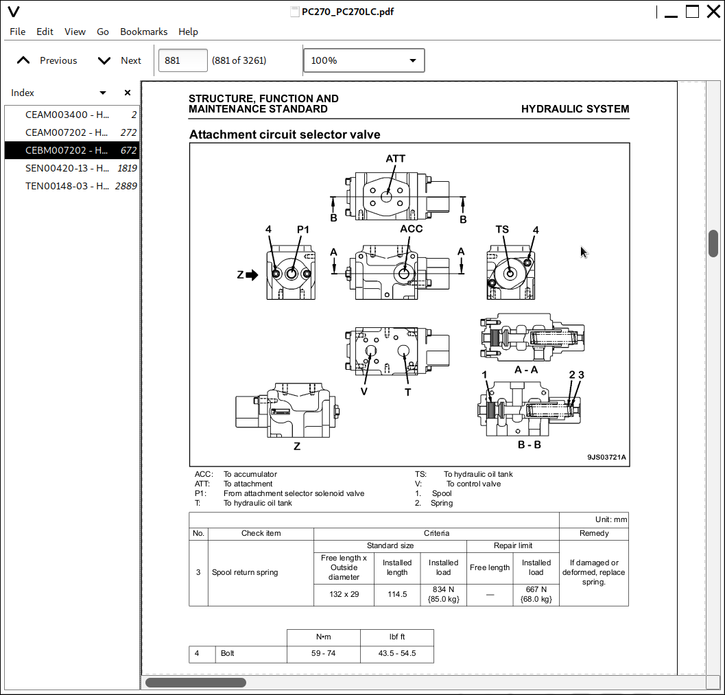
Attachment circuit selector valve...234
Hydraulic cylinder...236
Work equipment...239
Work equipment...240
Dimensions of components...240
Cab and its attachments...247
Air conditioner piping...248
Electrical system...251
Engine control...252
Electrical control system...260
Monitor system...283
Sensor...310
KOMTRAX system...313
20 Standard value table...0
Standard service value table...317
Standard service value table...318
Standard value table for engine related parts...318
Standard value table for chassis related parts...319
30 Testing and adjusting...0
Testing and adjusting, Part 1...331
Testing and adjusting, Part 1...333
Tools for testing, adjusting, and troubleshooting...333
Sketch of special tool...337
Testing engine speed...338
Testing intake air pressure (boost pressure)...339
Checking exhaust gas color...340
Adjusting valve clearance...341
Testing compression pressure...343
Testing blow-by pressure...345
Testing engine oil pressure...346
Handling fuel system parts...347
Releasing residual pressure from fuel system...347
Testing fuel pressure...348
Testing fuel delivery, return and leak amount...351
Bleeding air from fuel circuit...354
Checking fuel circuit for leakage...355
Checking and adjusting air conditioner compressor belt tension...356
Replacing fan belt...357
Testing swing circle bearing clearance...358
Checking and adjusting track shoe tension...359
Testing and adjusting oil pressure in work equipment, swing, and travel circuits...361
Testing control circuit basic pressure...364
Testing and adjusting oil pressure in pump PC control circuit...365
Testing and adjusting oil pressure in pump LS control circuit...368
Testing solenoid valve output pressure...373
Testing PPC valve output pressure...376
Adjusting play of work equipment and swing PPC valves...378
Checking parts which cause hydraulic drift of work equipment...379
Releasing residual pressure from hydraulic circuit...381
Testing oil leakage...382
Bleeding air from each part...385
Checking cab tipping stopper...387
Installation and adjustment of mirrors...388
Testing and adjusting, Part 2...393
Special functions of machine monitor...394
Testing and adjusting, Part 3...451
Testing and adjusting, Part 3...452
Handling voltage circuit of engine controller...452
Preparation work for troubleshooting of electrical system...453
Procedure for testing diodes...458
Pm Clinic service...459
40 Troubleshooting...0
Failure code table and fuse locations...467
Failure codes table...468
Fuse locations...473
General Information on troubleshooting...479
General information on troubleshooting...480
Points to remember when troubleshooting...480
Sequence of events in troubleshooting...481
Check before troubleshooting...482
Classification and procedures for troubleshooting...483
How to read electric wire code...487
Information in troubleshooting table...490
Connection table for connector pin numbers...492
T- branch box and T- branch adapter table...528
Troubleshooting by failure code (Display of code), Part 1...533
Failure code [989L00] Engine Controller Lock Caution 1...536
Failure code [989M00] Engine Controller Lock Caution 2...536
Failure code [989N00] Engine Controller Lock Caution 3...537
Failure code [AA10NX] Air Cleaner Clogging...537
Failure code [AB00KE] Charge Voltage Low...538
Failure code [B@BAZG] Eng Oil Press. Low...540
Failure code [B@BAZK] Eng Oil Level Low...540
Failure code [B@BCNS] Eng Water Overheat...541
Failure code [B@BCZK] Eng Water Level Low...541
Failure code [B@HANS] Hydr Oil Overheat...542
Failure code [CA111] EMC Critical Internal Failure...542
Failure code [CA115] Eng Ne and Bkup Speed Sens Error...543
Failure code [CA122] Chg Air Press Sensor High Error...544
Failure code [CA123] Chg Air Press Sensor Low Error...546
Failure code [CA131] Throttle Sensor High Error...548
Failure code [CA132] Throttle Sensor Low Error...550
Failure code [CA144] Coolant Temp Sens High Error...552
Failure code [CA145] Coolant Temp Sens Low Error...554
Failure code [CA153] Chg Air Temp Sensor High Error...556
Failure code [CA154] Chg Air Temp Sensor Low Error...558
Failure code [CA155] Chg Air Temp High Speed Derate...560
Failure code [CA187] Sens Supply 2 Volt Low Error...562
Failure code [CA221] Ambient Press Sens High Error...564
Failure code [CA222] Ambient Press Sens Low Error...566
Failure code [CA227] Sens Supply 2 Volt High Error...568
Failure code [CA234] Eng Overspeed...569
Failure code [CA238] Ne Speed Sens Supply Volt Error...570
Failure code [CA271] IMV/PCV1 Short Error...571
Failure code [CA272] IMV/PCV1 Open Error...572
Failure code [CA322] Inj #1 Open/Short Error...574
Failure code [CA323] Inj #5 Open/Short Error...576
Failure code [CA324] Inj #3 Open/Short Error...578
Failure code [CA325] Inj #6 Open/Short Error...580
Failure code [CA331] Inj #2 Open/Short Error...582
Failure code [CA332] Inj #4 Open/Short Error...584
Troubleshooting by failure code (Display of code), Part 2...587
Troubleshooting by failure code (Display of code), Part 2...589
Failure code [CA342] Calibration Code Incompatibility...589
Failure code [CA351] Injectors Drive Circuit Error...590
Failure code [CA352] Sens Supply 1 Volt Low Error...592
Failure code [CA386] Sens Supply 1 Volt High Error...594
Failure code [CA428] Water in Fuel Sensor High Error...596
Failure code [CA429] Water in Fuel Sensor Low Error...598
Failure code [CA435] Eng Oil Press Sw Error...600
Failure code [CA441] Battery Voltage Low Error...601
Failure code [CA442] Battery Voltage High Error...604
Failure code [CA449] Rail Press Very High Error...606
Failure code [CA451] Rail Press Sensor High Error...608
Failure code [CA452] Rail Press Sensor Low Error...610
Failure code [CA488] Chg Air Temp High Torque Derate...612
Failure code [CA553] Rail Press High Error...613
Failure code [CA559] Rail Press Low Error...614
Failure code [CA689] Eng Ne Speed Sensor Error...616
Failure code [CA731] Eng Bkup Speed Sens Phase Error...618
Failure code [CA757] All Continuous Data Lost E...620
Failure code [CA778] Eng Bkup Speed Sensor Error...622
Failure code [CA1633] KOMNET Datalink Timeout Error...624
Failure code [CA2185] Throt Sens Sup Volt High Error...625
Failure code [CA2186] Throt Sens Sup Volt Low Error...626
Failure code [CA2249] Rail Press Very Low Error...627
Failure code [CA2311] IMV Solenoid Error...628
Failure code [CA2555] Grid Htr Relay Volt High Error...630
Failure code [CA2556] Grid Htr Relay Volt Low Error...632
Failure code [D19JKZ] Personal Code Relay Abnormality...634
Failure code [D862KA] GPS Antenna Discon...636
Failure code [DA22KK] Pump Solenoid Power Low Error...638
Failure code [DA25KP] 5V Sensor 1 Power Abnormality...640
Failure code [DA29KQ] Model Selection Abnormality...646
Troubleshooting by failure code (Display of code), Part 3...649
Troubleshooting by failure code (Display of code), Part 3...651
Failure code [DA2RMC] CAN Discon (Pump Con Detected)...651
Failure code [DAF8KB] Short circuit in camera power supply...658
Failure code [DAFGMC] GPS Module Error...660
Failure code [DAFRMC] CAN Discon (Monitor Detected)...661
Failure code [DGH2KB] Hydr Oil Sensor Short...666
Failure code [DHPAMA] F Pump Press Sensor Abnormality...668
Failure code [DHPBMA] R Pump Press Sensor Abnormality...670
Failure code [DHS3MA] Arm Curl PPC Press Sensor Abnormality...672
![]()