
Komatsu Hydraulic Excavator PC210, PC210LC, PC210NLC, PC230NHD, PC240LC, PC240NLC Repair Service Manual
Complete service repair manual with Electrical Wiring Diagrams for Komatsu Hydraulic Excavator PC210-8, PC210LC-8, PC210NLC-8, PC230NHD-8, PC240LC-8, PC240NLC-8, with all the technical information to maintain, diagnose, repair, rebuild like professional mechanics.
Komatsu Hydraulic Excavator PC210-8, PC210LC-8, PC210NLC-8, PC230NHD-8, PC240LC-8, PC240NLC-8 workshop service repair manual includes:
* Numbered table of contents easy to use so that you can find the information you need fast.
* Detailed sub-steps expand on repair procedure information
* Numbered instructions guide you through every repair procedure step by step.
* Troubleshooting and electrical service procedures are combined with detailed wiring diagrams for ease of use.
* Notes, cautions and warnings throughout each chapter pinpoint critical information.
* Bold figure number help you quickly match illustrations with instructions.
* Detailed illustrations, drawings and photos guide you through every procedure.
* Enlarged inset helps you identify and examine parts in detail.
PRODUCT DETAILS:
Total Pages: 3,330 pages
File Format: PDF (Internal Links, Bookmarked, Table of Contents, Searchable, Printable, high quality)
Language: English
UEN00084-07 - Hydraulic Excavator PC210-8, PC210LC-8, PC210NLC-8, PC230NHD-8, PC240LC-8, PC240NLC-8 Shop Manual.pdf
UEN00084 - Hydraulic Excavator PC210-8, PC210LC-8, PC210NLC-8, PC230NHD-8, PC240LC-8, PC240NLC-8 Shop Manual.pdf
SEAM02050307 - Hydraulic Excavator PC200-3, PC210-3, PC220-3, PC240-3, PC280-3 Operation & Maintenance Manual.pdf
UEAM004904 - Hydraulic Excavator PC210-8, PC210LC-8, PC210NLC-8, PC230NHD-8, PC240LC-8, PC240NLC-8 Operation & Maintenance Manual.pdf
UEAM004912 - Hydraulic Excavator PC210-8, PC210LC-8, PC210NLC-8, PC230NHD-8, PC240LC-8, PC240NLC-8 Operation & Maintenance Manual.pdf
MAIN SECTIONS
00 Index and foreword...3
Index...3
Organization list of the shop manual...4
Table of contents...6
00 Index and foreword...17
Foreword and general information...17
Foreword and general information...18
Safety notice...18
How to read the shop manual...22
Explanation of terms for maintenance standard...24
Handling electric equipment and hydraulic component...26
How to read electric wire code...34
Method of disassembling and connecting push-pull type coupler...37
Standard tightening torque table...40
Conversion table...44
01 Specification...51
Specification and technical data...51
Specification and technical data...52
Specification dimension drawings...52
Working range diagram...53
Specifications...54
Weight table...58
Table of fuel, coolant and lubricants...62
10 Structure, function and maintenance standard...65
Engine and cooling system...65
Engine and cooling system...66
Engine related parts...66
Radiator, oil cooler, aftercooler and fuel cooler...67
Diesel Particulate Filter...68
Diesel Particulate Filter - Component Parts...69
System Description...70
Regeneration...70
10 Structure, function and maintenance standard...73
Power train...73
Power train...74
Power train...74
Final drive...76
Swing machinery...78
Swing circle...82
10 Structure, function and maintenance standard...85
Undercarriage and frame...85
Undercarriage and frame...86
Track frame and recoil spring...86
Idler...88
Carrier roller...90
Track roller...91
Track shoe...92
10 Structure, function and maintenance standard...99
Hydraulic system, Part 1...99
Hydraulic system, Part 1...100
Hydraulic equipment layout drawing...100
Hydraulic tank and filter...102
Hydraulic pump...103
Hydraulic pump...104
Pilot oil filter...127
10 Structure, function and maintenance standard...129
Hydraulic system, Part 2...129
Hydraulic system, Part 2...130
Control valve...130
CLSS...143
Functions and operation by valve...148
Hydraulic drift prevention valve...174
10 Structure, function and maintenance standard...187
Hydraulic system, Part 3...187
Hydraulic system, Part 3...189
Swing motor...189
Centre swivel joint...198
Travel motor...201
PPC valve...212
Valve control...232
ATT EPC Valve Assembly...234
Solenoid valve...236
PPC Accumulator...238
Return oil filter...239
Attachment circuit selector valve...240
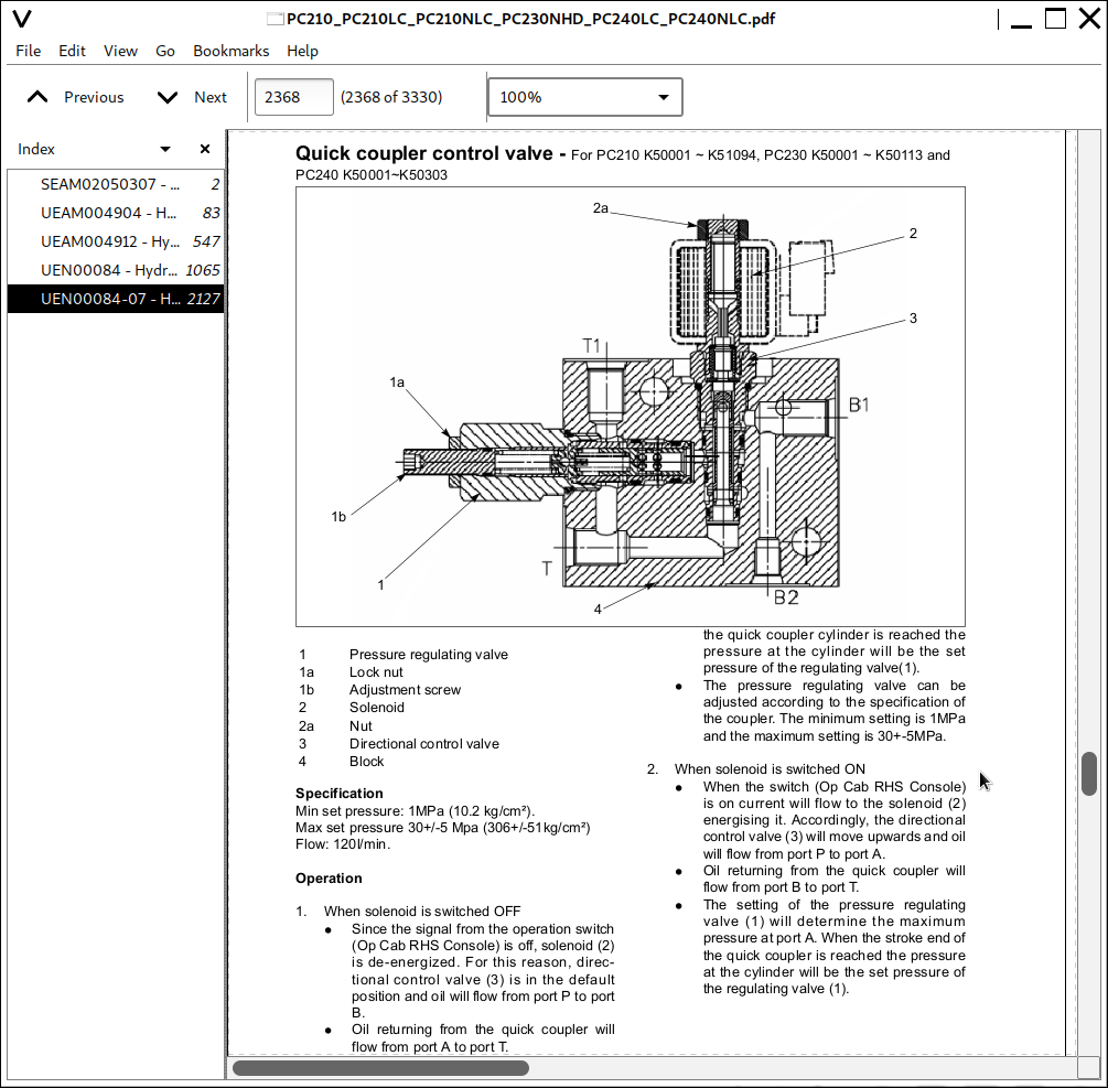
Quick coupler control valve - For PC210 K50001 ~ K51094, PC230 K50001 ~ K50113 and PC240 K50001~K50303...242
Quick coupler control valve - For PC210 K51095 - K53243, PC230 K50114 - K50286 and PC240 K50304 - K51093.)...244
Quick coupler control valve - For PC210 K53424 and up, PC230 K50287 and up and PC240 K51094 and up...246
Hydraulic cylinder...248
10 Structure, function and maintenance standard...253
Work equipment...253
Work equipment...254
Dimensions of components...254
10 Structure, function and maintenance standard...261
Cab and its attachments...261
Cab and its attachments...262
Air conditioner piping...262
10 Structure, function and maintenance standard...265
Electrical system...265
Electrical system...266
Engine control...266
Electrical control system...274
Monitor system...300
Sensor...331
PPC Levers...334
KOMTRAX terminal system...336
10 Structure, function and maintenance standard...339
Auto Grease system...339
Outline of Auto Grease System...340
20 Standard value table...355
Standard service value table...355
Standard service value table...356
Standard value table for engine related parts...356
Standard value table for chassis related parts...358
30 Testing and adjusting...377
Testing and adjusting, Part 1...377
Testing and adjusting, Part 1...379
Tools for testing, adjusting, and troubleshooting...379
Measuring engine speed...382
Measuring intake air pressure (boost pressure)...383
Checking exhaust gas colour...384
Adjusting valve clearance...385
Measuring compression pressure...387
Measuring blow-by pressure...389
Measuring engine oil pressure...390
Handling fuel system parts...391
Releasing residual pressure from fuel system...391
Measuring fuel pressure...392
Measuring fuel return rate and leakage...394
Bleeding air from fuel circuit...396
Checking fuel circuit for leakage...398
Checking and adjusting air conditioner compressor belt tension...399
Measuring swing circle bearing clearance...400
Checking and adjusting track shoe tension...401
Measuring and adjusting oil pressure in work equipment, swing, and travel circuits...403
Measuring control circuit basic pressure...407
Measuring and adjusting oil pressure in pump PC control circuit...408
Measuring and adjusting oil pressure in pump LS control circuit...412
Measuring solenoid valve output pressure...418
Measuring PPC valve output pressure...421
Adjusting play of work equipment and swing PPC valves...423
Measuring and adjusting quick coupler control valve output pressure - For PC210 K50001 - K53423, PC230 K50001 - K50286 and PC240 K50001 - K51093...424
Measuring and adjusting quick coupler control valve output pressure - For PC210 K53424 and up, PC230 K50287 and up and PC240 K51094 and up...425
Checking parts which cause hydraulic drift of work equipment...426
Releasing residual pressure from hydraulic circuit...428
Measuring oil leakage...429
Bleeding air from each part...432
Checking cab tipping stopper...435
Adjusting mirrors...436
Adjusting mirrors...438
30 Testing and adjusting...441
Testing and adjusting, Part 2...441
Testing and adjusting, Part 2...442
Special functions of machine monitor...442
30 Testing and adjusting...507
Testing and adjusting, Part 3...507
Testing and adjusting, Part 3...508
Handling high-voltage circuit of engine controller...508
Preparation work for troubleshooting of electrical system...509
Procedure for testing diodes...513
Pm Clinic service...515
Warning...517
Pm Clinic service...521
40 Troubleshooting...529
General information on troubleshooting...529
General information on troubleshooting...530
Points to remember when troubleshooting...530
Sequence of events in troubleshooting...531
Check before troubleshooting...532
Classification and procedures for troubleshooting...533
How to read electric wire code...537
Connection table for connector pin numbers...540
T-boxes and T-adapters table...571
40 Troubleshooting...577
Troubleshooting by failure code (Display of code), Part 1...577
Troubleshooting by failure code (Display of code), Part 1...579
Failure codes table...579
Before carrying out troubleshooting when failure code is displayed...584
Before carrying out troubleshooting when failure code is displayed...585
Information in troubleshooting table...590
Failure code [989L00] Engine Controller Lock Caution 1...592
Failure code [989M00] Engine Controller Lock Caution 2...592
Failure code [989N00] Engine Controller Lock Caution 3...593
Failure code [AA10NX] Air Cleaner Clogging...593
Failure code [AB00KE] Charge Voltage Low...594
Failure code [B@BAZG] Eng Oil Press. Low...596
Failure code [B@BAZK] Eng Oil Level Low...596
Failure code [B@BCNS] Eng Water Overheat...597
Failure code [B@BCZK] Eng Water Level Low...597
Failure code [B@HANS] Hydr Oil Overheat...598
Failure code [CA111] EMC Critical Internal Failure...598
Failure code [CA115] Eng Ne and Bkup Speed Sens Error...599
Failure code [CA122] Chg Air Press Sensor High Error...600
Failure code [CA123] Chg Air Press Sensor Low Error...602
Failure code [CA131] Throttle Sensor High Error...604
Failure code [CA132] Throttle Sensor Low Error...606
Failure code [CA144] Coolant Temp Sens High Error...608
Failure code [CA145] Coolant Temp Sens Low Error...610
Failure code [CA153] Chg Air Temp Sensor High Error...612
Failure code [CA154] Chg Air Temp Sensor Low Error...614
Failure code [CA155] Chg Air Temp High Speed Derate...616
Failure code [CA187] Sens Supply 2 Volt Low Error...618
Failure code [CA221] Ambient Press Sens High Error...620
Failure code [CA222] Ambient Press Sens Low Error...622
Failure code [CA227] Sens Supply 2 Volt High Error...624
Failure code [CA234] Eng Overspeed...625
Failure code [CA238] Ne Speed Sens Supply Volt Error...626
Failure code [CA271] IMV/PCV1 Short Error...627
Failure code [CA272] IMV/PCV1 Open Error...628
Failure code [CA322] Inj #1 (L#1) Open/Short Error...630
![]()