
Komatsu Hydraulic Excavator PC200, PC200LC, PC220, PC220LC Repair Service Manual + Operation & Maintenance Manual
Complete service repair manual with Electrical Wiring Diagrams for Komatsu Hydraulic Excavator PC200-2, PC200-6, PC200LC-2, PC200LC-6, PC200LC-8, PC220-2, PC220LC-2, with all the technical information to maintain, diagnose, repair, and rebuild like professional mechanics.
Komatsu Hydraulic Excavator PC200-2, PC200-6, PC200LC-2, PC200LC-6, PC200LC-8, PC220-2, PC220LC-2 workshop service repair manual includes:
* Numbered table of contents easy to use so that you can find the information you need fast.
* Detailed sub-steps expand on repair procedure information
* Numbered instructions guide you through every repair procedure step by step.
* Troubleshooting and electrical service procedures are combined with detailed wiring diagrams for ease of use.
* Notes, cautions and warnings throughout each chapter pinpoint critical information.
* Bold figure number help you quickly match illustrations with instructions.
* Detailed illustrations, drawings and photos guide you through every procedure.
* Enlarged inset helps you identify and examine parts in detail.
PRODUCT DETAILS:
Total Pages: 4,613 pages
File Format: PDF (Internal Links, Bookmarked, Table of Contents, Searchable, Printable, high quality)
Language: English
CEBM025500 - Hydraulic Excavator PC200LC-8 Shop Manual.pdf
SEBM0205B04 - Hydraulic Excavator PC200-2, PC200LC-2, PC220-2, PC220LC-2 Shop Manual.pdf
SEBM010201 - Hydraulic Excavator PC200-6 Shop Manual.pdf
SEBM010202 - Hydraulic Excavator PC200LC-6 Shop Manual.pdf
CEAM025700 - Hydraulic Excavator PC200LC-8 Latin America Operation & Maintenance Manual.pdf
SEAM016301 - Hydraulic Excavator PC200-6 Operation & Maintenance Manual.pdf
SEAM021701 - Hydraulic Excavator PC200-6 avance Series Operation & Maintenance Manual.pdf
SEAM023800PT - Hydraulic Excavator PC200-6, PC200LC-6 Operation & Maintenance Manual.pdf
SEAM045200ATH - Hydraulic Excavator GALEO PC200-7, PC200LC-7 Operation & Maintenance Manual.pdf
TEN00205-00 - Hydraulic Excavator PC200-8, PC200LC-8 Operation & Maintenance Manual.pdf
MAIN SECTIONS
CEBM025500 PC200LC-8 LATIN AMERICA...1
CONTENTS...2
GENERAL...5
HOW TO READ THE SHOP MANUAL...6
Volumes...6
Distribution And Updating...6
Filing Method...6
Revised Edition Mark...6
Revisions...6
Symbols...6
HOISTING INSTRUCTIONS...7
Hoisting...7
Wire Ropes...7
PUSH PULL COUPLER...8
Type 1...8
Disconnection...8
Connection...8
Type 2...9
Disconnection...9
Connection...9
Type 3...10
Disconnection...10
Connection...10
COATING MATERIALS...11
STANDARD TIGHTENING TORQUE...14
Standard Tightening Torque Of Bolts And Nuts...14
Tightening Torque Of Hose Nuts...15
Tightening Torque Of Split Flange Bolts...15
Tightening Torque For Flared Nuts...15
Table Of Tightening Torques For O-ring Boss Piping Joints...16
Table Of Tightening Torques For O-ring Boss Plugs...16
Tightening Torque Table For Hoses (Taper Seal Type And Face Seal Type)...16
ELECTRIC WIRE CODE...17
Classification By Thickness...17
Classification By Color And Code...17
CONVERSION TABLES...18
Method Of Using The Conversion Table...18
01 GENERAL...25
SPECIFICATION AND TECHNICAL DATA...26
Specification Dimension Drawings...26
Working Range Diagram...27
Specifications...28
Weight Table...30
Table Of Fuel, Coolant And Lubricants...32
Recommended Brands, Recommended Quality For Products Other Than Komatsu Genuine Oil...33
10 STRUCTURE, FUNCTION AND MAINTENANCE STANDARD...35
ENGINE AND COOLING SYSTEM...39
Engine Related Parts...39
Radiator, Oil Cooler, Aftercooler and Fuel Cooler...40
POWER TRAIN...41
Power Train...41
Final Drive...42
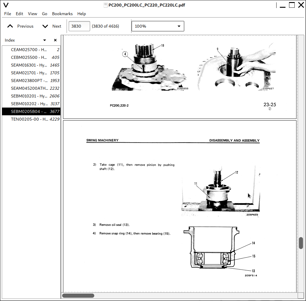
Swing Machinery...44
Swing Circle...46
UNDERCARRIAGE AND FRAME...48
Track Frame And Recoil Spring...48
Standard Shoe...49
Idler...50
Carrier Roller...52
Track Roller...54
Track Shoe...56
Triple Grouser Shoe...59
HYDRAULIC SYSTEM...60
Hydraulic Equipment Layout Drawing...60
Hydraulic Tank And Filter...62
Hydraulic Pump...64
Type: HPV95+95...64
Operation of pump...69
Control of delivery...70
LS Valve...71
PC Valve...77
LS (PC)-EPC Valve...84
Pilot Oil Filter...87
For breaker...87
Control Valve...89
Outline...89
General View...90
Sectional View...92
CLSS...102
Outline of CLSS...102
LS Differential Pressure and Pump Swash Plate Angle...103
Functions and Operation by Valve...106
Hydraulic Circuit Diagram and the Name of Valves...106
Unload Valve...108
Introduction Of LS Pressure...110
LS Bypass Plug...111
Pressure Compensation Valve...112
Integrated Pressure Compensation Valve...113
Pressure Compensation Valve Inner Shuttle Valve...115
Boom Regeneration Circuit...117
Arm Regeneration Circuit...119
Merge-divider Valve...121
LS Select Valve...124
Self Pressure Reducing Valve...125
Travel Junction Valve...128
Travel PPC Shuttle Valve...130
Boom Drift Prevention Valve...133
Arm Drift Prevention Valve (if equipped)...136
Quick Return Valve...140
Lift Check Valve...143
Main Relief Valve...144
2-stage Safety-suction Valve...145
Swing Motor...148
Torque Values...149
Specifications...149
Swing Holding Brake...152
Relief Valve Portion...153
Outline...153
Reverse Prevention Valve...154
Center Swivel Joint...158
Travel Motor...160
Operation Of Motor...164
Operation of Parking Brake...166
Brake Valve...168
Operation When Pressurized Oil is Supplied...168
Operation of Brake During Traveling Downhill...169
PPC Valve...172
Work Equipment and Swing PPC Valve...172
Travel PPC Valve...178
Pressure reducing valve function...182
Travel Signal/steering Function...184
Service PPC Valve (With EPC Valve)...190
EPC valve...192
When Signal Current Is 0...194
When Signal Current is Very Small...194
When Signal Current Is Maximum...195
Service PPC Valve...196
Valve Control...198
Lever Positions...199
Solenoid Valve...200
When Solenoid is De-energized...201
When Solenoid is Energized...202
PPC Accumulator...203
Specifications...203
CRN (Canadian certified) PPC Accumulator...203
Return Oil Filter...204
Attachment Circuit Selector Valve...205
When Attachment Other Than Breaker is Installed...206
When Breaker is Installed...206
Hydraulic Cylinder...208
PC200LC-8...208
WORK EQUIPMENT...210
Dimensions of Components...210
PC200LC-8...211
CAB AND ITS ATTACHMENTS...217
Air Conditioner Piping...217
ELECTRICAL SYSTEM...218
Engine Control...218
Operation of system...218
Component...219
Fuel Control Dial...219
Engine Controller...220
Coolant Temperature Sensor...223
Oil Pressure Switch...223
Rotation Sensor...224
Boost Pressure and Temperature Sensor...224
WIF (Water-in-fuel Detection) Sensor...225
Engine Oil Level Sensor...225
Electrical Control System...227
Machine Control System Diagram...227
MONITOR SYSTEM...251
Machine Monitor...252
Input And Output Signals...253
Monitor Control, Display Portion...255
Precautions on the Machine Monitor Display...256
Monitor Items and Display...257
Switches...261
Buzzer Cancel Switch...261
Auto-deceleration Switch...261
Guidance Icon And Function Switch...261
Working Mode Selector Switch...263
Travel Speed Selector Switch...263
Window Washer Switch...264
Wiper Switch...264
Air Conditioner Control Switch...264
Camera Screen Display Function...265
Service Meter/Time Selector Function...266
Maintenance Function...266
User Mode...268
Breaker/Attachment Setting...268
Changing Breaker Mode Setting...269
Changing Attachment Mode Setting...271
Message Display...272
Screen Adjustment...273
Clock Adjustment...273
Language Setting...274
Economy Mode Adjustment...274
Idle Stop Guidance Function...275
Service Meter Check Function...275
Display LCD Check Function...275
User Code/Failure Code Display Function...276
SENSOR...277
Fuel Level Sensor...277
Air Cleaner Clogging Sensor...278
Coolant Level Sensor...278
KOMTRAX TERMINAL SYSTEM...279
KOMTRAX Communication ORBCOMM...280
TH300...280
Input And Output Signals...280
20 STANDARD VALUE TABLES...281
STANDARD SERVICE VALUE TABLE...283
Standard Service Value Table for Engine...283
Standard Value Table for Chassis Related Parts...284
Machine Position for Measurement...291
Control Valve: Spool Stroke...291
Swing 1: Swing Brake Angle, Time Taken To Start Swing, Time Taken To Swing...291
Swing 2: Hydraulic Drift Of Swing...291
Travel 1: Travel Speed (Without Load)...291
Travel 2: Travel Speed (Actual Run), Travel Deviation...292
Travel 3: Travel Deviation...292
Travel 4: Hydraulic Drift Of Travel...292
Work Equipment 1: Hydraulic Drift Of Work Equipment...292
Work Equipment 2: Boom Speed...293
Work Equipment 3: Arm Speed...293
Work Equipment 4: Bucket Speed...293
Work Equipment 5: Boom Time Lag...293
Work Equipment 6: Arm Time Lag...294
Work Equipment 7: Bucket Time Lag...294
Work Equipment 8: Characteristics Of PC Flow Control Valve...294
30 TESTING AND ADJUSTING...295
SPECIAL TOOL LIST...298
Sketch Of Special Tool...301
ENGINE COMPONENTS...302
Determining A Defective Cylinder...302
Procedures...302
Determining Cylinder Group...302
Isolating the Defective Cylinder...302
Water Pump Leakage...303
Engine Speed...308
Intake Air Pressure (Boost Pressure)...310
Exhaust Gas Color...311
Valve Clearance...313
Compression Pressure...315
Blow-by Pressure...317
Engine Oil Pressure...318
Handling Fuel System Parts...319
Releasing Residual Pressure From Fuel System...319
Fuel Pressure...320
Fuel Return Rate And Leakage...323
Bleeding Air From Fuel Circuit...328
Fuel Circuit - Checking For Leakage...329
AIR CONDITIONER COMPRESSOR BELT TENSION...330
Checking...330
Adjusting...330
FAN BELT...331
SWING CIRCLE BEARING CLEARANCE...332
TRACK SHOE TENSION...334
Checking...334
Adjusting...334
OIL PRESSURE IN WORK EQUIPMENT, SWING, AND TRAVEL CIRCUITS...336
Measuring...336
Adjusting...339
CONTROL CIRCUIT BASIC PRESSURE...341
OIL PRESSURE IN PUMP PC CONTROL CIRCUIT...343
Measuring...343
Adjusting...345
Pump PC Valve...345
OIL PRESSURE IN PUMP LS CONTROL CIRCUIT...346
Measuring...346
Adjusting...350
LS valve...350
SOLENOID VALVE OUTPUT PRESSURE...351
PPC VALVE OUTPUT PRESSURE...354
Connecting Points Of PPC Piping...354
Adjusting Play of Work Equipment and Swing PPC Valves...356
WORK EQUIPMENT HYDRAULIC DRIFT...357
RELEASING RESIDUAL PRESSURE FROM HYDRAULIC CIRCUIT...359
OIL LEAKAGE...360
BLEEDING AIR FROM EACH PART...363
CAB TIPPING STOPPER...365
MIRRORS...366
REAR VIEW CAMERA...369
Angle Adjustment...369
MACHINE MONITOR SPECIAL FUNCTIONS...371
Air Conditioner Specification...371
Upper Section of Machine Monitor...372
Display Section...372
Switch Section...372
Lower Section Of Machine Monitor...372
Switch Section...372
Ordinary Functions and Special Functions of Machine Monitor...373
Operator Mode (Outline)...375
Display of KOMATSU Logo...376
Display of Inputting Password...376
Display of Check of Breaker Mode...376
Display of Check Before Starting...377
Display of Warning After Check Before Starting...377
Display of Ending of Maintenance Interval...377
Display of Check of Working Mode and Travel Speed...377
Display of Ordinary Screen...378
Display of End Screen...378
Selection of Auto-Deceleration...378
Selection of Working Mode...378
Selection of Travel Speed...380
Operation to Stop Alarm Buzzer...380
Operation of Windshield Wiper...380
Operation of Window Washer...380
Operation of Air Conditioner/heater...380
Operation to Display Camera Mode (If Camera is Installed)...381
Operation to Display Clock and Service Meter...382
Check of Maintenance Information...382
Setting and Display of User Mode (Including KOMTRAX Messages for User)...383
KOMTRAX Message...384
Display of Energy-Saving Guidance...384
Display of Caution Monitor...384
Display of Automatic Judgment of Breaker...384
Display of User Code and Failure Code...385
Function of Checking Display of LCD (Liquid Crystal Display)...386
Function of Checking Service Meter...386
Function of Changing Attachment/Maintenance Password...386
Service Mode...388
Monitoring...389
Monitoring Items Table...392
Abnormality Record (Mechanical Systems)...395
Abnormality Record (Electrical Systems)...396
Failure Codes Table...398
Abnormality Record (Air-Conditioning System/ Heater System)...402
Maintenance Record...403
Maintenance Mode Change...404
Phone Number Entry...406
Default (Key-on Mode)...407
Default (Unit)...408
Default (With/Without Attachment)...409
Default (Attachment/Maintenance Password)...410
Default (Camera)...411
Default (ECO Display)...412
Default (Breaker Detect)...414
Adjustment (Pump Absorption Torque (F))...415
Adjustment (Pump Absorption Torque (R))...416
Adjustment (Low Speed)...417
Adjustment (Attachment Flow Adjustment)...418
Cylinder Cut-Out...419
No Injection...420
Fuel Consumption...422
KOMTRAX Settings (Terminal Status)...423
KOMTRAX Settings (GPS & Communication Status)...424
KOMTRAX Setting (MODEM S/N: TH300)...425
![]()