
Komatsu Hydraulic Excavator PC200, PC200LC, PC210, PC210LC, PC220, PC220LC, PC230, PC230LC Repair Service Manual + Operation & Maintenance Manual
Complete service repair manual with Electrical Wiring Diagrams for Komatsu Hydraulic Excavator PC200-6, PC200LC-6, PC210-6, PC210LC-6, PC220-6, PC220LC-6, PC230-6, PC230LC-6, with all the technical information to maintain, diagnose, repair, rebuild like professional mechanics.
Komatsu Hydraulic Excavator PC200-6, PC200LC-6, PC210-6, PC210LC-6, PC220-6, PC220LC-6, PC230-6, PC230LC-6 workshop service repair manual includes:
* Numbered table of contents easy to use so that you can find the information you need fast.
* Detailed sub-steps expand on repair procedure information
* Numbered instructions guide you through every repair procedure step by step.
* Troubleshooting and electrical service procedures are combined with detailed wiring diagrams for ease of use.
* Notes, cautions and warnings throughout each chapter pinpoint critical information.
* Bold figure number help you quickly match illustrations with instructions.
* Detailed illustrations, drawings and photos guide you through every procedure.
* Enlarged inset helps you identify and examine parts in detail.
PRODUCT DETAILS:
Total Pages: 2,665 pages
File Format: PDF (Internal Links, Bookmarked, Table of Contents, Searchable, Printable, high quality)
Language: English
SEBM010106 - Hydraulic Excavator PC200-6, PC200LC-6, PC210-6, PC210LC-6, PC220-6, PC220LC-6, PC230-6, PC230LC-6 Shop Manual.pdf
SEAM002403 - Hydraulic Excavator PC200-6, PC200LC-6, PC210-6 Mighty, PC210LC-6 Mighty, PC220-6, PC220LC-6, PC230-6 Mighty, PC230LC-6 Mighty Operation & Maintenance Manual.pdf
SEAM002405 - Hydraulic Excavator PC200-6, PC200LC-6, PC210-6 Mighty, PC210LC-6 Mighty, PC220-6, PC220LC-6, PC230-6 Mighty, PC230LC-6 Mighty Operation & Maintenance Manual.pdf
SEAM002406 - Hydraulic Excavator PC200-6, PC200LC-6, PC210-6 Mighty, PC210LC-6 Mighty, PC220-6, PC220LC-6, PC230-6 Mighty, PC230LC-6 Mighty Operation & Maintenance Manual.pdf
SEAM002407 - Hydraulic Excavator PC200-6, PC200LC-6, PC210-6 Mighty, PC210LC-6 Mighty, PC220-6, PC220LC-6, PC230-6 Mighty, PC230LC-6 Mighty Operation & Maintenance Manual.pdf
SEAM002410T - Hydraulic Excavator PC200-6, PC200LC-6, PC210-6 Mighty, PC210LC-6 Mighty, PC220-6, PC220LC-6, PC230-6 Mighty, PC230LC-6 Mighty Operation & Maintenance Manual.pdf
MAIN SECTIONS
MAIN MENU...0
COVER...1
CONTENTS...2
SAFETY...11
Safety Notice...11
FOREWORD...13
General...13
How to Read the Shop Manual...14
Hoisting Instructions...15
Method of Disassembling, Connecting Push-Pull Type Coupler...16
Coating Materials...18
Standard Tightening Torque...20
Electric Wire Code...23
Conversion Table...24
Units...30
01 GENERAL...31
Specification Dimension Drawings...32
Specifications...40
Weight Table...62
Fuel, Coolant and Lubricants...82
10 STRUCTURE AND FUNCTION...85
Engine Related Parts...86
Radiator, Oil Cooler, Aftercooler...88
Power Train...91
Final Drive...92
Swing Circle...93
Swing Machinery...94
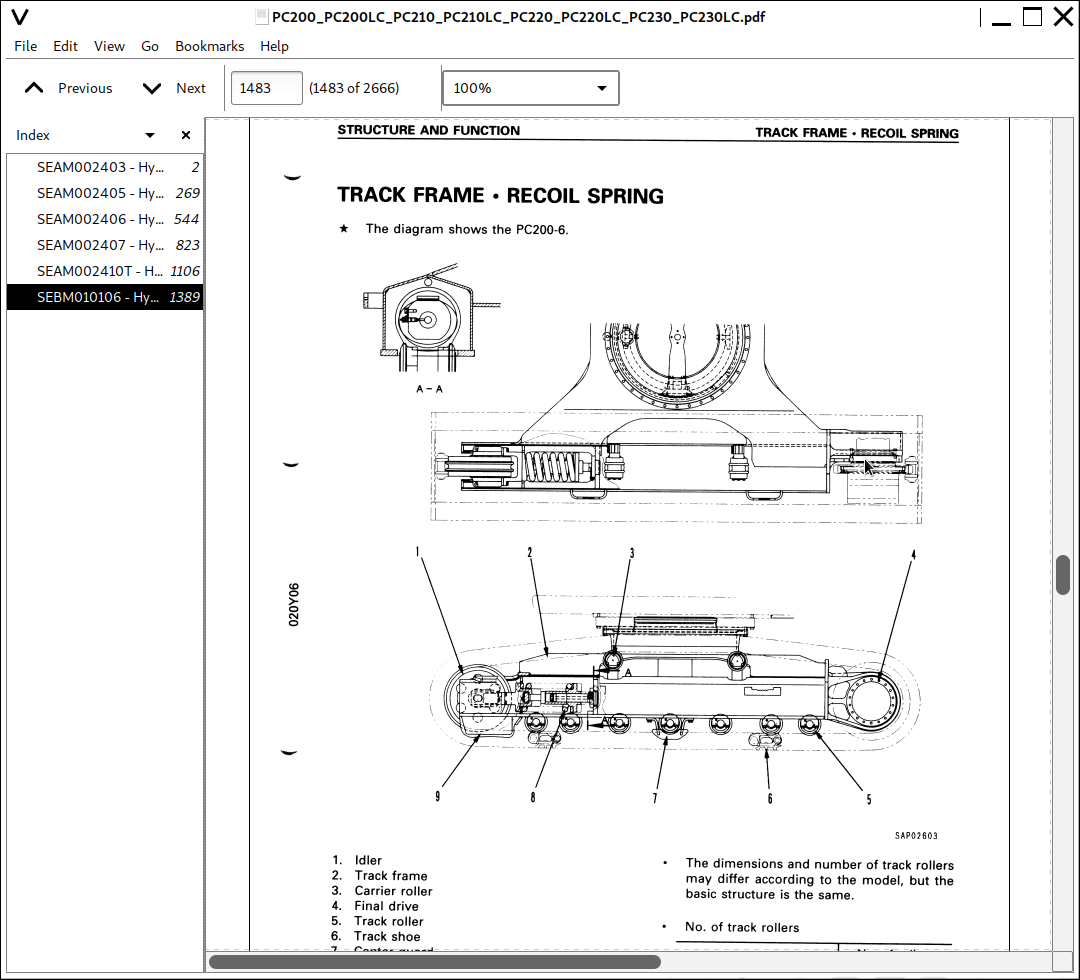
Track Frame, Recoil Spring...95
Track Shoe...96
Hydraulic Piping Drawing...98
Hydraulic Circuit Diagram...102
Hydraulic Tank...106
Hydraulic Pump...107
Line Oil Filter...139
Control Valve...140
Self-reducing Pressure Valve...154
CLSS...159
Swing Motor...222
Center Swivel Joint...228
Travel Motor...230
Valve Control...238
Work Equipment, Swing PPC Valve...240
Travel PPC Valve...248
Service PPC Valve...252
Safety Lock Valve...256
PPC Accumulator...256
Straight-Travel System...257
Solenoid Valve...258
Boom Holding Valve...260
Additional Filter for Breaker...263
Swivel Joint for Arm Rotation...265
Arm Rotation Motor...266
Work Equipment...268
Air Conditioner...269
Actual Electric Wiring Diagram...270
Electrical Circuit Diagram...278
PC220-6 STD Serial No.: 96514 - 102228...278
PC210-6 STD Serial No.: 30980 - 31424...278
PC220-6 STD Serial No.: 52852 - 53561...278
PC230-6 STD Serial No.: 10177 - 10246...278
Engine Control System...292
Electronic Control System for STD...301
Electronic Control System for Hyper GX...341
Machine Monitor System...400
Sensors...411
Front Window Auto Pull-up System...414
20 TESTING AND ADJUSTING...417
TABLE OF JUDGEMENT STANDARD VALUE...420
TESTING AND ADJUSTING...445
Tools for Testing, Adjusting, and Troubleshooting...445
Measuring Engine Speed...446
Measuring Exhaust Gas Color...447
Adjusting Valve Clearance...448
Measuring Compression Pressure...449
Measuring Blow-by Pressure...449
Testing and Adjusting Fuel Injection Timing...450
Measuring Engine Oil Pressure...451
Testing and Adjusting Alternator Belt Tension...452
Testing and Adjusting Belt Tension for Air Conditioner Compressor...452
Measuring Speed Sensor...453
Testing and Adjusting Governor Motor Lever Stroke...454
Testing and Adjusting Hydraulic Pressure in Work Equipment, Swing, Travel Circuit...455
Testing and Adjusting PC Valve Output Pressure (Servo Piston Input Pressure)...458
Testing and Adjusting LS Valve Output Pressure (Servo Piston Input Pressure) and LS Differential Pressure...460
Testing and Adjusting Control Circuit Oil Pressure...463
Testing Solenoid Valve Output Pressure...465
Measuring PPC Valve Output Pressure...467
Measuring EPC Solenoid Valve Output Pressure and Checking EPC Shuttle Valve...469
Adjusting Work Equipment, Swing PPC Valve...471
Testing Travel Deviation...472
Testing Locations Causing Hydraulic Drift of Work Equipment...473
Measuring Oil Leakage...475
Releasing Remaining Pressure in Hydraulic Circuit...477
Testing Clearance of Swing Circle Bearing...478
Testing and Adjusting Track Shoe Tension...479
Bleeding Air...480
Input/Output Structure of GX Controller...483
Basic Operation and GX Function...484
Special Functions on GX Panel (Background Mode)...486
Check Procedure when Operation of GX Automatic Function is Defective...509
Adjusting Swing Back Prevention Function (Swing Teaching Mode)...511
Bucket Dimension Input Mode when Using Custom Bucket...513
Procedure for Replacing Sensor...516
TROUBLESHOOTING...522
Points to Remember When Troubleshooting...523
Sequence of Events in Troubleshooting...524
Precautions When Carrying Out Maintenance...525
Checks Before Troubleshooting...533
Connector Types and Mounting Locations...535
Connection Table for Connector Pin Numbers...543
Explanation of Control Mechanism for Electrical System...555
Display Method and Special Functions of Monitor Panel...557
Method of Using Judgement Table...567
Method of Using Troubleshooting Charts...569
Details of Troubleshooting and Troubleshooting Procedure...571
Troubleshooting of Communication Abnormality System ( N Mode)...578
N-1 (E218) Communications Abnormality...579
Troubleshooting of Engine Throttle - Pump Controller (Govenor Control System) (E Mode)...582
Points to Remember When Carrying Out Troubleshooting of Engine Throttle - Pump Controller System...583
Action Taken by Controller When Abnormality Occurs and Problems on Machine...585
Judgement Table for Engine Throttle - Pump Controller (Govenor Control System) and Engine Related Parts...589
Electrical Circuit Diagram for E Mode System...591
E-1 Abnormality in Engine Throttle - Pump Controller Power Source (controller LED is OFF)...593
E-2 (E308) Abnormality in Fuel Control Dial Imput Value is Displayed...594
E-3 (E317) Abnormality (disconnection) in Motor Drive System is Displayed...595
E-4 (E318) Abnormality (short circuit) in Motor Drive System is Displayed...596
E-5 (E306) Abnormality in Feedback Potentionmeter System is Displayed...597
E-6 (E315) Abnormality (short circuit) in Battery Relay Output System is Displayed...598
E-7 (E316) Abnormality (step-out) in Motor is Displayed...599
E-8 Engine Does Not Start...601
E-9 Engine Speed is Irregular...605
a) Idling Speed is Irregular...605
b) There is Hunting...607
E-10 Lack of Output (engine high idling speed is too low)...609
E-11 Engine Does Not Stop...611
E-12 Defective Operation of Battery Relay System (engine does not stop)...613
Troubleshooting of Engine System (S Mode)...616
Method of Using Troubleshooting Charts...617
S-1 Starting Performance is Poor (starting always takes time)...621
S-2 Engine Does Not Start...622
(1) Engine Does Not Turn...622
(2) Engine Turns But no Exhaust Smoke Comes Out (fuel is not being injected)...623
(3) Exhaust Smoke Comes Out but Engine Does Not Start (fuel is being injected)...624
S-3 Engine Does Not Pick Up Smoothly (follow-up is poor)...625
S-4 Engine Stops During Operation...626
S-5 Engine Does Not Rotate Smoothly (hunting)...627
S-6 Engine Lacks Output ( no power)...628
S-7 Exhaust Smoke is Black (incomplete combustion)...629
S-8 Oil Consumption is Excessive (or exhaust smoke is blue)...630
S-9 Oil Becomes Contaminated Quickly...631
S-10 Fuel Consumption is Excessive...632
S-11 Oil is in Cooling Water, or Water Spurts Back, or Water Level Goes Down...633
S-12 Oil Pressure Caution Lamp Lights Up (drop in oil pressure)...634
S-13 Oil Level Rises (water, fuel in oil)...635
S-14 Water Temperature Becomes Too High (overheating)...636
S-15 Abnormal Noise is Made...637
S-16 Vibration is Excessive...638
Troubleshooting of Engine Throttle - Pump Controller (Pump Control System) (C Mode)...640
Points to Remember When Troubleshooting Pump Controller System...641
Action Taken by Controller When Abnormality Occurs and Problems on Machine...643
Judgement Table for Engine Throttle - Pump Controller (pump control system) and Hydraulic Related Parts...651
Electrical Circuit Diagram for C Mode...653
C-1 Abnormality in Controller Power Source System (controller LED is OFF)...657
C-2 (E232) Short Circuit in PC-EPC Solenoid System is Displayed...658
C-3 (E233) Disconnection in PC-EPC Solenoid System is Displayed...659
C-4 (E203) Short Circuit in Swing Brake Solenoid System is Displayed...660
C-5 (E213) Disconnection in Swing Brake Solenoid System is Displayed...662
C-6 (E204) Short Circuit in Pump Merge/Divider Solenoid System is Displayed...664
C-7 (E214) Disconnection in Pump Merge/Divider Solenoid System is Displayed...665
C-8 (E207) Short Circuit In Active Mode Solenoid System is Displayed...666
C-9 (E208) Disconnection in Active Mode Solenoid System is Displayed...667
C-10 (E206) Short Circuit in Travel Speed Solenoid System is Displayed...668
C-11 (E216) Disconnection in Travel Speed Solenoid System is Displayed...669
C-12 (E205) Short Circuit in 2-Stage Relief Solenoid System is Displayed...670
C-13 (E215) Disconnection in 2-State Relief Solenoid System is Displayed...671
C-14 (E217) Model Selection Input Error is Displayed...672
C-15 (E222) Short Circuit in LS-EPC Solenoid System is Displayed...674
C-16 (E223) Disconnection in LS-EPC Solenoid System is Displayed...675
C-17 (E224) Abnormality in Front Pump Pressure Sensor System is Displayed...676
![]()