
Komatsu Hydraulic Excavator PC200, PC200LC, PC210LC, PC220, PC240LC Repair Service Manual
Complete service repair manual with Electrical Wiring Diagrams for Komatsu Hydraulic Excavator PC200-3, PC200-8, PC200LC-8, PC210LC-3, PC220-3, PC240LC-3, PC240LC-8, with all the technical information to maintain, diagnose, repair, rebuild like professional mechanics.
Komatsu Hydraulic Excavator PC200-3, PC210LC-3, PC220-3, PC240LC-3, PC200-8, PC200LC-8, PC240LC-8 workshop service repair manual includes:
* Numbered table of contents easy to use so that you can find the information you need fast.
* Detailed sub-steps expand on repair procedure information
* Numbered instructions guide you through every repair procedure step by step.
* Troubleshooting and electrical service procedures are combined with detailed wiring diagrams for ease of use.
* Notes, cautions and warnings throughout each chapter pinpoint critical information.
* Bold figure number help you quickly match illustrations with instructions.
* Detailed illustrations, drawings and photos guide you through every procedure.
* Enlarged inset helps you identify and examine parts in detail.
PRODUCT DETAILS:
Total Pages: 2,724 pages
File Format: PDF (Internal Links, Bookmarked, Table of Contents, Searchable, Printable, high quality)
Language: English
KEN00084-13 - Hydraulic Excavator PC200-8, PC200LC-8, PC240LC-8 Shop Manual.pdf
SEBM02050309 - Hydraulic Excavator PC200-3, PC210LC-3, PC220-3, PC240LC-3 Shop Manual.pdf
KEAM042800 - Hydraulic Excavator PC200-8, PC200LC-8, PC240LC-8 Operation & Maintenance Manual.pdf
KPAM042800 - Escavadeiras Hidráulicas PC200-8, PC200LC-8, PC240LC-8 Manual de Operação e Manutenção.pdf
MAIN SECTIONS
COVER...1
00 Index and foreword...3
Index...3
Composition of shop manual...4
Table of contents...6
Foreword and general information...15
Safety notice...16
How to read the shop manual...21
Explanation of terms for maintenance standard...23
Handling of electric equipment and hydraulic component...25
Handling of connectors newly used for engines...34
How to read electric wire code...37
Precautions when carrying out operation...40
Method of disassembling and connecting push-pull type coupler...43
Standard tightening torque table...46
Conversion table...50
01 Specification...57
Specification and technical data...57
Specification dimension drawings...58
Working range diagram...59
Specifications...60
Weight table...64
Table of fuel, coolant and lubricants...68
HYDRAULIC EXCAVATOR...71
SHOP MANUAL...71
PC200-8...71
PC200LC-8...71
PC240LC-8...71
Machine model Serial number...71
10 Structure, function and maintenance standard...71
Engine and cooling system...71
Engine related parts...72
Radiator, oil cooler, aftercooler and fuel cooler...73
Power train...75
Power train...76
Power train...76
Final drive...78
Swing machinery...84
Swing circle...88
Undercarriage and frame...91
Undercarriage and frame...92
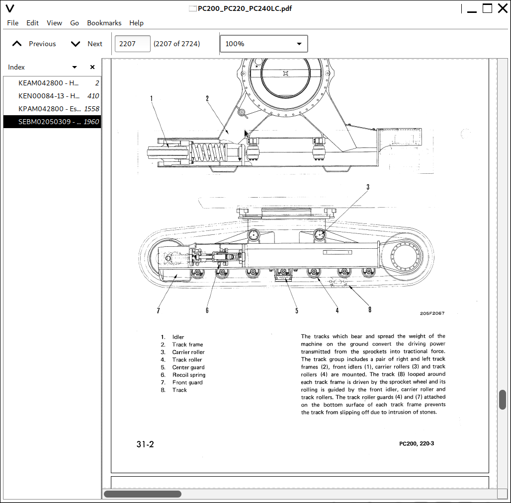
Track frame and recoil spring...92
Idler...94
Carrier roller...96
Track roller...97
Track shoe...98
Hydraulic system, Part 1...105
Hydraulic system, Part 1...106
Hydraulic equipment layout drawing...106
Hydraulic tank and filter...108
Hydraulic pump...110
Pilot oil filter...132
Hydraulic system, Part 2...135
Hydraulic system, Part 2...136
Control valve...136
CLSS...149
Functions and operation by valve...154
Hydraulic system, Part 3...193
Hydraulic system, Part 3...195
Swing motor...195
Center swivel joint...204
Travel motor...206
PPC valve...217
Work equipment and swing PPC valve...217
Travel PPC valve...223
Service PPC valve (with EPC valve)...232
Service PPC valve...238
Valve control...240
Solenoid valve...242
PPC accumulator...244
Return oil filter...245
Attachment circuit selector valve...246
Hydraulic cylinder...248
Work equipment...253
Work equipment...254
Dimensions of arm...265
Dimensions of bucket...267
Cab and its attachments...271
Cab and its attachments...272
Air conditioner piping...272
Electrical system...275
Electrical system...276
Engine control...276
Electrical control system...284
Monitor system...307
Sensor...334
KOMTRAX system...337
20 Standard value table...341
Standard service value table...341
Standard value table for engine related parts...342
Standard value table for chassis related parts...344
30 Testing and adjusting...363
Testing and adjusting, Part 1...363
Tools for testing, adjusting, and troubleshooting...365
Sketch of special tool...368
Testing engine speed...369
Testing intake air pressure (boost pressure)...370
Testing exhaust gas color...371
Adjusting valve clearance...372
Testing compression pressure...374
Testing blow-by pressure...375
Testing engine oil pressure...376
Handling fuel system parts...377
Releasing residual pressure from fuel system...377
Testing fuel pressure...378
Testing fuel delivery, return and leak amount...381
Bleeding air from fuel circuit...384
Checking fuel circuit for leakage...385
Checking and adjusting air conditioner compressor belt tension...386
Replacing fan belt...387
Testing swing circle bearing clearance...388
Checking and adjusting track shoe tension...389
Inspection and adjustment oil pressure in work equipment, swing, and travel circuits...391
Testing control circuit source pressure...394
Testing and adjusting oil pressure in pump PC control circuit...395
Testing and adjusting oil pressure in pump LS control circuit...398
Testing solenoid valve output pressure...403
Testing PPC valve output pressure...406
Adjusting play of work equipment and swing PPC valves...408
Checking parts which cause hydraulic drift of work equipment...409
Releasing residual pressure from hydraulic circuit...411
Testing oil leakage...412
Bleeding air from each part...415
Checking cab tipping stopper...417
Adjusting mirrors...418
Installation and adjustment of mirrors...419
Angle adjustment of rear view camera...425
Testing and adjusting, Part 2...429
Special functions of machine monitor...430
Testing and adjusting, Part 3...487
Handling voltage circuit of engine controller...488
Preparation work for troubleshooting of electrical system...489
Procedure for testing diodes...494
Pm Clinic service...495
40 Troubleshooting...505
Failure code table and fuse locations...505
Failure codes table...506
Fuse locations...511
General information on troubleshooting...517
Points to remember when troubleshooting...518
Sequence of events in troubleshooting...519
Check before troubleshooting...520
Classification and procedures for troubleshooting...521
How to read electric wire code...525
Connection table for connector pin numbers...528
T- branch box and T- branch adapter table...564
Troubleshooting by failure code (Display of code), Part 1...569
Failure code [989L00] Engine Controller Lock Caution 1...572
Failure code [989M00] Engine Controller Lock Caution 2...572
Failure code [989N00] Engine Controller Lock Caution 3...573
Failure code [AA10NX] Air Cleaner Clogging...573
Failure code [AB00KE] Charge Voltage Low...574
Failure code [B@BAZG] Eng Oil Press. Low...576
Failure code [B@BAZK] Eng Oil Level Low...576
Failure code [B@BCNS] Eng Water Overheat...577
Failure code [B@BCZK] Eng Water Level Low...577
Failure code [B@HANS] Hydr Oil Overheat...578
Failure code [CA111] EMC Critical Internal Failure...578
Failure code [CA115] Eng Ne and Bkup Speed Sens Error...579
Failure code [CA122] Chg Air Press Sensor High Error...580
Failure code [CA123] Chg Air Press Sensor Low Error...582
Failure code [CA131] Throttle Sensor High Error...584
Failure code [CA132] Throttle Sensor Low Error...586
Failure code [CA144] Coolant Temp Sens High Error...588
Failure code [CA145] Coolant Temp Sens Low Error...590
Failure code [CA153] Chg Air Temp Sensor High Error...592
Failure code [CA154] Chg Air Temp Sensor Low Error...594
Failure code [CA155] Chg Air Temp High Speed Derate...596
Failure code [CA187] Sens Supply 2 Volt Low Error...598
Failure code [CA221] Ambient Press Sens High Error...600
Failure code [CA222] Ambient Press Sens Low Error...602
Failure code [CA227] Sens Supply 2 Volt High Error...604
Failure code [CA234] Eng Overspeed...605
Failure code [CA238] Ne Speed Sens Supply Volt Error...606
Failure code [CA271] IMV/PCV1 Short Error...607
Failure code [CA272] IMV/PCV1 Open Error...608
Failure code [CA322] Inj #1 Open/Short Error...610
Failure code [CA323] Inj #5 Open/Short Error...612
Failure code [CA324] Inj #3 Open/Short Error...614
Failure code [CA325] Inj #6 Open/Short Error...616
Failure code [CA331] Inj #2 Open/Short Error...618
Failure code [CA332] Inj #4 Open/Short Error...620
Troubleshooting by failure code (Display of code), Part 2...623
Failure code [CA342] Calibration Code Incompatibility...625
Failure code [CA351] Injectors Drive Circuit Error...626
Failure code [CA352] Sens Supply 1 Volt Low Error...628
Failure code [CA386] Sens Supply 1 Volt High Error...630
Failure code [CA428] Water in Fuel Sensor High Error...632
Failure code [CA429] Water in Fuel Sensor Low Error...634
Failure code [CA435] Eng Oil Press Sw Error...636
Failure code [CA441] Battery Voltage Low Error...637
Failure code [CA442] Battery Voltage High Error...640
Failure code [CA449] Rail Press Very High Error...642
Failure code [CA451] Rail Press Sensor High Error...644
Failure code [CA452] Rail Press Sensor Low Error...646
Failure code [CA488] Chg Air Temp High Torque Derate...648
Failure code [CA553] Rail Press High Error...649
Failure code [CA559] Rail Press Low Error...650
Failure code [CA689] Eng Ne Speed Sensor Error...652
Failure code [CA731] Eng Bkup Speed Sens Phase Error...654
Failure code [CA757] All Continuous Data Lost Error...656
Failure code [CA778] Eng Bkup Speed Sensor Error...658
Failure code [CA1633] KOMNET Datalink Timeout Error...660
Failure code [CA2185] Throt Sens Sup Volt High Error...661
Failure code [CA2186] Throt Sens Sup Volt Low Error...662
Failure code [CA2249] Rail Press Very Low Error...663
Failure code [CA2311] IMV Solenoid Error...664
Failure code [CA2555] Grid Htr Relay Volt High Error...666
Failure code [CA2556] Grid Htr Relay Volt Low Error...668
Failure code [D19JKZ] Personal Code Relay Abnormality...670
Failure code [D862KA] GPS Antenna Discon...672
Failure code [DA22KK] Pump Solenoid Power Low Error...673
Failure code [DA25KP] 5V Sensor 1 Power Abnormality...675
Failure code [DA29KQ] Model Selection Abnormality...682
Troubleshooting by failure code (Display of code), Part 3...687
Failure code [DA2RMC] CAN Discon (Pump Con Detected)...690
Failure code [DAF8KB] Short circuit in camera power supply...696
![]()