
Komatsu Hydraulic Excavators PC78UU, PC78US, PC78US Repair Service Manual + Operation Maintenance Manual
Complete service repair manual with Electrical Wiring Diagrams for Komatsu Hydraulic Excavators PC78UU-6, PC78US-6, PC78US-8, with all the technical information to maintain, diagnose, repair, rebuild like professional mechanics.
Komatsu Hydraulic Excavators PC78UU-6, PC78US-6, PC78US-8 workshop service repair manual includes:
* Numbered table of contents easy to use so that you can find the information you need fast.
* Detailed sub-steps expand on repair procedure information
* Numbered instructions guide you through every repair procedure step by step.
* Troubleshooting and electrical service procedures are combined with detailed wiring diagrams for ease of use.
* Notes, cautions and warnings throughout each chapter pinpoint critical information.
* Bold figure number help you quickly match illustrations with instructions.
* Detailed illustrations, drawings and photos guide you through every procedure.
* Enlarged inset helps you identify and examine parts in detail.
PRODUCT DETAILS:
Total Pages: 4,842 pages
File Format: PDF (Internal Links, Bookmarked, Table of Contents, Searchable, Printable, high quality)
Language: English
SEBM025118 - Hydraulic Excavator PC78UU-6, PC78US-6 Shop Manual.pdf
SEN04543-10 - Hydraulic Excavator PC78US-8 Shop Manual.pdf
SEAM044600T - Hydraulic Excavator PC78US-6 Operation & Maintenance Manual.pdf
SEAM044601 - Hydraulic Excavator PC78US-6 Operation & Maintenance Manual.pdf
SEAM044602T - Hydraulic Excavator PC78US-6 Operation & Maintenance Manual.pdf
SEAM046100T - Hydraulic Excavator PC78US-5 Operation & Maintenance Manual.pdf
TEN00004-00 - Hydraulic Excavator GALEO PC78US-6 Operation & Maintenance Manual.pdf
TEN00072-01 - Hydraulic Excavator GALEO PC78US-6 Operation & Maintenance Manual.pdf
TEN00200-00 - Hydraulic Excavator GALEO PC78US-6 Operation & Maintenance Manual.pdf
TEN00307-05 - Hydraulic Excavator PC78US-8 Operation & Maintenance Manual.pdf
TEN00466-01 - Hydraulic Excavator PC78US-8 Operation & Maintenance Manual.pdf
MAIN SECTIONS
COVER...1
00 Index and foreword...0
100 Index...3
Composition of shop manual...4
Table of contents...6
200 Foreword and general information...15
Safety notice...16
How to read the shop manual...21
Explanation of terms for maintenance standard...23
Handling of electric equipment and hydraulic component...25
Handling of connectors newly used for engines...34
How to read electric wire code...37
Precautions when carrying out operation...40
Method of disassembling and connecting push-pull type coupler...43
Standard tightening torque table...46
Conversion table...50
01 Specification...0
100 Specification and technical data...57
Specification dimension drawing...58
Working range diagram...59
Specifications...60
Weight table...64
Table of fuel, coolant and lubricants...66
10 Structure, function and maintenance standard...0
100 Engine and cooling system...69
Engine mount...70
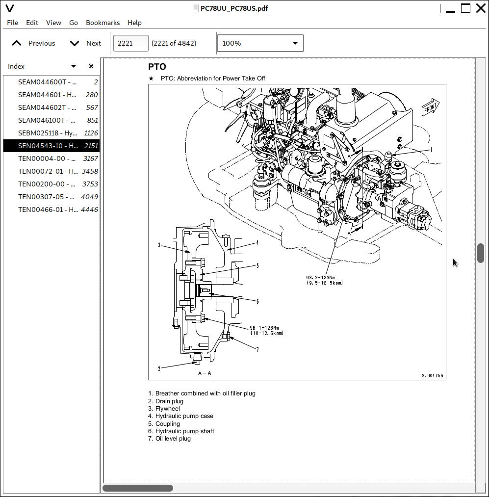
PTO...71
Cooling system...72
200 Power train...75
Power train...77
Swing circle...78
Swing machinery...80
300 Undercarriage and frame...83
Track frame...84
Idler cushion...85
Idler...86
Track roller...87
Carrier roller...88
Sprocket...89
Track shoe...90
401 Hydraulic system, Part 1...97
Hydraulic component layout drawing...98
Valve control...100
Hydraulic tank and filter...102
Hydraulic pump...104
402 Hydraulic system, Part 2...123
Control valve...124
CLSS...136
Functions and operation by valve...140
403 Hydraulic system, Part 3...173
PPC valve...175
Swing motor...191
Travel motor...202
Center swivel joint...210
Solenoid valve...212
PPC accumulator...215
Anti-drop valve...217
Multi-control valve...222
500 Work equipment...225
Work equipment...226
Dimensions of components...228
Work equipment cylinder...234
600 Cab and its attachments...237
Air conditioner...238
700 Electrical system...251
Electronic control system...252
Monitor system...284
KOMTRAX system...298
Sensor...300
20 Standard value table...0
100 Standard service value table...307
Standard value table for engine related parts...308
Standard value table for chassis...309
30 Testing and adjusting...0
101 Testing and adjusting, Part 1...319
Tools for testing, adjusting, and troubleshooting...321
Testing engine speed...326
Testing exhaust temperature...327
Checking exhaust gas color...328
Adjusting valve clearance...329
Testing compression pressure...331
Testing blow-by pressure...333
Testing engine oil pressure...334
Handling fuel system parts...335
Releasing residual pressure from fuel system...335
Testing fuel pressure...336
Testing fuel return rate and fuel leakage...337
Bleeding air from fuel circuit...339
Checking fuel circuit for leakage...341
Testing and adjusting alternator belt tension...342
Checking and adjusting air conditioner compressor belt tension...344
Testing swing circle bearing clearance...345
Checking and adjusting track shoe tension...346
Testing and adjusting oil pressure in work equipment and travel circuits...348
Testing and adjusting swing and blade circuit oil pressure (Blade specification)...350
Testing control circuit basic pressure...353
Testing and adjusting oil pressure in pump PC control circuit...354
Testing PC-EPC solenoid output pressure...357
Testing LS differential pressure and adjusting LS valve...358
Testing solenoid valve output pressure...360
Testing PPC valve output pressure...362
Adjusting play of work equipment and swing PPC valves...364
Checking parts which cause hydraulic drift of work equipment...365
Testing and adjusting travel deviation...367
Releasing residual pressure from hydraulic circuit...369
Testing oil leakage...370
Bleeding air from each part...373
Adjusting mirrors...375
Testing and adjusting hood catch...376
102 Testing and adjusting, Part 2...379
Special functions of machine monitor...380
103 Testing and adjusting, Part 3...431
Handling voltage circuit of engine controller...432
Preparation work for troubleshooting of electrical system...433
Procedure for testing diodes...438
Pm Clinic service...439
40 Troubleshooting...0
100 Failure code table and fuse locations...445
Failure code table...446
Fuse locations...448
200 General information on troubleshooting...453
Points to remember when troubleshooting...454
Sequence of events in troubleshooting...455
Checks before troubleshooting...456
Classification and troubleshooting steps...457
Information in troubleshooting table...458
Phenomena looking like troubles and troubleshooting Nos...460
Connection table for connector pin numbers...463
T- branch box and T- branch adapter table...499
301 Troubleshooting by failure code, Part 1...503
Failure code [989L00] Engine controller lock caution 1...505
Failure code [989M00] Engine controller lock caution 2...506
Failure code [989N00] Engine controller lock caution 3...507
Failure code [AB00KE] Charge voltage low...508
Failure code [B@BAZG] Eng oil press. low...510
Failure code [B@BCNS] Eng coolant overheat...511
Failure code [B@HANS] Hydr oil overheat...511
Failure code [CA111] ECM critical internal failure...512
Failure code [CA115] Eng. Ne and Bkup speed sensor error...515
Failure code [CA122] Charge air press sensor high error...516
Failure code [CA123] Charge air press sensor low error...518
Failure code [CA131] Throttle sensor high error...520
Failure code [CA132] Throttle sensor low error...522
Failure code [CA144] Coolant temp. sensor high error...524
Failure code [CA145] Coolant temp. sensor low error...526
Failure code [CA153] Charge air temp. sensor high error...528
Failure code [CA154] Charge air temp. sensor low error...530
Failure code [CA187] Sensor sup. 2 volt. low error...531
Failure code [CA221] Ambient air press. sensor high error...532
Failure code [CA222] Ambient air press. sensor low error...534
Failure code [CA227] Sensor sup. 2 volt. high error...535
Failure code [CA234] Eng. overspeed...536
Failure code [CA238] Ne speed sensor sup. volt. error...538
Failure code [CA271] IMV/PCV1 short error...540
Failure code [CA272] IMV/PCV1 open error...541
Failure code [CA322] Injector #1 (L #1) system open/short error...542
Failure code [CA324] Injector #3 (L #3) system open/short error...544
Failure code [CA331] Injector #2 (L #2) system open/short error...546
Failure code [CA332] Injector #4 (L #4) system open/short error...548
302 Troubleshooting by failure code, Part 2...551
Failure code [CA351] Inj. drive circuit error...553
Failure code [CA352] Sensor sup. 1 volt. low error...556
Failure code [CA386] Sensor sup. 1 volt. high error...558
Failure code [CA435] Abnormality in engine oil pressure switch...560
Failure code [CA441] Battery voltage low error...561
Failure code [CA442] Battery voltage high error...562
Failure code [CA449] Rail press. very high error...563
Failure code [CA451] Rail press. sensor high error...564
Failure code [CA452] Rail press. sensor low error...566
Failure code [CA488] Chg air temp high torque derate...567
Failure code [CA553] Rail press. high error...568
Failure code [CA559] Rail press. low error...569
Failure code [CA689] Eng. Ne speed sensor error...572
Failure code [CA731] Eng. Bkup speed sensor phase error...574
Failure code [CA757] All persistent data lost error...575
Failure code [CA778] Eng. Bkup speed sensor error...576
Failure code [CA1633] KOMNET datalink timeout error...578
Failure code [CA2185] Throttle sens. sup. volt. high error...580
Failure code [CA2186] Throttle sens. sup. volt. low error...582
Failure code [CA2249] Rail press. very low error...582
Failure code [CA2311] Abnormality in IMV solenoid...583
Failure code [D110KB] Battery relay drive short...584
Failure code [D19JKZ] Personal code relay abnormality...586
Failure code [D862KA] GPS antenna discon...588
Failure code [DA22KK] Pump solenoid power low error...590
Failure code [DA25KP] 5V sensor 1 power abnormality...592
Failure code [DA26KP] 5V sensor 2 power abnormality...594
Failure code [DA29KQ] Model selection abnormality...596
303 Troubleshooting by failure code, Part 3...599
Failure code [DA2RMC] CAN discon (Pump controller detected)...600
Failure code [DAFGMC] GPS module error...602
Failure code [DAFRMC] CAN discon (Monitor detected)...604
Failure code [DGH2KB] Hydr oil sensor short...606
Failure code [DHPAMA] Pump press sensor abnormality...608
Failure code [DHS5KX] Travel PPC press sensor abnormality...610
COVER...1
FOREWORD...2
FOREWORD...3
SAFETY INFORMATION...6
INTRODUCTION...8
DIRECTIONS OF MACHINE...8
PRODUCT INFORMATION...9
PRODUCT IDENTIFICATION NUMBER (PIN)/MACHINE SERIAL NO. PLATE...9
ENGINE SERIAL NUMBER PLATE AND ITS LOCATION...9
EPA NAMEPLATE...10
SERVICE METER LOCATION...10
YOUR MACHINE SERIAL NUMBERS AND DISTRIBUTOR...11
CONTENTS...12
SAFETY...16
SAFETY INFORMATION...17
SAFETY LABELS...19
LOCATION OF SAFETY LABELS...20
SAFETY LABELS...21
SAFETY INFORMATION...27
SAFETY RULES...27
IF PROBLEMS ARE FOUND...27
WORKING WEAR AND PERSONAL PROTECTIVE ITEMS...27
FIRE EXTINGUISHER AND FIRST AID KIT...27
SAFETY EQUIPMENT...27
KEEP MACHINE CLEAN...28
KEEP OPERATOR'S COMPARTMENT CLEAN...28
LEAVING OPERATOR'S SEAT WITH LOCK...28
HANDRAILS AND STEPS...29
MOUNTING AND DISMOUNTING...29
NO PERSONS ON ATTACHMENTS...29
DO NOT GET CAUGHT IN ARTICULATED PORTION...29
BURN PREVENTION...30
![]()