
Komatsu Hydraulic Excavators PC18MR, PC18MR Repair Service Manual
Complete service repair manual with Electrical Wiring Diagrams for Komatsu Hydraulic Excavators PC18MR-2, PC18MR-3, with all the technical information to maintain, diagnose, repair, rebuild like professional mechanics.
Komatsu Hydraulic Excavators PC18MR-2, PC18MR-3 workshop service repair manual includes:
* Numbered table of contents easy to use so that you can find the information you need fast.
* Detailed sub-steps expand on repair procedure information
* Numbered instructions guide you through every repair procedure step by step.
* Troubleshooting and electrical service procedures are combined with detailed wiring diagrams for ease of use.
* Notes, cautions and warnings throughout each chapter pinpoint critical information.
* Bold figure number help you quickly match illustrations with instructions.
* Detailed illustrations, drawings and photos guide you through every procedure.
* Enlarged inset helps you identify and examine parts in detail.
PRODUCT DETAILS:
Total Pages: 1,865 pages
File Format: PDF (Internal Links, Bookmarked, Table of Contents, Searchable, Printable, high quality)
Language: English
SEBM038404 - Hydraulic Excavator PC18MR-2 Shop Manual.pdf
SEN04306-04 - Hydraulic Excavator PC18MR-3 Shop Manual.pdf
TEN00052-01 - Hydraulic Excavator GALEO PC18MR-2 Operation & Maintenance Manual.pdf
TEN00292-03 - Hydraulic Excavator PC18MR-3 Operation & Maintenance Manual.pdf
TEN00514-01 - Hydraulic Excavator PC18MR-3 Operation & Maintenance Manual.pdf
TEN00549-00 - Hydraulic Excavator PC18MR-3 Operation & Maintenance Manual.pdf
MAIN SECTIONS
COVER...1
00 Index and foreword...0
100 Index...2
Composition of shop manual...3
Table of contents...5
200 Foreword and general information...10
Safety notice...11
How to read the shop manual...16
Explanation of terms for maintenance standard...18
Handling of electric equipment and hydraulic component...20
Handling of connectors newly used for engines...29
How to read electric wire code...32
Precautions when carrying out operation...35
Method of disassembling and connecting push-pull type coupler...38
Standard tightening torque table...41
Conversion table...45
01 Specification...0
100 Specification and technical data...52
Specification dimension drawing...53
Working range drawing...54
Specifications...55
Weight table...58
Table of fuel, coolant and lubricants...60
10 Structure, function and maintenance standard...0
100 Engine and cooling system...62
PTO...63
Cooling system...65
200 Power train...68
Power train...69
Swing circle...70
300 Undercarriage and frame...72
Track frame...73
Idler cushion...74
Idler...76
Track roller...77
Sprocket...78
Track shoe...79
410 Hydraulic system, Part 1...82
Hydraulic components layout drawing...83
Hydraulic tank...84
Center swivel joint...85
Travel motor...86
Hydraulic cylinder...95
Solenoid valve...99
Variable gauge valve...102
Multi-control valve (If equipped)...103
420 Hydraulic system, Part 2...106
Hydraulic pump...107
Control valve...113
430 Hydraulic system, Part 3...124
CLSS...125
Operation for each function and valve...129
Swing motor...143
PPC valve...146
500 Work equipment...156
Work equipment...158
Dimensions of each part of work equipment...161
600 Cab and its attachments...166
Floor...167
700 Electrical system...170
Engine control system...171
Electric control system...173
Component parts of system...178
KOMTRAX system...179
Monitor system...182
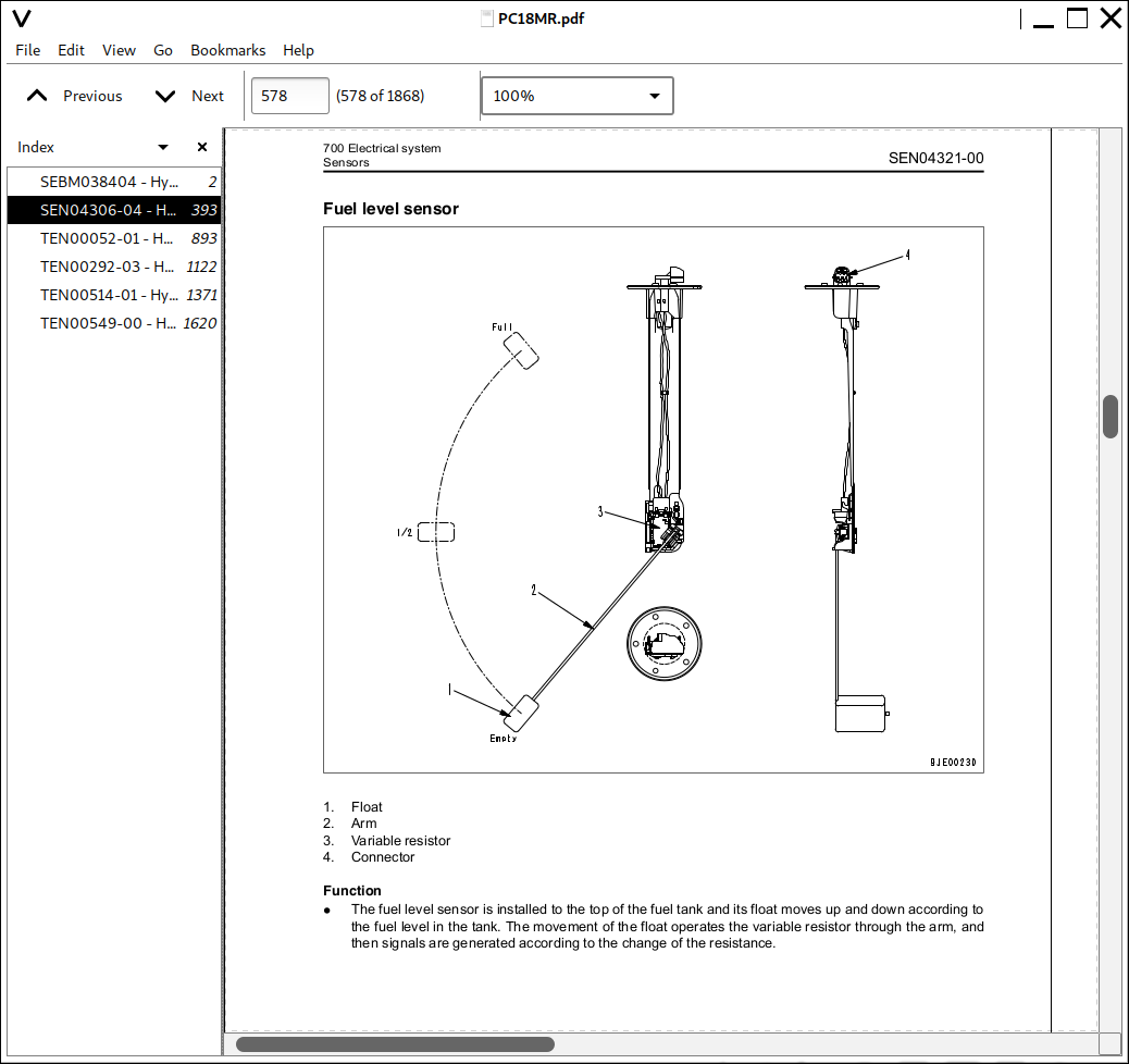
Sensors...185
20 Standard value table...0
100 Standard service value table...188
Standard value table for engine related parts...189
Standard value table for chassis related parts...190
30 Testing and adjusting...0
100 Testing and adjusting...200
List of testing, adjusting, and troubleshooting tools...202
Measuring engine speed...204
Measurement of exhaust gas color...205
Adjusting valve clearance...206
Testing compression pressure...208
Testing engine oil pressure...209
Testing and adjusting fuel injection timing...210
Adjusting engine stop solenoid...212
Bleeding air from fuel circuit...213
Testing and adjusting fan belt tension...214
Adjusting fuel control lever linkage...215
Measurement of clearance in swing circle bearings...216
Testing and adjusting track shoe tension...217
Testing and adjusting oil pressures in work equipment, travel, swing, and blade circuits...219
Testing and adjusting control circuit basic pressure...222
Testing and adjusting pump LS differential pressure...224
Measuring solenoid valve output pressure...226
Measuring PPC valve output pressure...228
Adjusting play of work equipment and swing PPC valves...230
Measuring swing holding brake release pressure...230
Testing oil leakage from cylinder...232
Releasing residual pressure from hydraulic circuit...234
Bleeding air from cylinder...234
Pressurizing hydraulic tank...235
How to open and close (tilt) floor...236
Inspection procedures for diode...238
How to start operation of KOMTRAX terminal...239
Lamp display of KOMTRAX terminal...243
Removal and installation of KOMTRAX terminal...246
Preparation work for troubleshooting of electrical system...247
40 Troubleshooting...0
100 General information on troubleshooting...250
Points to remember when troubleshooting...251
Sequence of events in troubleshooting...252
Checks before troubleshooting...253
Classification and procedures of troubleshooting...254
Connection table for connector pin numbers...257
T- branch box and T- branch adapter table...293
200 Troubleshooting of electrical system (E-mode)...298
Before carrying out troubleshooting for electrical system (E-mode)...299
Information contained in troubleshooting table...301
E-1 Engine does not start...302
E-2 Engine does not stop...309
E-3 When starting switch is turned ON, any item does not operate...311
E-4 When starting switch is turned ON, some items do not operate...313
E-5 Alarm buzzer is abnormal...314
E-6 Engine oil pressure caution is turned ON...316
E-7 Charge level caution is turned ON...317
E-8 Preheating system does not operate or preheater does not become hot...319
E-9 Coolant temperature gauge is abnormal...321
E-10 Fuel level gauge is abnormal...325
E-11 Service meter does not operate while engine is running...329
E-12 2nd travel speed is not selected...332
E-13 Working lamp does not light up...335
E-14 When work equipment lock (PPC basic pressure lock) lever is set in LOCK, work equipment still moves...337
E-15 Blade/Variable gauge selector system does not operate normally...340
300 Troubleshooting of hydraulic and mechanical system (H-mode)...344
Information contained in troubleshooting table...346
H-1 Speed or power of whole work equipment, travel, swing, and blade is low...347
H-2 Engine speed lowers extremely or engine stalls...348
H-3 Whole work equipment, travel system, swing system, and blade do not move...349
H-4 Abnormal sound comes out from around hydraulic pump...350
H-5 Fine control performance or response is low...350
H-6 Speed or power of boom is low...351
H-7 Speed or power of arm is low...352
H-8 Speed or power of bucket is low...353
H-9 Speed or power of boom swing is low...354
H-10 Work equipment does not move singly...354
H-11 Work equipment hydraulic drift is large...355
H-12 Time lag of work equipment is large...356
H-13 In compound operation of work equipment, speed of part loaded more is low...356
H-14 Machine deviates during travel...357
H-15 Travel speed or travel power is low...359
H-16 Machine is not steered well or steering power is low...359
H-17 Travel speed does not change...360
H-18 Travel motor does not work (one side only)...360
H-19 Speed or power of swing is low...361
H-20 Machine does not swing...363
H-21 Swing acceleration performance is low...365
H-22 Machine overruns when it stops swinging...366
H-23 Large shock is made when machine stops swinging...367
H-24 When upper structure stops swinging, it makes large sound...367
H-25 Hydraulic drift of swing is large...368
H-26 Speed or power of blade is low...369
H-27 Blade does not move...370
H-28 Hydraulic drift of blade is large...370
H-29 Variable gauge does not move...371
H-30 Troubleshooting for hydraulic breaker...372
400 Troubleshooting of engine (S-mode)...376
Troubleshooting chart...377
50 Disassembly and assembly...0
100 General information on disassembly and assembly...382
How to read this manual...383
Coating materials list...385
Special tool list...388
Sketches of special tools...390
200 Engine and cooling system...394
Removal and installation of fuel injection pump assembly...395
Removal and installation of radiator assembly...396
Removal and installation of hydraulic oil cooler assembly...398
Removal and installation of engine and hydraulic pump assembly...399
300 Power train...406
Removal and installation of swing circle assembly...407
400 Undercarriage and frame...410
Removal and installation of track shoe assembly...411
Disassembly and assembly of idler assembly...412
Disassembly and assembly of recoil spring...414
Disassembly and assembly of track roller assembly...416
Assembly of travel motor assembly...418
Removal and installation of floor frame assembly...427
Removal and installation of revolving frame...431
500 Hydraulic system...436
Disassembly and assembly of hydraulic pump assembly...437
Disassembly and assembly of control valve assembly...447
Removal and installation of hydraulic system and center swivel joint assembly...453
Disassembly and assembly of center swivel joint assembly...455
Removal and installation of swing motor assembly...457
Disassembly and assembly of swing motor assembly...458
Disassembly and assembly of hydraulic cylinder assembly...465
Disassembly and assembly of hydraulic breaker assembly...469
600 Work equipment...478
Removal and installation of work equipment assembly...479
700 Cab and its attachments...482
Removal and installation of canopy...483
800 Electrical system...486
Removal and installation of KOMTRAX terminal...487
90 Diagrams and drawings...0
100 Hydraulic diagrams and drawings...490
Hydraulic circuit diagram...492
200 Electrical diagrams and drawings...495
Electrical circuit diagram...497
Connector list and stereogram...498
MAIN MENU...0
COVER...1
FOREWORD...2
FOREWORD...3
SAFETY INFORMATION...6
INTRODUCTION...8
DIRECTIONS OF MACHINE...8
PRODUCT INFORMATION...9
PRODUCT IDENTIFICATION NUMBER (PIN)/MACHINE SERIAL NO. PLATE...9
ENGINE SERIAL NUMBER PLATE AND ITS LOCATION...9
EPA NAMEPLATE...10
SERVICE METER LOCATION...10
YOUR MACHINE SERIAL NUMBERS AND DISTRIBUTOR...11
CONTENTS...12
SAFETY...16
SAFETY INFORMATION...17
SAFETY LABELS...19
LOCATION OF SAFETY LABELS...19
SAFETY LABELS...20
SAFETY INFORMATION...25
SAFETY MACHINE OPERATION...34
STARTING ENGINE...34
OPERATION...36
TRANSPORTATION...42
BATTERY...43
TOWING...45
LIFTING OBJECTS WITH BUCKET...46
SAFETY MAINTENANCE INFORMATION...47
OPERATION...54
MACHINE VIEW ILLUSTRATIONS...55
OVERALL MACHINE VIEW...55
CONTROLS AND GAUGES...56
DETAILED CONTROLS AND GAUGES...57
MONITORING SYSTEM...57
SWITCHES...63
CONTROL LEVERS AND PEDALS...67
COVER WITH LOCK...72
ENGINE REAR COVER...73
COOLING COVER...74
BATTERY COVER...75
METHOD OF OPENING (TILTING) FLOOR...76
FUSE...80
BLOCK FUSE...80
OPERATION MANUAL STORAGE...81
TOOL BOX...81
MACHINE OPERATIONS AND CONTROLS...82
BEFORE STARTING ENGINE...82
STARTING ENGINE...95
AFTER STARTING ENGINE...99
STOPPING THE ENGINE...102
MACHINE OPERATION...103
STEERING THE MACHINE...108
SWINGING...110
WORK EQUIPMENT CONTROLS AND OPERATIONS...111
PROHIBITED OPERATIONS...114
GENERAL OPERATION INFORMATION...116
TRAVELING ON SLOPES...118
ESCAPE FROM MUD...120
WORK POSSIBLE USING COMPACT HYDRAULIC EXCAVATOR...121
BUCKET REPLACEMENT...123
PARKING MACHINE...124
MACHINE INSPECTION AFTER DAILY WORK...125
LOCKING...126
RUBBER SHOES (MACHINE WITH RUBBER SHOES ONLY)...127
TRANSPORTATION...132
TRANSPORTATION PROCEDURE...132
LOADING AND UNLOADING WITH TRAILER...132
LIFTING MACHINE...138
COLD WEATHER OPERATION...141
COLD WEATHER OPERATION INFORMATION...141
AFTER DAILY WORK COMPLETION...143
AFTER COLD WEATHER SEASON...143
LONG TERM STORAGE...144
BEFORE STORAGE...144
DURING STORAGE...144
AFTER STORAGE...144
TROUBLES AND ACTIONS...145
RUNNING OUT OF FUEL...145
PHENOMENA THAT ARE NOT FAILURES...145
TOWING THE MACHINE...146
SEVERE JOB CONDITION...146
DISCHARGED BATTERY...147
OTHER TROUBLE...151
MAINTENANCE...154
MAINTENANCE INFORMATION...155
OUTLINE OF SERVICE...157
HANDLING OIL, FUEL, COOLANT, AND PERFORMING OIL CLINIC...157
ELECTRIC SYSTEM MAINTENANCE...160
HANDLING HYDRAULIC SYSTEM...160
WEAR PARTS...161
WEAR PARTS LIST...161
RECOMMENDED FUEL, COOLANT, AND LUBRICANT...162
RECOMMENDED BRANDS, RECOMMENDED QUALITY FOR PRODUCTS OTHER THAN KOMATSU GENUINE OIL...164
TIGHTENING TORQUE SPECIFICATIONS...165
TIGHTENING TORQUE LIST...165
SAFETY CRITICAL PARTS...166
SAFETY CRITICAL PARTS LIST...166
MAINTENANCE SCHEDULE...167
MAINTENANCE SCHEDULE CHART...167
MAINTENANCE INTERVAL FOR HYDRAULIC BREAKER...168
MAINTENANCE PROCEDURE...169
WHEN REQUIRED...169
CHECK BEFORE STARTING...191
EVERY 500 HOURS MAINTENANCE...192
EVERY 1000 HOURS MAINTENANCE...199
EVERY 2000 HOURS MAINTENANCE...202
SPECIFICATIONS...204
SPECIFICATIONS...205
ATTACHMENTS AND OPTIONS...208
ATTACHMENTS AND OPTIONS - GENERAL INFORMATION...209
SAFETY FIRST...209
ATTACHMENT INSTALLATION...210
BUCKET WITH HOOK...211
PROHIBITED OPERATIONS...211
MACHINE READY FOR ATTACHMENT...212
LOCATIONS...212
HYDRAULIC CIRCUIT...214
ATTACHMENT OPERATIONS...216
LONG TERM STORAGE...217
SPECIFICATIONS...217
CHANGING MACHINE CONTROL PATTERN (IF PATTERN CHANGE VALVE EQUIPPED)...218
CONTROL PATTERN CHANGE PROCEDURE...218
MACHINE CONTROL PATTERNS...219
ATTACHMENT GUIDE...220
ATTACHMENT COMBINATIONS...220
RECOMMENDED ATTACHMENT OPERATIONS...221
HYDRAULIC BREAKER...221
INDEX...226
![]()