
Komatsu Hydraulic Excavator PC45MR, PC55MR Repair Service Manual + Operation Maintenance Manual
Complete service repair manual with Electrical Wiring Diagrams for Komatsu Hydraulic Excavator PC45MR-3, PC55MR-3, with all the technical information to maintain, diagnose, repair, rebuild like professional mechanics.
Komatsu Hydraulic Excavator PC45MR-3, PC55MR-3 workshop service repair manual includes:
* Numbered table of contents easy to use so that you can find the information you need fast.
* Detailed sub-steps expand on repair procedure information
* Numbered instructions guide you through every repair procedure step by step.
* Troubleshooting and electrical service procedures are combined with detailed wiring diagrams for ease of use.
* Notes, cautions and warnings throughout each chapter pinpoint critical information.
* Bold figure number help you quickly match illustrations with instructions.
* Detailed illustrations, drawings and photos guide you through every procedure.
* Enlarged inset helps you identify and examine parts in detail.
PRODUCT DETAILS:
Total Pages: 1,576 pages
File Format: PDF (Internal Links, Bookmarked, Table of Contents, Searchable, Printable, high quality)
Language: English
SEN04597-06 - Hydraulic Excavator PC45MR-3, PC55MR-3 Shop Manual.pdf
TEN00306-03 - Hydraulic Excavator PC45MR-3, PC55MR-3 Operation & Maintenance Manual.pdf
TEN00390-03 - Hydraulic Excavator PC45MR-3, PC55MR-3 Operation & Maintenance Manual.pdf
TEN00508-01 - Hydraulic Excavator PC45MR-3, PC55MR-3 Operation & Maintenance Manual.pdf
MAIN SECTIONS
COVER...1
00 Index and foreword...0
100 Index...2
Composition of shop manual...3
Table of contents...5
200 Foreword and general information...12
Safety notice...13
How to read the shop manual...19
Explanation of terms for maintenance standard...21
Handling of electric equipment and hydraulic component...23
Handling of connectors newly used for engines...32
How to read electric wire code...35
Precautions when carrying out work...38
Method of disassembling and connecting push-pull type coupler...41
Standard tightening torque table...44
Conversion table...48
01 Specification...0
100 Specification and technical data...54
Specification dimension drawing...55
Working range drawing...56
Specifications...57
Weight table...63
Table of fuel, coolant and lubricants...67
10 Structure, function and maintenance standard...0
100 Engine and cooling system...70
PTO...71
Cooling system...73
200 Power train...76
Power train...77
Swing circle...78
Swing machinery...79
300 Undercarriage and frame...82
Track frame...83
Idler cushion...84
Idler...85
Track roller...87
Carrier roller...88
Sprocket...89
Track shoe...90
410 Hydraulic system, Part 1...94
Hydraulic components layout drawing...95
Hydraulic tank, filter...96
Center swivel joint...98
Travel motor...99
Hydraulic cylinder...107
Solenoid valve...111
Multi-control valve...116
420 Hydraulic system, Part 2...118
Hydraulic pump...119
Control valve...127
Anti-drop valve...141
430 Hydraulic system, Part 3...148
CLSS...149
Operation for each function and valve...153
Swing motor...175
PPC valve...182
500 Work equipment...196
Work equipment...197
Dimensions of each part of work equipment...201
600 Cab and its attachments...206
Floor...207
700 Electrical system...210
Engine control system...211
Electrical control system...215
Auto-deceleration function...221
Attachment proportional switch, breaker operation switch, work mode selection, flow control function...223
KOMTRAX system...231
Component parts of system...234
Monitor system...235
Sensors...238
20 Standard value table...0
100 Standard service value table...242
Standard service value table for engine related parts...243
Standard service value table for chassis related parts...245
30 Testing and adjusting...0
100 Testing and adjusting...262
Tools for testing, adjusting, and troubleshooting...264
Testing engine speed...267
Testing exhaust gas color...268
Testing and adjusting valve clearance...269
Testing compression pressure...271
Testing engine oil pressure...272
Testing and adjusting fuel injection timing...273
Testing and adjusting alternator belt tension...277
Testing and adjusting air conditioner compressor belt tension...278
Adjusting fuel control lever...279
Testing clearance in swing circle bearings...280
Testing and adjusting track shoe tension...281
Testing and adjusting oil pressures in work equipment, travel, boom swing, swing, and blade circuits...282
Testing and adjusting LS differential pressure...287
Adjusting PC valve...290
Testing and adjusting control pump circuit oil pressure...291
Testing solenoid valve output pressure...293
Testing PPC valve output pressure...294
Adjusting PPC valve...296
Testing swing holding brake release pressure...297
Testing and adjusting travel deviation...298
Testing oil leakage from work equipment cylinder...300
Bleeding air from each part...302
Releasing residual pressure from hydraulic circuit...304
Releasing residual pressure from hydraulic tank...305
Pressurizing hydraulic tank...305
How to open and close (tilt) floor...306
Inspection procedures for diode...311
Function and flow of operator and service mode...313
How to start operation of KOMTRAX terminal...337
Lamp display of KOMTRAX terminal...341
Removal and installation of KOMTRAX terminal...344
Preparation work for troubleshooting of electrical system...345
40 Troubleshooting...0
100 General information on troubleshooting...348
Points to remember when troubleshooting...349
Sequence of events in troubleshooting...350
Checks before troubleshooting...351
Classification and procedures of troubleshooting...352
Information contained in troubleshooting table...353
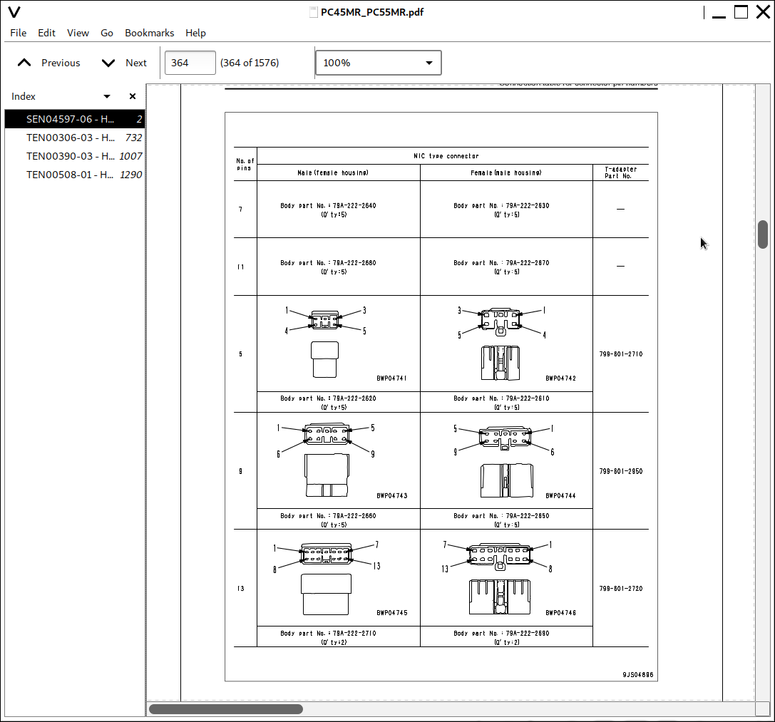
Connection table for connector pin numbers...357
T- branch box and T- branch adapter table...393
110 Failure code table and fuse locations...398
User code and failure code list...399
Fuse locations...400
120 General information on troubleshooting...404
Points to remember when troubleshooting...405
Sequence of events in troubleshooting...406
Checks before troubleshooting...407
Classification and procedures of troubleshooting...408
Information contained in troubleshooting table...409
Connection table for connector pin numbers...413
T- branch box and T- branch adapter table...449
130 Troubleshooting by failure code...454
Failure code [DBHRKR] Communication error between monitor panel and attachment switch controller...456
Failure code [DBH1KK] Unswitched power supply error...458
Failure code [DBH2KK] Solenoid power supply error...460
Failure code [DBH5KP] 5V sensor power supply output 0 error...462
Failure code [DBH6KP] 5V sensor power supply output 1 error...463
Failure code [DDWLKA] Breaker switch error (Disconnection or short circuit)...464
Failure code [DDWLKB] Breaker switch error (Hot short circuit)...465
Failure code [DFB1KA] Attachment switch (main) error (Disconnection or ground fault)...466
Failure code [DFB1KB] Attachment switch (main) error (Hot short circuit)...467
Failure code [DFB3L8] Attachment switch (main-sub) voltage difference error...468
Failure code [DK10KA] Fuel control dial potentiometer error (Disconnection or ground fault)...469
Failure code [DK10KB] Fuel control dial potentiometer error (Hot short circuit)...471
Failure code [DK58KA] Governor stroke sensor error (Disconnection or ground fault)...473
Failure code [DK58KB] Governor stroke sensor error (Hot short circuit)...475
Failure code [D1E0KZ] Motor power supply relay error (Disconnection or hot short circuit)...477
Failure code [D1E0KB] Motor power supply relay error (Ground fault)...479
Failure code [D1E1KZ] Motor drive relay (+) error (Disconnection or hot short circuit)...481
Failure code [D1E1KB] Motor drive relay (+) error (Ground fault)...483
Failure code [D1E2KZ] Motor drive relay (-) error (Disconnection or hot short circuit)...485
Failure code [D1E2KB] Motor drive relay (-) error (Ground fault)...487
Failure code [DY10MA] Fuel control motor operation error...489
Failure code [D1E0KA] Fuel control motor power supply relay contactsticking (NC side)...491
Failure code [D1E0KY] Fuel control motor power supply relay contact sticking (NO side)...493
Failure code [DXEAKA] EPC valve (port A side) error (Disconnection)...495
Failure code [DXEAKB] EPC valve (port B side) error (Ground fault)...497
Failure code [DXEAKY] EPC valve (port A side) error (Hot short circuit)...498
200 Troubleshooting of electrical system (E-mode)...500
Before carrying out troubleshooting of electrical system...501
E-1 Engine does not start...503
E-2 Engine does not stop...511
E-3 When starting switch is turned ON, any item does not operate...513
E-4 When starting switch is turned ON, some items do not operate...515
E-5 Alarm buzzer is abnormal...516
E-6 Engine oil pressure caution is turned ON...518
E-7 Charge level caution is turned ON...519
E-8 Preheating system does not operate or preheater does not become hot...521
E-9 Coolant temperature gauge is abnormal...523
E-10 Fuel level gauge is abnormal...527
E-11 Service meter does not operate while engine is running...531
E-12 2nd travel speed is not selected...534
E-13 Working lamp does not light up...537
E-14 When work equipment lock (PPC basic pressure lock) lever is set in LOCK, work equipment still moves...539
E-15 Windshield wiper does not operate...541
E-16 Windshield washer does not operate...543
E-17 Defective air conditioner...545
E-18 KOMTRAX system does not operate normally...553
300 Troubleshooting of hydraulic and mechanical system (H-mode)...556
Information contained in troubleshooting table...558
H-1 Speed or power of whole work equipment, travel, swing, and blade is low...559
H-2 Engine speed lowers extremely or engine stalls...563
H-3 Whole work equipment, travel system, swing system, and blade do not work...564
H-4 Abnormal sound comes out from around hydraulic pump...568
H-5 Fine control performance or response is low...568
H-6 Speed or power of boom is low...569
H-7 Speed or power of arm is low...570
H-8 Speed or power of bucket is low...571
H-9 Speed or power of boom swing is low...572
H-10 Work equipment does not move singly...572
H-11 Work equipment hydraulic drift is large...573
H-12 Time lag of work equipment is large...575
H-13 In compound operation of work equipment, speed of part loaded more is low...575
H-14 Machine deviates during travel...576
H-15 Travel speed or travel power is low (while work equipment is normal)...578
H-16 Machine is not steered well or steering power is low...579
H-17 Travel speed does not change...580
H-18 Travel motor does not work...581
H-19 Speed or power of swing is low...583
H-20 Machine does not swing...585
H-21 Swing acceleration performance is low...587
H-22 Machine overruns when it stops swinging...589
H-23 Large shock is made when machine stops swinging...590
H-24 When upper structure stops swinging, it makes large sound...590
H-25 Hydraulic drift of swing is large...591
H-26 Speed or power of blade is low...592
H-27 Blade does not move...593
H-28 Hydraulic drift of blade is large...594
400 Troubleshooting of engine (S-mode)...596
Method of using troubleshooting charts...598
S-1 Starting performance is poor...601
S-2 Engine does not start...602
S-3 Engine does not pick up smoothly...605
S-4 Engine stops during operations...606
S-5 Engine does not rotate smoothly...607
S-6 Engine lacks output (or lacks power)...608
S-7 Exhaust smoke is black (incomplete combustion)...609
S-8 Oil consumption is excessive (or exhaust smoke is blue)...610
S-9 Oil becomes contaminated quickly...611
S-10 Fuel consumption is excessive...612
S-11 Oil is in coolant (or coolant spurts back or coolant level goes down)...613
S-12 Oil pressure drops...614
S-13 Oil level rises (Entry of coolant/fuel)...615
S-14 Coolant temperature becomes too high (overheating)...616
S-15 Abnormal noise is made...617
S-16 Vibration is excessive...618
50 Disassembly and assembly...0
100 General information on disassembly and assembly...620
How to read this manual...621
Coating materials list...623
Special tool list...626
Sketches of special tools...629
200 Engine and cooling system...632
Removal and installation of fuel injection pump assembly...633
Removal and installation of radiator assembly...635
Removal and installation of hydraulic oil cooler assembly...637
Removal and installation of engine and hydraulic pump assembly...641
300 Power train...648
Removal and installation of swing motor and swing machinery assembly...649
Disassembly and assembly of swing motor and swing machinery assembly...650
Removal and installation of swing circle assembly...655
400 Undercarriage and frame...658
Removal and installation of track shoe assembly...659
Disassembly and assembly of idler assembly...660
Disassembly and assembly of recoil spring assembly...662
Disassembly and assembly of track roller assembly...665
Disassembly and assembly of carrier roller assembly...666
Removal and installation of revolving frame assembly...667
500 Hydraulic system...670
Removal and installation of center swivel joint assembly...671
Disassembly and assembly of center swivel joint assembly...673
Removal and installation of work equipment pump assembly...677
Disassembly and assembly of control valve assembly...679
Disassembly and assembly of hydraulic cylinder assembly...680
600 Work equipment...686
Removal and installation of work equipment assembly...687
700 Cab and its attachments...690
Removal and installation of operator?s cab glass (stuck glass)...691
Removal and installation of front window assembly...700
Removal and installation of floor frame assembly (Canopy specification)...701
Removal and installation of operator cab and floor frame assembly (Operator cab specification)...704
800 Electrical system...708
Removal and installation of air conditioner unit assembly (If equipped)...709
Removal and installation of KOMTRAX terminal...712
90 Diagrams and Drawings...0
100 Hydraulic diagrams and drawings...714
Hydraulic circuit diagram...716
200 Electrical diagrams and drawings...0
Electrical circuit diagram (1/3)...723
Electrical circuit diagram (2/3)...724
Electrical circuit diagram (3/3)...725
Connector list and stereogram...726
Related circuit diagram of proportional swithch...727
COVER...1
FOREWORD...2
FOREWORD...3
SAFETY INFORMATION...4
INTRODUCTION...6
DIRECTIONS OF MACHINE...6
PRODUCT INFORMATION...7
PRODUCT IDENTIFICATION NUMBER (PIN)/MACHINE SERIAL NO. PLATE...7
ENGINE SERIAL NUMBER PLATE AND ITS LOCATION...7
EPA NAMEPLATE...8
SERVICE METER LOCATION...8
YOUR MACHINE SERIAL NUMBERS AND DISTRIBUTOR...9
CONTENTS...10
SAFETY...14
SAFETY...15
SAFETY LABELS...17
LOCATION OF SAFETY LABELS...17
SAFETY LABELS...18
GENERAL PRECAUTIONS...23
SAFETY MACHINE OPERATION...32
STARTING ENGINE...32
OPERATION...35
TRANSPORTATION...41
BATTERY...42
TOWING...44
LIFTING OBJECTS WITH BUCKET...45
SAFETY MAINTENANCE INFORMATION...46
OPERATION...54
MACHINE VIEW ILLUSTRATIONS...55
OVERALL MACHINE VIEW...55
CONTROLS AND GAUGES...56
DETAILED CONTROLS AND GAUGES...57
MONITORING SYSTEM...57
SWITCHES...63
CONTROL LEVERS AND PEDALS...67
WINDSHIELD...73
SLIDING DOOR...77
SLIDING WINDOW...77
EMERGENCY ESCAPE HAMMER...78
COVER WITH LOCK...79
ENGINE REAR COVER...80
COOLING COVER...80
MUD COVER...81
METHOD OF OPENING (TILTING) FLOOR...82
AUXILIARY ELECTRIC POWER...88
FUSE...88
BLOCK FUSE...89
OPERATION MANUAL STORAGE...90
TOOL BOX...90
ASHTRAY...90
HANDLING MACHINES EQUIPPED WITH KOMTRAX...91
MACHINE OPERATIONS AND CONTROLS...92
BEFORE STARTING ENGINE...92
STARTING ENGINE...110
AFTER STARTING ENGINE...114
STOPPING THE ENGINE...117
MACHINE OPERATION...118
STEERING THE MACHINE...123
SWINGING...125
WORK EQUIPMENT CONTROLS AND OPERATIONS...126
PROHIBITED OPERATIONS...128
GENERAL OPERATION INFORMATION...130
TRAVELING ON SLOPES...132
ESCAPE FROM MUD...134
WORK POSSIBLE USING COMPACT HYDRAULIC EXCAVATOR...135
BUCKET REPLACEMENT...137
PARKING MACHINE...138
MACHINE INSPECTION AFTER DAILY WORK...139
LOCKING...140
RUBBER SHOES (MACHINE WITH RUBBER SHOES ONLY)...141
TRANSPORTATION...146
TRANSPORTATION PROCEDURE...146
LOADING AND UNLOADING WITH TRAILER...147
LIFTING MACHINE...153
COLD WEATHER OPERATION...156
COLD WEATHER OPERATION INFORMATION...156
CAB HEATER IN COLD WEATHER...157
AFTER DAILY WORK COMPLETION...158
AFTER COLD WEATHER SEASON...158
LONG TERM STORAGE...159
BEFORE STORAGE...159
DURING STORAGE...159
AFTER STORAGE...159
TROUBLES AND ACTIONS...161
RUNNING OUT OF FUEL...161
PHENOMENA THAT ARE NOT FAILURES...161
TOWING THE MACHINE...162
SEVERE JOB CONDITION...162
DISCHARGED BATTERY...163
OTHER TROUBLE...167
MAINTENANCE...170
MAINTENANCE INFORMATION...171
OUTLINE OF SERVICE...173
HANDLING OIL, FUEL, COOLANT, AND PERFORMING OIL CLINIC...173
ELECTRIC SYSTEM MAINTENANCE...177
HANDLING HYDRAULIC SYSTEM...177
WEAR PARTS...178
WEAR PARTS LIST...178
RECOMMENDED FUEL, COOLANT, AND LUBRICANT...179
TIGHTENING TORQUE SPECIFICATIONS...182
TIGHTENING TORQUE LIST...182
SAFETY CRITICAL PARTS...183
SAFETY CRITICAL PARTS LIST...183
MAINTENANCE SCHEDULE...184
MAINTENANCE SCHEDULE CHART...184
MAINTENANCE INTERVAL FOR HYDRAULIC BREAKER...185
MAINTENANCE PROCEDURE...186
WHEN REQUIRED...186
CHECK BEFORE STARTING...219
EVERY 500 HOURS MAINTENANCE...220
EVERY 1000 HOURS MAINTENANCE...228
EVERY 1500 HOURS MAINTENANCE...231
EVERY 2000 HOURS MAINTENANCE...232
SPECIFICATIONS...238
SPECIFICATIONS...239
ATTACHMENTS, OPTIONS...242
ATTACHMENTS AND OPTIONS - GENERAL INFORMATION...243
SAFETY FIRST...243
ATTACHMENT INSTALLATION...244
BUCKET WITH HOOK...245
HOOK CONDITION...245
PROHIBITED OPERATIONS...245
AIR CONDITIONER...246
CONTROL PANEL AND COMPONENTS...246
AIR CONDITIONER CONTROLS...247
PHENOMENA THAT ARE NOT FAILURES...248
AIR CONDITIONER MAINTENANCE...249
WINDSHIELD WASHER...254
WINDSHIELD WASHER OPERATION...254
CHECK WINDOW WASHER FLUID LEVEL, ADD FLUID...254
MACHINE READY FOR ATTACHMENT...255
LOCATIONS...255
HYDRAULIC CIRCUIT...258
ATTACHMENT OPERATIONS...261
LONG TERM STORAGE...262
SPECIFICATIONS...263
CHANGING MACHINE CONTROL PATTERN (IF PATTERN CHANGE VALVE EQUIPPED)...264
CONTROL PATTERN CHANGE PROCEDURE...264
MACHINE CONTROL PATTERNS...265
ATTACHMENT GUIDE...266
ATTACHMENT COMBINATIONS...266
RECOMMENDED ATTACHMENT OPERATIONS...267
HYDRAULIC BREAKER...267
INDEX...272
![]()