
YANMAR ViO45-5, ViO55-5 Excavators Repair Service Manual
Complete service repair manual with Electrical Wiring Diagrams for YANMAR ViO45-5, ViO55-5 Excavators, with all the technical information to maintain, diagnose, repair, rebuild like professional mechanics.
YANMAR ViO45-5, ViO55-5 Excavators workshop service repair manual includes:
* Numbered table of contents easy to use so that you can find the information you need fast.
* Detailed sub-steps expand on repair procedure information
* Numbered instructions guide you through every repair procedure step by step.
* Troubleshooting and electrical service procedures are combined with detailed wiring diagrams for ease of use.
* Notes, cautions and warnings throughout each chapter pinpoint critical information.
* Bold figure number help you quickly match illustrations with instructions.
* Detailed illustrations, drawings and photos guide you through every procedure.
* Enlarged inset helps you identify and examine parts in detail.
PRODUCT DETAILS:
Total Pages: 568 pages
File Format: PDF (Internal Links, Bookmarked, Table of Contents, Searchable, Printable, high quality)
Language: English
YANMAR ViO45-5, ViO55-5 Excavators Service Manual.pdf
MAIN SECTIONS
CHAPTER 1
GENERAL CAUTIONS FOR MAINTENANCE WORK
1-1 Correct Work ..1-1
1-2 Safety Precautions ..1-1
1-3 Preparations ..1-1
1-4 Cautions for Disassembly and Reassembly..1-1
1-5 Cautions for Removal and Installation of Hydraulic Equipment ..1-2
1-6 Cautions for Removal and Installation of Hydraulic Piping..1-2
1-7 Cautions for Handling Seals..1-3
1-8 Correct Installation of Hydraulic Hose ..1-3
1-9 Specifications of Hydraulic Hose..1-6
1-10 Air Release of Hydraulic Equipment..1-11
CHAPTER 2
TECHNICAL DATA
2-1 Specifications .. 2-1-1
2-2 Outline Drawing and Working Area .. 2-2-1
2-2-1 Canopy type .. 2-2-1
2-2-2 Cabin type .. 2-2-2
2-3 Weight List of Main Parts .. 2-3-1
2-4 Lifting Capacity List .. 2-4-1
CHAPTER 3
SERVICE STANDARDS
3-1 Machine Performance .. 3-1-1
3-2 Engine .. 3-2-1
3-3 Undercarriage .. 3-3-1
3-3-1 Rubber Track Specifications .. 3-3-1
3-3-2 Steel Track Specifications .. 3-3-2
3-3-3 Common Specifications of Steel & Rubber Tracks .. 3-3-3
3-4 Controls .. 3-4-1
3-5 Hydraulic Equipment .. 3-5-1
3-5-1 Hydraulic Cylinders .. 3-5-1
3-6 Implement .. 3-6-1
3-6-1 Front Attachments .. 3-6-1
3-6-2 Blade Moving Device.. 3-6-2
3-6-3 Bucket Teeth .. 3-6-2
3-7 List of Tightening Torque .. 3-7-1
3-7-1 Machine.. 3-7-1
3-7-2 Engine .. 3-7-4
3-7-3 Tightening Torque for General Bolts and Nuts.. 3-7-4CHAPTER 4
ENGINE
4-1 General .. 4-1-1
4-1-1 How to Read This Manual .. 4-1-1
4-1-2 Precautions for Service Work.. 4-1-3
4-1-3 Engine External Views .. 4-1-4
4-1-4 Structural Description .. 4-1-4
4-1-5 Exhaust Gas Emission Regulation .. 4-1-5
4-2 Troubleshooting .. 4-2-1
4-2-1 Quick Reference Table for Troubleshooting.. 4-2-1
4-2-2 Troubleshooting by Measuring Compression Pressure .. 4-2-4
4-3 Inspection and Adjustment ..4-1
4-3-1 Oil Inspection.. 4-3-1
4-3-2 Cooling Water Inspection .. 4-3-1
4-3-3 Inspecting Water Leak from Cooling Water System and Radiator .. 4-3-1
4-3-4 Fan Belt Tension Inspection and Adjustment.. 4-3-2
4-3-5 Adjusting the Valve Clearance .. 4-3-3
4-3-6 Inspecting the Fuel Injection Valve Injection Pressure and Spray Pattern.. 4-3-5
4-3-7 Fuel Injection Timing Adjustment / Fuel Injection Pump Inspection and Adjustment .. 4-3-9
4-3-8 Sensor Inspection.. 4-3-12
4-3-9 Battery Inspection.. 4-3-13
4-3-10 Adjusting Operation.. 4-3-15
4-3-11 Long Storage.. 4-3-16
4-3-12 Periodic Maintenance Schedule.. 4-3-17
4-4 Engine Body.. 4-4-1
4-4-1 Introduction.. 4-4-1
4-4-2 Cylinder Head.. 4-4-2
4-4-3 Gear Train and Camshaft.. 4-4-11
4-4-4 Cylinder Block .. 4-4-16
4-5 Lubrication System.. 4-5-1
4-5-1 Lubrication System Diagram .. 4-5-1
4-5-2 Trochoid Pump Components.. 4-5-1
4-5-3 Disassembly (Reverse the Procedure Below for Assembly) .. 4-5-1
4-5-4 Servicing Points.. 4-5-2
4-5-5 Parts Inspection and Measurement.. 4-5-2
4-6 Cooling System .. 4-6-1
4-6-1 Cooling Water System.. 4-6-1
4-6-2 Cooling Water Pump Components.. 4-6-1
4-6-3 Disassembly (Reverse the Procedure Below for Assembly) .. 4-6-2
4-6-4 Servicing Points.. 4-6-2
4-7 Fuel Injection Pump / Governor.. 4-7-1
4-7-1 Introduction.. 4-7-1
4-7-2 Fuel Injection Pump.. 4-7-1
4-8 Electrical Equipment .. 4-8-1
4-8-1 Starter Motor .. 4-8-1
4-8-2 Alternator.. 4-8-3
4-8-3 Air Heater .. 4-8-6CHAPTER 5
HYDRAULIC SYSTEM
5-1 Outline .. 5-1-1
5-1-1 Control Valve Operation .. 5-1-4
5-1-2 Additional Operation of Control Valve .. 5-1-6
5-2 Hydraulic Circuit Schematic .. 5-2-1
5-2-1 Quick Coupler.. 5-2-1
5-2-2 W/O Quick Coupler .. 5-2-2
5-3 Circuit Operation .. 5-3-1
5-3-1 Boom .. 5-3-1
5-3-2 Arm.. 5-3-3
5-3-3 Bucket .. 5-3-5
5-3-4 Swing.. 5-3-7
5-3-5 Boom Swing .. 5-3-9
5-3-6 Blade .. 5-3-11
5-3-7 Travel .. 5-3-13
5-3-8 Non-Deviation Travel (with Boom, Arm or Boom Swing Operation).. 5-3-15
5-3-9 Non-Deviation Travel (with Bucket Operation) .. 5-3-17
5-3-10 Simultaneous Operation of Boom Up and Arm Retract.. 5-3-19
5-3-11 Simultaneous Operation of Boom Up and Bucket.. 5-3-21
5-3-12 Simultaneous Operation of Boom Up and Swing .. 5-3-23
5-3-13 Simultaneous Operation of Arm and Bucket .. 5-3-25
5-3-14 Hydraulic P.T.O. .. 5-3-27
5-3-15 Quick Coupler.. 5-3-29
5-4 Pressure Adjustment .. 5-4-1
5-4-1 Relief Valves .. 5-4-1
5-4-2 Swing Brake Valve .. 5-4-3
5-4-3 Cut-Off Valve.. 5-4-4
CHAPTER 6
HYDRAULIC EQUIPMENT
6-1 Hydraulic Pump .. 6-1-1
6-2 Control Valve.. 6-2-1
6-3 Pilot Valve .. 6-3-1
6-4 Swing Motor .. 6-4-1
6-5 Travel Motor .. 6-5-1
6-6 Blade Control Pilot Valve .. 6-6-1
6-7 Solenoid Valve for P.T.O. Operation .. 6-7-1
6-8 Pilot Check Valve (For Quick Coupler Circuit) .. 6-8-1CHAPTER 7
ADJUSTMENT AND REPAIR
7-1 Electric Equipment of Machine.. 7-1-1
7-1-1 Parts Layout of Electrical Equipment .. 7-1-1
7-1-2 Monitor and Alarm Systems .. 7-1-3
7-1-3 Wiring Diagram.. 7-1-6
7-1-4 Circuit Description of Engine Start and Stop, and Battery Charging .. 7-1-7
7-1-5 Removal and Reinstallation of Engine .. 7-1-9
7-1-6 Removal and Reassembly of Starter Motor .. 7-1-18
7-1-7 Removal and Reassembly of Drive Belts for Generator and Compressor .. 7-1-19
7-2 Undercarriage .. 7-2-1
7-2-1 Outline .. 7-2-1
7-2-2 Main Parts .. 7-2-1
7-2-3 Points of Reassembly (Rubber Track) .. 7-2-2
7-2-4 Points of Reassembly (Steel Track) .. 7-2-3
7-2-5 Removal and Reinstallation of Track.. 7-2-4
7-2-6 Removal and Reinstallation of Steel Track .. 7-2-5
7-2-7 Disassembly and Reassembly of Front Idler .. 7-2-8
7-2-8 Disassembly and Reassembly of Track Roller .. 7-2-10
7-2-9 Installation of Floating Seal .. 7-2-12
7-2-10 Drawings of Jigs .. 7-2-13
7-2-11 Disassembly and Reassembly of Carrier Roller.. 7-2-15
7-3 Controls .. 7-3-1
7-3-1 Control Train.. 7-3-1
7-3-2 Mechanical Control Linkage .. 7-3-2
7-3-3 Adjustment of Travel Levers.. 7-3-4
7-3-4 Adjustment of Boom Swing Pedal .. 7-3-5
7-3-5 Adjustment of Lock Lever.. 7-3-6
7-3-6 Adjustment Procedure of Travel Alarm Switch .. 7-3-7
7-3-7 Adjustment Procedure of P.T.O. Pedal .. 7-3-8
7-3-8 Adjustment Procedure of P.T.O. Pedal Lock.. 7-3-8
7-3-9 Adjustment of Accelerator Lever .. 7-3-9
7-4 Swing Bearing .. 7-4-1
7-5 Hydraulic Equipment .. 7-5-1
7-5-1 Removal and Reinstallation of Hydraulic Pump .. 7-5-1
7-5-2 Removal and Reinstallation of Control Valve .. 7-5-3
7-5-3 Removal and Reinstallation of Swing Motor.. 7-5-6
7-5-4 Removal and Reinstallation of Swivel Joint.. 7-5-9
7-5-5 Disassembly and Reassembly of Swivel Joint .. 7-5-13
7-5-6 Disassembly and Reassembly of Hydraulic Cylinders .. 7-5-16
7-5-7 Hydraulic Oil Tank .. 7-5-20
7-5-8 Piping Layout.. 7-5-26
7-6 Work Implements .. 7-6-1
7-6-1 Removal and Reinstallation of Work Implements.. 7-6-1
7-6-2 Quick Coupler.. 7-6-107-7 Cabin.. 7-7-1
7-7-1 Cabin .. 7-7-1
CHAPTER 8
Periodic Inspection and Servicing
8-1 List of Periodic Inspection and Servicing..8-1
CHAPTER 9
FUEL, LUBE OIL AND GREASE RECOMMENDED
9. Fuel, Lube Oil and Grease Recommended ..9-1
CHAPTER 10
TROUBLESHOOTING
10-1 Non-breakdowns .. 10-1-1
10-1-1 Natural Release of Bucket.. 10-1-1
10-1-2 Discontinuous Arm Movement .. 10-1-1
10-1-3 Drifting of Upperstructure on Quick Travel Operation .. 10-1-2
10-1-4 Thermal Shock of Travel Motor .. 10-1-3
10-1-5 Elongation of Boom Swing Cylinder on 70 degrees Swing .. 10-1-4
10-1-6 Telescopic Motion of Boom Swing Cylinder with Lock Lever Set to Lock Position .. 10-1-5
10-1-7 Time Lag on Travel Speed Switching.. 10-1-6
10-1-8 Fluctuation in Oil Level of Hydraulic Oil Tank Due to Temperature Change.. 10-1-7
10-1-9 Operation of Quick Coupler Cylinder (for Quick Coupler Type) .. 10-1-8
10-2 Troubleshooting .. 10-2-1
10-2-1 Machine and Engine.. 10-2-1
10-2-2 Electrical Equipment on Panel .. 10-2-23
CHAPTER 11
REFERENCE DATA
11-1 Dimensions and Specifications for Attachment ..11-1
TABLE OF CONTENTS
SPINE TITLE...2
FOREWORD...3
CONTENTS...5
1. General Cautions for Maintenance Work...13
1-1 Correct Work...13
1-2 Safety Precautions...13
1-3 Preparations...13
1-4 Cautions for Disassembly and Reassembly...13
1-5 Cautions for Removal and Installation of Hydraulic Equipment...14
1-6 Cautions for Removal and Installation of Hydraulic Piping...14
1-7 Cautions for Handling Seals...15
1-8 Correct Installation of Hydraulic Hose...15
1-9 Specifications of Hydraulic Hose...18
1-10 Air Release of Hydraulic Equipment...23
2. Technical Data...27
2-1 Specifications...27
2-2 Outline Drawing and Working Area...40
2-2-1 Canopy type...40
2-2-2 Cabin type...41
2-3 Weight List of Main Parts...42
2-4 Lifting Capacity List...44
3. Service Standards...51
3-1 Machine Performance...51
3-2 Engine...55
3-3 Undercarriage...59
3-3-1 Rubber Track Specifications...59
3-3-2 Steel Track Specifications...60
3-3-3 Common Specifications of Steel & Rubber Tracks...61
3-4 Controls...62
3-5 Hydraulic Equipment...63
3-5-1 Hydraulic Cylinders...63
3-6 Implement...64
3-6-1 Front Attachments...64
3-6-2 Blade Moving Device...65
3-6-3 Bucket Teeth...65
3-7 List of Tightening Torque...66
3-7-1 Machine...66
3-7-2 Engine...69
3-7-3 Tightening Torque for General Bolts and Nuts...69
4. Engine...73
4-1 General...73
4-1-1 How to Read This Manual...73
4-1-2 Precautions for Service Work...75
4-1-3 Engine External Views...76
4-1-4 Structural Description...76
4-1-5 Exhaust Gas Emission Regulation...77
4-2 Troubleshooting...0
4-2-1 Quick Reference Table for Troubleshooting...81
4-2-2 Troubleshooting by Measuring Compression Pressure...85
4-3 Inspection and Adjustment...87
4-3-1 Oil Inspection...87
4-3-2 Cooling Water Inspection...87
4-3-3 Inspecting Water Leak from Cooling Water System and Radiator...87
4-3-4 Fan Belt Tension Inspection and Adjustment...88
4-3-5 Adjusting the Valve Clearance...89
4-3-6 Inspecting the Fuel Injection Valve Injection Pressure and Spray Pattern...91
4-3-7 Fuel Injection Timing Adjustment / Fuel Injection Pump Inspection and Adjustment...95
4-3-8 Sensor Inspection...98
4-3-9 Battery Inspection...99
4-3-10 Adjusting Operation...101
4-3-11 Long Storage...102
4-3-12 Periodic Maintenance Schedule...103
4-4 Engine Body...104
4-4-1 Introduction...104
4-4-2 Cylinder Head...105
4-4-3 Gear Train and Camshaft...114
4-4-4 Cylinder Block...119
4-5 Lubrication System...133
4-5-1 Lubrication System Diagram...133
4-5-2 Trochoid Pump Components...133
4-5-3 Disassembly (Reverse the Procedure Below for Assembly)...133
4-5-4 Servicing Points...134
4-5-5 Parts Inspection and Measurement...134
4-6 Cooling System...135
4-6-1 Cooling Water System...135
4-6-2 Cooling Water Pump Components...135
4-6-3 Disassembly (Reverse the Procedure Below for Assembly)...136
4-6-4 Servicing Points...136
4-7 Fuel Injection Pump / Governor...137
4-7-1 Introduction...137
4-7-2 Fuel Injection Pump...137
4-8 Electrical Equipment...141
4-8-1 Starter Motor...141
4-8-2 Alternator...143
4-8-3 Air Heater...146
5. Hydraulic System...149
5-1 Outline...149
5-1-1 Control Valve Operation...152
5-1-2 Additional Operation of Control Valve...154
5-2 Hydraulic Circuit Schematic...155
5-3 Circuit Operation...157
5-3-1 Boom...157
5-3-2 Arm...159
5-3-3 Bucket...161
5-3-4 Swing...163
5-3-5 Boom Swing...165
5-3-6 Blade...167
5-3-7 Travel...169
5-3-8 Non-Deviation Travel (with Boom, Arm orBoom Swing Operation)...171
5-3-9 Non-Deviation Travel (with Bucket Operation)...173
5-3-10 Simultaneous Operation of Boom Upand Arm Retract...175
5-3-11 Simultaneous Operation of Boom Upand Bucket...177
5-3-12 Simultaneous Operation of Boom Upand Swing...179
5-3-13 Simultaneous Operation of Arm andBucket...181
5-3-14 Hydraulic P.T.O...183
5-3-15 Quick Coupler...185
5-4 Pressure Adjustment...187
5-4-1 Relief Valves...187
5-4-2 Swing Brake Valve...189
5-4-3 Cut-Off Valve...190
6. Hydraulic Equipment...193
6-1 Hydraulic Pump...193
6-2 Control Valve...227
1. Outline...227
2. Operation...228
3. Operation of Directional Control Valves...230
4. Disassembly and Reassembly...253
5. Disassembly and Reassembly of Relief Valves...263
6. 2-way Valve...274
7. Service Standard...283
8. Troubleshooting...283
6-3 Pilot Valve...284
6-4 Swing Motor...294
6-5 Travel Motor...325
6-6 Blade Control Pilot Valve...370
6-7 Solenoid Valve for P.T.O. Operation...385
6-8 Pilot Check Valve (For Quick Coupler Circuit)...388
7. Adjustment and Repair...399
7-1 Electric Equipment of Machine...399
7-1-1 Parts Layout of Electrical Equipment...399
7-1-2 Monitor and Alarm Systems...401
7-1-5 Removal and Reinstallation of Engine...409
7-1-6 Removal and Reassembly of Starter Motor...418
7-1-7 Removal and Reassembly of Drive Belts for Generator and Compressor...419
7-2 Undercarriage...420
7-2-1 Outline...420
7-2-2 Main Parts...420
7-2-3 Points of Reassembly (Rubber Crawler)...421
7-2-4 Points of Reassembly (Steel Crawler)...422
7-2-5 Removal and Reinstallation of Crawler...423
7-2-6 Removal and Reinstallation of Steel Crawler...424
7-2-7 Disassembly and Reassembly of Front Idler...427
7-2-8 Disassembly and Reassembly of Track Roller...429
7-2-9 Installation of Floating Seal...431
7-2-10 Drawings of Jigs...432
7-2-11 Disassembly and Reassembly of Carrier Roller...434
7-3 Controls...436
7-3-1 Control Train...436
7-3-2 Mechanical Control Linkage...437
7-3-3 Adjustment of Travel Levers...439
7-3-4 Adjustment of Boom Swing Pedal...440
7-3-5 Adjustment of Lock Lever...441
7-3-6 Adjustment Procedure of Travel Alarm Switch...442
7-3-7 Adjustment Procedure of P.T.O. Pedal...443
7-3-8 Adjustment Procedure of P.T.O. Pedal Lock...443
7-3-9 Adjustment of Accelerator Lever...444
7-4 Swing Bearing...445
7-5 Hydraulic Equipment...447
7-5-1 Removal and Reinstallation of Hydraulic Pump...447
7-5-2 Removal and Reinstallation of Control Valve...449
7-5-3 Removal and Reinstallation of Swing Motor...452
7-5-4 Removal and Reinstallation of Swivel Joint...455
7-5-5 Disassembly and Reassembly of Swivel Joint...459
7-5-6 Disassembly and Reassembly of Hydraulic Cylinders...462
7-5-7 Hydraulic Oil Tank...466
7-5-8 Piping Layout...472
7-6 Work Implements...482
7-6-1 Removal and Reinstallation of Work Implements...482
7-6-2 Quick Coupler...491
7-7 Cabin...494
7-7-1 Cabin...494
8. Periodic Inspection and Servicing...513
8-1 List of Periodic Inspection and Servicing...513
9. Fuel, Lube Oil and Grease Recommended...517
10. Troubleshooting...521
10-1 Non-breakdowns...521
10-1-1 Natural Release of Bucket...521
10-1-2 Discontinuous Arm Movement...521
10-1-3 Drifting of Upperstructure on Quick Travel Operation...522
10-1-4 Thermal Shock of Travel Motor...523
10-1-5 Elongation of Boom Swing Cylinder on 70 degrees Swing...524
10-1-6 Telescopic Motion of Boom Swing Cylinder with Lock Lever Set to Lock Position...525
10-1-7 Time Lag on Travel Speed Switching...526
10-1-8 Fluctuation in Oil Level of Hydraulic Oil Tank Due to Temperature Change...527
10-1-9 Operation of Quick Coupler Cylinder (for Quick Coupler Type)...528
10-2 Troubleshooting...529
10-2-1 Machine and Engine...529
10-2-2 Electrical Equipment on Panel...551
11. Reference Data...563
11-1 Dimensions and Specifications for Attachment...563
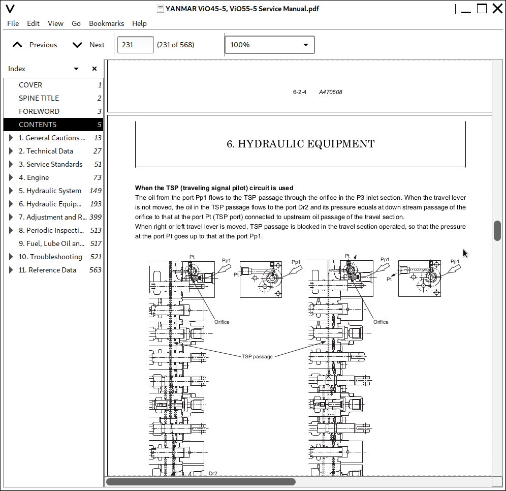
![]()