
Yanmar MARINE DIESEL ENGINE 6LY2-STE, 6LY2A-STP, 6LYA-STP Repair Service Manual
Complete service repair manual with Electrical Wiring Diagrams for Yanmar MARINE DIESEL ENGINE 6LY2-STE, 6LY2A-STP, 6LYA-STP, with all the technical information to maintain, diagnose, repair, and rebuild like professional mechanics.
Yanmar MARINE DIESEL ENGINE 6LY2-STE, 6LY2A-STP, 6LYA-STP workshop service repair manual includes:
* Numbered table of contents easy to use so that you can find the information you need fast.
* Detailed sub-steps expand on repair procedure information
* Numbered instructions guide you through every repair procedure step by step.
* Troubleshooting and electrical service procedures are combined with detailed wiring diagrams for ease of use.
* Notes, cautions and warnings throughout each chapter pinpoint critical information.
* Bold figure number help you quickly match illustrations with instructions.
* Detailed illustrations, drawings and photos guide you through every procedure.
* Enlarged inset helps you identify and examine parts in detail.
PRODUCT DETAILS:
Total Pages: 234 pages
File Format: PDF (Internal Links, Bookmarked, Table of Contents, Searchable, Printable, high quality)
Language: English
HINSHI-H8-011-1 - Yanmar MARINE DIESEL ENGINE 6LY2-STE, 6LY2A-STP, 6LYA-STP Service Manual.pdf
MAIN SECTIONS
COVER...1
COVER...2
FOREWORD...4
INDEX...5
CHAPTER 1.GENERAL...6
1.Exterior Views...13
2.Specifications...14
3.Performance Curves...16
4.Dimensions...19
5.Wiring Diagrams...23
6.Piping Diagrams...26
CHAPTER 2.INSPECTION AND SERVICING OF BASIC ENGINE PARTS...27
1.Cylinder Block...28
1-1.Inspection of parts...28
1-2.Cleaning of oil holes...28
1-3.Color check procedure ...28
1-4.Replacement of cup plugs...29
1-5.Cylinder bore measurement...30
2.Cylinder Head...32
2-1.Inspecting the cylinder head...33
2-2.Valve seat correction procedure...34
2-3.Intake/exhaust valves,valve guides...34
2-4.Valve springs...36
2-5.Assembling the cylinder head...37
2-6.Measuring top clearance...37
2-7.Intake and exhaust valve arms...37
2-8.Adjustment of valve clearance...38
2-9.Checking and adjusting the fuel injection timing...39
3.Piston and Piston Pins...40
3-1.Piston...40
3-2.Piston Pin...41
3-3.Piston rings...41
4.Connecting Rod...44
4-1.Inspecting the connection rod...44
4-2.Crank pin bearing...45
4-3.Piston pin bearing...45
4-4.Assembling piston and connecting rod...46
5.Crankshaft and Main Bearing...47
5-1.Crankshaft...47
5-2.Main bearing...49
6.Camshaft and Tappets...50
6-1.Camshaft...50
6-2.Tappets...51
7.Timing Gear...53
7-1.Inspecting the gears...53
7-2.Gear timing marks...54
8.Flywheel...55
8-1.Specifications of flywheel...55
8-2.Dimensions of flywheel and mounting flange...56
8-3.Ring gear...57
8-4.Position of top dead center and fuel injection timing...57
CHAPTER 3.FUEL INJECTION EQUIPMENT...58
1.Fuel injection Pump Construction...59
2.Fuel injection pump Specifications...60
3.Fuel supply System...61
3-1.Fuel supply system...61
3-2.Functioning of fuel injection pump...61
3-3.Injection volume control...62
3-4.Governor construction...63
3-5.Types of governor according to structure...64
3-6.Idling and Maximum speed...67
4.Fuel Injection Nozzle...68
4-1.Functioning of fuel injection nozzle...68
4-2.Fuel injection nozzle disassembly...69
4-3.Fuel injection nozzle inspection...69
4-4.Adjusting fuel injection nozzle...70
5.Fuel Feed Pump...71
6.Disassembly, Reassembly and Inspection of Governor...72
6-1.Governor disassembly...73
6-2.Inspection of governor...74
6-3.Assembling the governor...76
7.Disasembly,Reassembly and Inspection of Fuel injection pump...78
7-1.Disassembly of fuel injection pump...79
7-2.Inspection of fuel injection pump...82
7-3.Reassembly of fuel injection pump...83
7-4.Adjustment of Pre-stroke...86
7-5.Adjusting injection timing...87
7-6.Plunger pressure test...87
7-7.Delivery valve pressure test ...87
7-8.Adjusting injection volume(uniformity of each cylinder)...88
7-9.Adjustment of governor...88
7-10.Adjustment of torque rise...89
8.Automatic Advancing Timer...92
8-1.Timer construction...92
8-2.Function and characteristics of timer...92
8-3.Timer disassembly...93
8-4.Timer inspection...93
8-5.Timer reassembly...93
9.Fuel feed pump...94
9-1.Fuel Feed Pump Disassembly...94
9-2.Fuel Feed Pump Inspection...94
9-3.Fuel Feed Pump Reassembly...94
9-4.Fuel Feed Pump Adjustment...95
10.Adjustment of Fuel Injection Pump and Governor...96
10-1.Preparations...96
10-2.Nozzle inspection...97
10-3.Fuel injection nozzle reassembly...97
11.Fuel Filter...98
11-1.Fuel filter specifications...98
11-2.Fuel filter inspection...98
CHAPTER 4.TURBOCHARGER SYSTEM...99
1.Construction and Function...100
1-1.Outline...100
2.Standards for Maintenance and Check...101
2-1.Standards for Maintenance and Check...101
2-2.Tightening Torque...102
3.Periodical Checking Procedure...103
3-1.Periodical Checking Interval ...103
3-2.Checking Procedure...103
4.Disassembly Procedure...105
4-1.Preparations for Disassembly...105
4-2.Check before Disassembly...106
4-3.Disassembly...106
5.Cleaning and Checking Procedure...107
5-1.Cleaning...107
5-2.Checking Procedure...109
6.Reassembling procedure...112
6-1.Preparations for Reassembly...112
6-2.Reassembling procedure...112
7.Handling After Reassembly...115
7-1.Precautions for mounting the turbocharger to the engine...115
8.Troubleshooting...116
8-1.Exhaust gas is dense...116
8-2.Whitish exhaust gas...117
8-3.Too early oil shortage...117
8-4.Output drop...117
8-5.Poor follow-up of supercharger...117
8-6.Unusual sound or vibration...118
CHAPTER 5.LUBRICATION SYSTEM...119
1.Lubrication System...120
2.Lube Oil Pump...121
2-1.Lube oil pump construction...121
2-2.Specifications of lube oil pump...121
2-3.Removal...123
2-4.Inspection...123
2-5.Instllation...123
3.Lube Oil Filter...124
3-1.Lube oil filter construction...124
3-2.Lube oil filter replacement...124
4.Oil Pressure Control Valve...125
4-1.Oil pressure control valve construction...125
4-2.Oil pressure control valve replacement...125
5.Lube Oil Cooler...126
5-1.Lube oil cooler construction...126
5-2.Inspecting the lube oil cooler...126
6.Piston Cooling Nozzle...127
6-1.Piston cooling nozzle construction...127
6-2.Inspection of piston cooling nozzle...127
7.Rotary Waste Oil Pump(Optional)...128
7-1.Construction...128
7-2.Inspection the waste oil pump...128
CHAPTER 6.COOLING WATER SYSTEM...129
1.Cooling Water System...130
1-1.System...130
1-2.Water leakage test(Fresh water)...131
1-3.Removing Scale(During Disassembly)...131
1-4.Anti-Corrosion Agent...131
1-5.Antifreeze...131
2.Sea Water Pump...132
2-1.Sea water pump construction and functioning...132
2-2.Sea water pump disassembly...133
2-3.Sea water pump inspection...133
2-4.Sea water pump reassembly...133
3.Fresh Water Pump...134
3-1.Fresh water pump construction...134
3-2.Specifications of fresh water pump...135
3-3.Fresh water pump disassembly...135
3-4.Fresh water pump reassembly...135
4.Fresh Water Cooler...137
4-1.Fresh water cooler construction...137
4-2.Specifications of heat exchanger...138
4-3.Disassembly and reassembly of the fresh water cooler...138
4-4.Fresh water cooler inspection...138
5.Pressure Cap and Sub Tank...139
5-1.Pressure cap construction...139
5-2.Pressure cap pressure control...139
5-3.Pressure cap inspection...139
5-4.Function of the sub tank...139
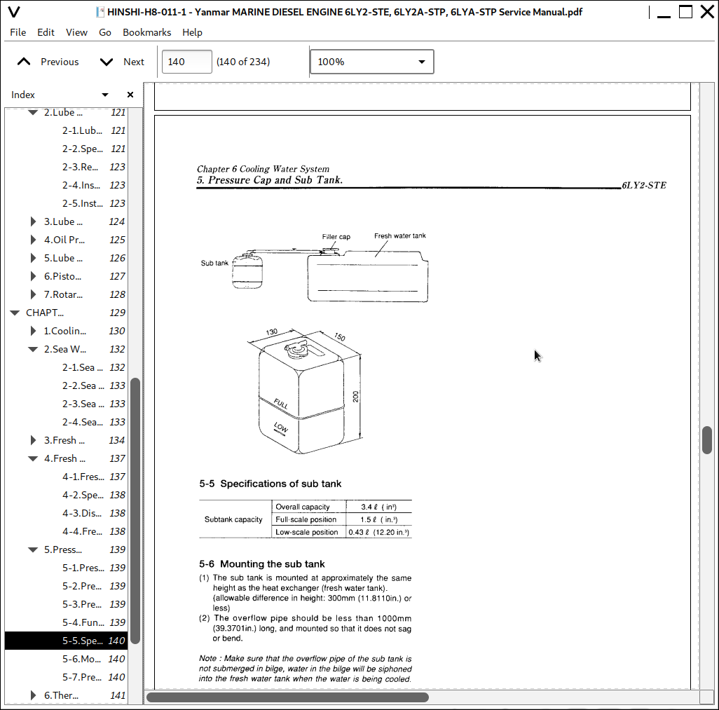
5-5.Specifications of sub tank...140
5-6.Mounting the sub tank...140
5-7.Precautions on usage of the sub tank...140
6.Thermostat...141
6-1.Functioning of thermostat...141
6-2.Thermostat construction...141
6-3.Characteristics of thermostat...141
6-4.Thermostat inspection...142
6-5.Testing the thermostat...142
7.Kingston Cock(Optional)...143
7-1.Construction...143
7-2.Handling precautions...143
7-3.Inspection...143
CHAPTER 7.REDUCTION AND REVERSING GEAR...144
1.Specification and System...145
1-1.Marine Gears(YANMAR MODEL KMH6A1)...145
2.Readdembly and disassembly(KMH6A1)...149
2-1.Disassembly...149
2-2.Disassembling input and output gears...150
2-3.Disassembling support shafts A and B...150
2-4.Disassembling valve body...151
3.Cautions for Reassembly...152
3-1.Cautions for Reassembly...152
3-2.Tightening Torque of Major Bolts...154
3-3.Standerd Tightening Torque...154
CHAPTER 8.REMOTO CONTROL(OPTIONAL)...155
1.Remoto Control System(Option)...156
1-1.Construction of remoto control system...156
1-2.Remoto control device components...156
2.Remoto Control Installation...157
2-1.Speed control...157
2-2.Ahead-neutral-astern control...157
CHAPTER 9.ELECTRICAL SYSTEM...158
1.System Diagram...159
1-1.System diagram of electric parts...159
2.Battery...160
2-1.Construnctlon...160
2-2.Battery capacity and battery cables...160
2-3.Inspection...160
2-4.Charging...162
2-5.Battery storage precautions...162
3.Starter Motor...163
3-1.Specifications and Performance...163
3-2.Features...163
3-3.Construction...164
3-4.Disassembly...165
3-5.Maintenance standerd...167
3-6.Inspection...168
3-7.Reassembly precautions...170
3-8.Adjustment and performance test...170
3-9.Testing...171
3-10.Troubleshooting...172
4.Alternator...173
4-1.Features...173
4-2.Specifications...173
4-3.Characteristics...173
4-4.Construction...174
4-5.Alternator functioning...175
4-6.Handling precautions...175
4-7.Disassembling the alternator...176
4-8.Inspection and adjustment...177
4-9.Reassembling the alternator...179
4-10.Performamce test...180
4-11.Troubleshooting...181
5.Instrument Panel...183
6.Warning Devices...184
6-1.Oil pressure alarm...184
6-2.Cooling water temperature alarm...185
6-3.Sender unit for lube pressure gauge...185
6-4.Sender unit for the cooling water temperature gauge...186
7.Tachometer...187
7-1.Construction of tachometer...187
7-2.Specifications and dimensions of tachometer...187
7-3.Measurement of sensor unit characteristics...188
7-4.Diagnosis...188
CHAPTER 10.DISASSEMBLY AND REASSEMBLY...189
1.Disassembly and Reassembly precautions...190
2.Disassembly and Reassembly Tools...191
2-1.Special Handtools...194
2-2.Measuring Instruments...196
2-3.Other material...197
3.Disassembly and Reassembly...200
3-1.Disassembly...200
3-2.Reassembly...206
4.Main parts spec./ tightening torque...219
4-1.Quality control points...219
4-2.Dimension of Main Parts...223
4-3.Bolt/Nut Tightening torque...226
5.Test running...227
5-1.Preliminary Precautions...227
5-2.Check Points and Precautions During Running...227
CHAPTER 11.TROUBLESHOOTING...228
1.Troubleshooting...229
BACK COVER...234
Yanmar MARINE DIESEL ENGINE 6LY2-STE, 6LY2A-STP, 6LYA-STP Repair Service Manual
![]()