
Yanmar Marine Diesel Engine 4LHA-STE, 4LHA-STZE, 4LHA-STP, 4LHA-STZP, 4LHA-DTE, 4LHA-DTZE, 4LHA-DTP, 4LHA-DTZP, 4LHA-HTE, 4LHA-HTZE, 4LHA-HTP, 4LHA-HTZP Repair Service Manual (M9961-H11341)
Complete service repair manual with Electrical Wiring Diagrams for Yanmar Marine Diesel Engines Model 4LHA-STE, 4LHA-STZE, 4LHA-STP, 4LHA-STZP, 4LHA-DTE, 4LHA-DTZE, 4LHA-DTP, 4LHA-DTZP, 4LHA-HTE, 4LHA-HTZE, 4LHA-HTP, 4LHA-HTZP, with all the technical information to maintain, diagnose, repair, rebuild like professional mechanics.
Yanmar Marine Diesel Engine (4LHA-STE/STZE/STP/STZP, 4LHA-DTE/DTZE/DTP/DTZP, 4LHA-HTE/HTZE/HTP/HTZP) workshop service repair manual includes:
* Numbered table of contents easy to use so that you can find the information you need fast.
* Detailed sub-steps expand on repair procedure information
* Numbered instructions guide you through every repair procedure step by step.
* Troubleshooting and electrical service procedures are combined with detailed wiring diagrams for ease of use.
* Notes, cautions and warnings throughout each chapter pinpoint critical information.
* Bold figure number help you quickly match illustrations with instructions.
* Detailed illustrations, drawings and photos guide you through every procedure.
* Enlarged inset helps you identify and examine parts in detail.
PRODUCT DETAILS:
Total Pages: 400 pages
File Format: PDF (Internal Links, Bookmarked, Table of Contents, Searchable, Printable, high quality)
Language: English
M9961-H11341 - Yanmar Marine Diesel Engine (4LHA-STE_STZE_STP_STZP, 4LHA-DTE_DTZE_DTP_DTZP, 4LHA-HTE_HTZE_HTP_HTZP) Service Manual.pdf
MAIN SECTIONS
TABLE OF CONTENTS
CHAPTER 0 FOR SAFETY
1. FOR SAFE SERVICING .... 0-1
2. PRECAUTION FOR SAFE SERVICING ...O-2
(A) Service Shop (Place) ... 0-2
(B) Working Wear .. 0-3
(G) Tools to Be Used .... 0-3
(D) Use of Genuine Parts, Oil and Grease
(E) Bolt and Nut Tightening Torques ...
(F) Electrical Parts ..
(G) Waste Treatment ..
(H) Handling the Product ... 0-5
3 LOCATION OF PRODUCT SAFETY LABELS .... 0-6
CHAPTER 1 GENERAL
1. Exterior Views ..... 1—1
2. Specifications ... 1’2
3. Service Standards ..... 1—3
4. Performance Curves .... 1—5
5. Dimensions .... 1—6
6. Piping Diagrams .. .. 1—7
7. Eiectrical Diagrams ... 1-8
CHAPTER 2 BASIC ENGINE
1. Disassembly and ReassemnyTools ... 2—1
2. Cylinder Block ..... 2-9
3. Cylinder Liners .... 212
4. Cylinder Head ... 2-14
5. Piston and Piston Pins . 2-21
6. Connecting Rod .. 2-25
7. Crankshaft and Main Bearing .. 2-28
8. Camshaft and Tappets . 2- 32
9. Timing Gear ... 2- 35
10. Flywheel . 2 36
CHAPTER 3 FUEL INJECTION EQUIPMENT
3-1. DISTRIBUTOR TYPE
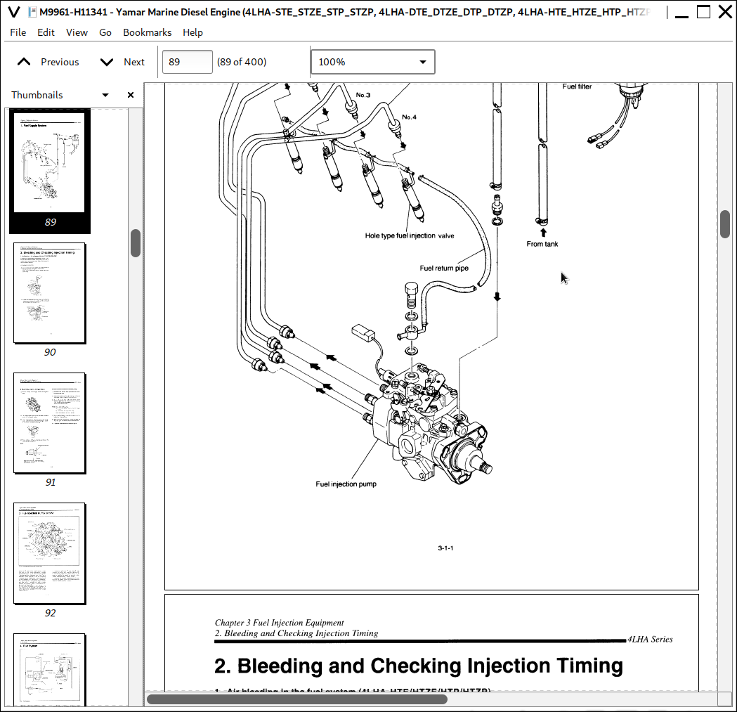
1. Fuel Supply System .. 3-1-1
2. Bleeding and Checking Injection Timing ... 3-1-2
3. Fuel Injection Pump Outline .... 3-1—4
4. Fuel System .... 3-1-5
5. Injection Pump Construction and Operation ..... 3-1-6
6. Goverming Mechanism ... 3-1—16
7. Timer Construction and Operation... .. 3-1-38
8. Magnet Valve ... 3-1-43
9. Pump Reassembly, Adjustment and Inspection .. 3-1-44
10. Test Bench Adjustment of VE Pump ... 3-1-52
11. Troubleshooting ... 3-1-55
12. Fuel Injection Nozzle .. 3-1-59
13. Fuel Filter .. 3-1-63
3-2. YPES-AL TYPE
1. Fuel Supply System . 3-2-1
2. Disassembiy,Reassembly and Inspection of Governor .... 3-2-15
3. Disassemblyfleassembiy and Inspection of Fuel Injection Pump .. 3-2-21
4. Adjustment of Fuel Injection and Governor .. 3-2-31
5. Automatic Advancing Timer ... 3-2-38
6. Fuel Feed Pump ... 3-2-40
7. Fuel Injection Nozzle .... 3-2-43
8. Troubleshooting ... .. 3-2-48
9. Tools .. 3—2-50
0. Fuel Injection Pump Specifications .. 3-2-53
1. Service Date .... 3-2-54
CHAPTER 4 INTAKE AND EXHAUST SYSTEM
1. Intake and Exhaust System ..... 4-1
2. Intake Silencer . .4-2
3. Intake Manifold .... 4-3
4. Turbocharger ... 4—4
5. Mixing Elbow .. 4-26
6. Breather ... 4-27
CHAPTER 5 LUBRICATION SYSTEM
1. Lubrication System ... 5-1
2. Lube Oil Pump . .. 5-3
3. Lube Oil Filter ... 5-6
4. Oil Pressure Control Valve . 5-8
5. Lube Oil Cooler ... .. 5—9
6. Piston Cooling Nozzle .. 5-10
7. Rotary Waste Oil Pump (Optional) ... 5-11
CHAPTER 6 COOLING WATER SYSTEM
1. Cooling Water System . 6-1
2. Sea Water Pump ..... 6-4
3. Fresh Water Pump. .. 6-7
4. Heat Exchanger ... 6-10
5. Pressure Cap and Sub Tank. .. 6-12
6. Thermostat ..... 6-14
7. Kingston Cock (Optional) .... 6-16
8. Sea Water Filter (Optional) .... 6-17
9. Bilge Pump and Bilge Strainer (Optional) ... 6—18
CHAPTER 7 REDUCTION AND REVERSING GEAR
7-1. Marine gear model KM5A
1. Construction .... 7-1-1
2. Shifting Device .... 7-1-5
3. Inspection and Servicing ... 7-1-10
4. Special Tools ... .. 7-1-20
5. Disassembly .... 7-1-21
6. Reassembly ... 7-1-29
7-2. Marine gear model HSW630A1
1. Construction .... 7-2-1
2. Shifting Device .... 7-2-2
3. Inspection and Servicing ... 7—2-6
4. Disassembly .. .. 7-2-9
5, Reassembly ... 7-2-23
CHAPTER 8 REMOTE CONTROL (OPTIONAL)
1. Remote Control System .. 8-1
2. Remote Control Installation ..... 8-2
3. Remote Control Inspection ..... 8-5
4. Remote Control Adjustment ... 8-6
CHAPTER 9 ELECTRICAL SYSTEM
1. System Diagram .... 9-1
2. Battery .. 9~3
3. Starter Motor . 9—7
4. Alternator ... 9-17
5. Instrument Panel .... 9—35
6. Warning Devices... .. 9-37
7. Tachometer ... 9-40
Yamar Marine Diesel Engine (4LHA-STE/STZE/STP/STZP, 4LHA-DTE/DTZE/DTP/DTZP, 4LHA-HTE/HTZE/HTP/HTZP) Service Manual
![]()