
Komatsu Forklift Series 4032 (FB13M-2R, FB15-2R, FB15M-2R, FB16-2R, FB16M-2R, FB18-2R, FB18M-2R, FB20-2R, FB20M-2R) Repair Service Manual
Complete service repair manual with Electrical Wiring Diagrams for Komatsu Forklift Series 4032 (FB13M-2R, FB15-2R, FB15M-2R, FB16-2R, FB16M-2R, FB18-2R, FB18M-2R, FB20-2R, FB20M-2R), with technical information to maintain, diagnose, repair, and service like professional mechanics.
Komatsu Forklift Series 4032 (FB13M-2R, FB15-2R, FB15M-2R, FB16-2R, FB16M-2R, FB18-2R, FB18M-2R, FB20-2R, FB20M-2R) workshop service repair manual includes:
* Numbered table of contents easy to use so that you can find the information you need fast.
* Detailed sub-steps expand on repair procedure information
* Numbered instructions guide you through every repair procedure step by step.
* Troubleshooting and electrical service procedures are combined with detailed wiring diagrams for ease of use.
* Notes, cautions and warnings throughout each chapter pinpoint critical information.
* Bold figure number help you quickly match illustrations with instructions.
* Detailed illustrations, drawings and photos guide you through every procedure.
* Enlarged inset helps you identify and examine parts in detail.
PRODUCT DETAILS:
Total Pages: 378 pages
File Format: PDF (Internal Links, Bookmarked, Table of Contents, Searchable, Printable, high quality)
Language: English
40328042305 EN - Komatsu Forklift Series 4032 (FB13M-2R, FB15-2R, FB15M-2R, FB16-2R, FB16M-2R, FB18-2R, FB18M-2R, FB20-2R, FB20M-2R) Shop Manual.pdf
604.24.128 - Komatsu ELECTRONIC EQUIPMENT FORKLIFT TRUCKS FB 12M-1R, FB 15M-1R, FB 18M-1R, FB 15-1R FB18-1R, FB 18H-1R, FB 20H-1R, FB 20GH-1R, FB 22H-1R, FB 25-1R, FB 28-1R, FB 30-1R.pdf
FB13M(V)_30H.1E(ELE)-BE1 - Komatsu Forklift Truck Controller for Electric Lift Trucks (FB13MV_16MV-1E, FB16M_18M_20M-1E, FB16_18_20-1E, FB16H_20H_25H_30H-1E, FB16GH_20GH_25GH-1E) Shop Manual 1 of 2.pdf
FB13M(V)_30H.1E(ELE)-BE1 - Komatsu Forklift Truck Controller for Electric Lift Trucks (FB13MV_16MV-1E, FB16M_18M_20M-1E, FB16_18_20-1E, FB16H_20H_25H_30H-1E, FB16GH_20GH_25GH-1E) Shop Manual 2 of 2.pdf
Komatsu Forklift MJ-2E Series (FB13 • 15MJ-2E) Shop Manual.pdf
Komatsu Forklift Truck AM-3E_AM-2E Series Service Training Material.pdf
MAIN SECTIONS
40328042305...1
Header...3
Table of contents...3
00 General Information...11
Product information...11
Instruction and maintenance manual...11
General Forklift Description...11
Definition of travel direction...12
Overall dimensions for three-wheel truck...13
Three-wheel truck technical data...14
Overall dimensions for four-wheel truck...18
Four-wheel truck technical data...19
Three-wheel truck tyre characteristics...23
Four-wheel truck tyre characteristics...23
Fork lift truck capacities - Model 1300 kg 3 wheels - with vertical masts and forks = 1400 mm max...24
Fork lift truck capacities - Model 1500 kg 3 / 4 wheels - with vertical masts and forks = 1400 mm max...27
Fork lift truck capacities - Model 1600 kg 3 / 4 wheels - with vertical masts and forks = 1400 mm max...30
Fork lift truck capacities - Model 1800 kg 3 / 4 wheels - with vertical masts and forks = 1400 mm max...33
Fork lift truck capacities - Model 2000 kg 3 / 4 wheels - with vertical masts and forks = 1400 mm max...36
Alternative lift characteristics...39
Abbreviations key...40
Tyre inflation pressure...41
Lamps...41
Battery dimensions and weights...41
Internal accessibility...42
Safety features...43
Transporting the Forklift...45
Forklift towing...46
Loading and unloading the truck...47
Safety precautions...49
Description of safety symbols...49
Operations Preliminary to Maintenance...49
To avoid accidents...49
General safety Regulations...50
Safety Regulations Relative to Operating Materials...52
01 Service...55
Servicing...55
Preliminary operations before commissioning...55
Synoptic Table of Maintenance Operations...55
Supply Table...56
02 Diagnostics...57
Diagnostic software...57
Connection between the diagnostics PC and the forklift ...57
Software...58
Description of the menus in the WINPCCONSOLE software...59
Description of the PARAMETER menu ...63
Description of the TESTER menu...68
TESTER / Diagnostics Function...69
Parameters...72
Introduction...72
Parameters of the DUAL AC module...72
Parameters of the AC2 FLASH module...78
...80
...81
Parameters of the ECO DISPLAY module...81
Parameterisation of the drive function...85
Parameterisation of the steering function...86
Parameterisation of the electric braking function...87
Parameterisation of the battery state monitoring function...88
Parameterisation of the lifting function...88
Parameterisation of the hydraulically assisted steering function...89
Parameterisation of the tilt, side shift (SLI) and 4th lever functions...90
Alarms...91
State of the truck during an alarm situation...91
...91
...92
Alarms list...93
Analogue signals...108
Summary of signals from the analogue transducers...108
11 Traction motor...111
Asynchronous motors...111
Features of the asynchronous motors ...111
Checking the asynchronous motors ...113
Front axle motors...114
Traction motor technical data...114
Traction...114
Traction motor...116
Drive motor checks...118
Drive motor decomposition...120
Encoder...122
Replacing the traction encoder...122
Electrical connections of the traction motors...123
Temperature sensor KTY84...124
Insulation testing of traction motor...126
22 Transmission...127
Front axle...127
Front axle technical data...127
Removal of front axle with traction motors...130
Front axle reassembly...133
Reducer...134
Front axle reducer gearbox topography...134
Front axle reduction gear disassembly/reassembly...135
Removal / reassembly of the drive wheel reducer gearbox...136
Check reducer gearbox oil level...137
Reducer gearbox oil change...138
31 Truck...139
Counterweight...139
Counterweight removal...139
Counterweight reassembly...144
Covers...146
Cover topography...146
Side covers removal / reassembly...147
Battery cover removal / reassembly...148
Step plate removal / reassembly...150
Distributor cover removal / reassembly...152
Batteries...155
Battery removal...155
34 Driver's seat...157
Overhead guard...157
Removal of the overhead guard...157
Reassembly of the overhead guard...159
Fairings...160
Removal / reassembly of the steering column panelling...160
Removal / reassembly of the control panel panelling...161
42 Steering system...165
Steering distributor...165
Steering distributor technical data...165
Removal / reassembly of the steering distributor...167
Steering distributor pressure switch technical data...169
Replacing the steering distributor pressure switch...170
Steering column...171
Removal / reassembly of the steering column...171
Fifth-wheel steering axle...175
Three-wheel truck rear axle technical data...175
Three-wheel truck axle removal...178
Three-wheel truck axle reassembly...181
Three-wheel axle disassembly...183
Three-wheel truck potentiometer technical data...187
Replacement of the three-wheel steering axle potentiometer...189
Four-wheel truck axle technical data...190
Four-wheel axle removal...191
Four-wheel truck axle reassembly...192
Four-wheel axle disassembly...194
Four-wheel truck potentiometer technical data...199
Replacing the four-wheel truck potentiometer...200
Lubricating the steering axle...205
46 Wheels and tyres...207
General information...207
Safety regulations for wheels and rims...207
General information for changing tyres...207
Tyrewear check...209
Wheel change...210
Wheel change...210
Wheel decomposition...213
Disassembly/assembly of tyres on rims with movable flange...213
Quick tyres assembly/disassembly...214
Tightening torques...216
Check wheel nut tightness (every 10 hours during run-in)...216
49 Braking system...217
Parking brake...217
Removal / reassembly of the parking brake lever...217
Parking brake control cable replacement...219
Replacing the parking brake microswitch...221
Parking brake adjustment...223
Service brake...224
Service brake pedal removal...224
Service brake pedal reassembly...225
Stop lights microswitch replacement...226
Replacing the service brake pedal potentiometer...226
Braking group...228
Removing / installing the brake group...228
50 Controls...233
Accelerator pedal...233
Accelerator pedal...233
Accelerator pedal potentiometer...233
56 Display elements...235
DISPLAY...235
Plate data...235
Connector...235
Multifunction panel...236
Setting the date and time...242
Speed reductions...246
Functionality of the display buttons...247
Data modification pushbutton functions...249
Multifunction panel removal / reassembly...250
Alarms...251
60 Electronic system...255
Software versions...255
Reference software versions...255
Electronic traction system...256
Characteristics of the electronic drive system...256
Plate data: traction...257
Connectors...257
Closing the general contactor...260
Thermal sensor operation...260
Hydraulic functions electronic system...261
Functions of the AC2 module...261
Plate data: pump...262
AC2 Connectors...262
Control of the general contactor...263
Lowering solenoid valve operation...264
Thermal sensor operation...264
Types of hours counters...265
Types of hour counters:...265
Hours counter management in case of electronic system replacement ...265
Resetting the machine hours...266
Electrical system components...267
Electronics panel technical data...267
Electronics panel removal / reassembly...267
Protection of the electrical system...272
Emergency pushbutton ...273
Replacing the emergency stop button...273
Assembly / disassembly of the lights switch (option)...274
Lamp replacement (if applicable)...276
Work light replacement procedure (optional)...277
Contactors...278
Location of Fuses...279
Changing a fuse...280
DC/DC Converter ...281
Buzzer...282
Fans...282
Encoder description...282
71 Hydraulic components...285
Hydraulic circuit...285
Layout of hydraulic parts...285
Hydraulic system assembly diagram...286
Pump motor...289
Pump motor technical data...289
Pump motor removal...290
Pump motor reassembly...294
Replacing the pump...295
Replacing the pump motor encoder ...297
Replacing the pump motor temperature sensor...298
Oil tank...299
Hydraulic oil tank...299
Oil tank removal / reassembly...300
Check hydraulic tank oil level...303
Hydraulic distributor...305
Hydraulic distributor technical data...305
Hydraulic distributor removal / reassembly...306
Replacing the hydraulic distributor probe...309
Valves...310
Safety valve (load lowering block) (VBDC)...310
Safety valve layout...311
Tilt cylinders...317
Tilt cylinders...317
Tilt cylinder removal / reassembly...317
Air bleeding of the tilt cylinders...320
80 Lifts...321
Lifts...321
Technical data for service...321
Lift typologies...322
Simplex Lift...325
Duplex Lift...329
Triplex Lift...334
Load chain locking device...340
Fork carriage retaining device...340
Assembly of the mast / carriage support rollers...340
Check...342
Disassembly of the Simplex lift cylinder...343
Disassembly of the side cylinders of the Duplex lift...344
Disassembly of the side cylinders of the Triplex lift...346
Duplex / Triplex central cylinder...348
Limit stop dampers...350
Disassembly of the fork carriage...351
Tilt cylinder...352
Lift disconnection...354
Lift reassembly...357
Air bleeding of the lift cylinders...358
Lift cylinders...360
Annex...369
A Diagrams...371
Wiring diagrams...371
Electrical circuit diagram 40328020002...371
Electrical connection diagram 40328020001...373
Hydraulic diagrams...375
Hydraulic diagram 40328082502...375
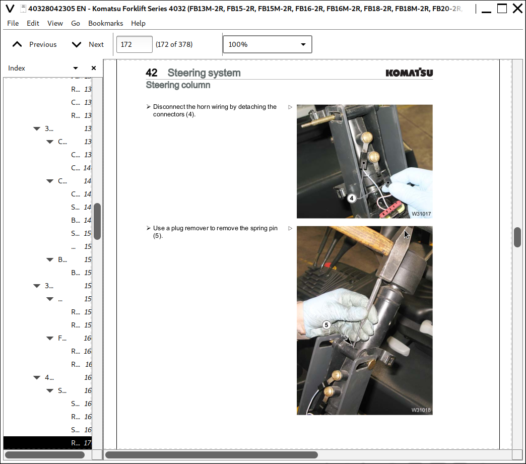
![]()