
Komatsu Forklift Series 4024 (FB22H-3R, FB25H-3R, FB25HG-3R, FB30H-3R) Repair Service Manual
Complete service repair manual with Electrical Wiring Diagrams for Komatsu Forklift Series 4024 (FB22H-3R, FB25H-3R, FB25HG-3R, FB30H-3R), with all the technical information to maintain, diagnose, repair, rebuild like professional mechanics.
Komatsu Forklift Series 4024 (FB22H-3R • FB25H-3R • FB25HG-3R • FB30H-3R) workshop service repair manual includes:
* Numbered table of contents easy to use so that you can find the information you need fast.
* Detailed sub-steps expand on repair procedure information
* Numbered instructions guide you through every repair procedure step by step.
* Troubleshooting and electrical service procedures are combined with detailed wiring diagrams for ease of use.
* Notes, cautions and warnings throughout each chapter pinpoint critical information.
* Bold figure number help you quickly match illustrations with instructions.
* Detailed illustrations, drawings and photos guide you through every procedure.
* Enlarged inset helps you identify and examine parts in detail.
PRODUCT DETAILS:
Total Pages: 286 pages
File Format: PDF (Internal Links, Bookmarked, Table of Contents, Searchable, Printable, high quality)
Language: English
60424171 EN - Komatsu Forklift Series 4024 (FB22H-3R • FB25H-3R • FB25HG-3R • FB30H-3R) Shop Manual.pdf
MAIN SECTIONS
40248042304...1
Header...3
Table of contents...3
00 General information...9
Product information...9
Instruction and maintenance manual...9
Definition of Direction of Travel...10
General Forklift Description...10
Overall dimensions...11
Technical Data...11
Tyre characteristics...14
Forklift capacities - Model 2200 kg - Masts vertical with forks = 1400 mm max...15
Forklift capacities - Model 2500 kg short pitch - Masts vertical with forks = 1400 mm max...17
Forklift capacities - Model 2500 kg long pitch - Masts vertical with forks = 1400 mm max...19
Forklift capacities - Model 3000 kg - Masts vertical with forks = 1400 mm max...21
Alternative lift characteristics...23
Abbreviations key...24
Pneumatic tyre inflation pressure...24
Lamps...24
Battery dimensions and weights...25
Internal accessibility...26
Safety Devices...27
Transporting the Forklift...29
Forklift Towing...30
Loading and Unloading the Forklift...31
Safety precautions...32
Description of safety symbols...32
Operations Preliminary to Maintenance...32
To avoid accidents...32
General safety Regulations...33
Safety Regulations Relative to Operating Materials...36
01 Service...37
Maintenance...37
Preliminary operations before commissioning...37
Synoptic Table of Maintenance Operations...37
Supply Table...38
02 Diagnostics...39
Diagnostic software...39
Connection between the diagnostics PC and the forklift ...39
Software...40
Description of the menus in the WINPCCONSOLE software...42
Description of the PARAMETER menu ...46
Description of the TESTER menu...51
Parameters...53
Introduction...53
Parameters of the DUAL AC Master module ...54
AC3 module parameters...60
Smart Display...65
TESTER Function...69
Speed reductions...72
Alarms...73
General information on the alarms...73
Alarms of the DUAL AC module...74
Alarms of the AC3 module ...84
Alarms of the SMART DISPLAY module ...90
Analogue signals...92
Analogue signal acquisition...92
11 Drive motor...93
Asynchronous motors...93
Features of the asynchronous motors ...93
Checking the asynchronous motors ...96
Front axle motors...98
Drive motor technical data...98
Drive motor checks...101
Motor temperature sensor...104
Drive motor decomposition...106
22 Gearbox...109
Front axle...109
Front axle technical data...109
Front axle layout...111
Removal of front axle with drive motors...112
Front axle reconnection...118
Front axle disassembly...119
Front axle reassembly...120
Reducer...121
Front axle reducer layout...121
Front axle reduction gear disassembly/reassembly...122
Reduction gear oil level check...125
Reducer oil change...125
31 Vehicle...127
Bonnets...127
Bonnet layout...127
Right side bonnet removal/reassembly...128
Left side bonnet removal/reassembly...129
Battery hood removal/reassembly...129
Electronic panel bonnet removal/reassembly...133
Distributor hood removal/reassembly...133
Removal/reassembly of the operator footboard...135
Counterweight...137
Counterweight disconnection...137
Counterweight reconnection...140
34 Driver's seat...141
Fairing...141
Fairing removal/reassembly...141
Steering column panels removal/reassembly...143
Protective roof...145
Removal of the protective roof...145
Protective roof refitting...149
Lamp changes...150
42 Steering system...151
Hydraulic steering circuit...151
Power steering circuit tube connection diagram...151
Steering solenoid valve...152
Steering distributor technical data...152
Steering distributor removal...154
Steering distributor reassembly...156
Steering column...158
Steering column removal/reassembly...158
Replacement of the steering column joint...159
Steering axle...161
Steering axle technical data...161
Steering axle disconnection...162
Steering axle reconnection...165
Steering axle lubrication...166
Replacement of the steering axle bearings...167
Steering axle potentiometer...177
Replacement of the steering axle potentiometer...179
Steering cylinder...180
Steering cylinder disconnection...180
Steering cylinder reconnection...182
Replacement of the steering cylinder gaskets...183
Replacement of the cylinder connecting rod ball joints...184
46 Wheel and tyres...187
Miscellaneous...187
Safety regulations for wheels and rims...187
General information for changing tyres...188
Tyrewear check...189
Changing wheels...190
Changing the front wheel...190
Changing the rear wheel...191
Wheel disassembly...192
Disassembly/assembly of tyres on rims with movable flange...192
Quick tyres assembly/disassembly...194
Tightening torques...197
Tightening torques for single wheels...197
49 Brake system...199
Service brake...199
Brake pedal...199
Brake pedal potentiometer...199
Brake pedal removal/reassembly...200
Replacement of the brake pedal spring...201
Stop micro replacement...202
Replacement of the brake pedal potentiometer...203
Service brake adjustment...205
Parking brake...206
Microswitch features...206
Parking brake removal/reassembly...206
Parking brake wire replacement...208
Replacement of the parking brake microswitch...212
Parking brake adjustment...212
Brake group...214
Brake pad replacement...214
50 Controls...217
Accelerator pedal...217
Accelerator pedal...217
Accelerator pedal potentiometer...218
56 Display elements...221
Display...221
Multifunction panel...221
State of the display on ignition...225
State of the display during normal forklift operation...0
State of the display during an alarm situation...227
Plate data...229
Display operation ...231
60 Electrical system...233
CAN BUS...233
CAN BUS ...233
CAN BUS - Application ...236
Brake pedal potentiometer...237
Drive electrical system...239
Functions of the DUAL AC module...239
Plate data...241
DUAL AC connectors...242
Software program and parameterizations...246
Hydraulic functions electrical system...250
Functions of the AC3 module...250
Plate data...251
AC3 Connectors ...252
Software program and parameterizations...254
Electrical system components...257
Contactors...257
Fuses...258
DC/DC Converter ...259
Emergency pushbutton ...261
Buzzer...262
Fans...263
Encoder description...265
Lamps...267
Protection of the electrical system...269
71 Hydraulic equipment...271
Solenoid valve...271
Lifting hall sensor...271
Reed contacts...272
Annex...277
A Diagrams...279
Circuit diagrams...279
Electrical circuit plan - sheet 1/1...279
Hydraulic diagrams...281
Hydraulic system plan - sheet 1/1...281
Flow diagrams...283
Flow chart of functions on display...283
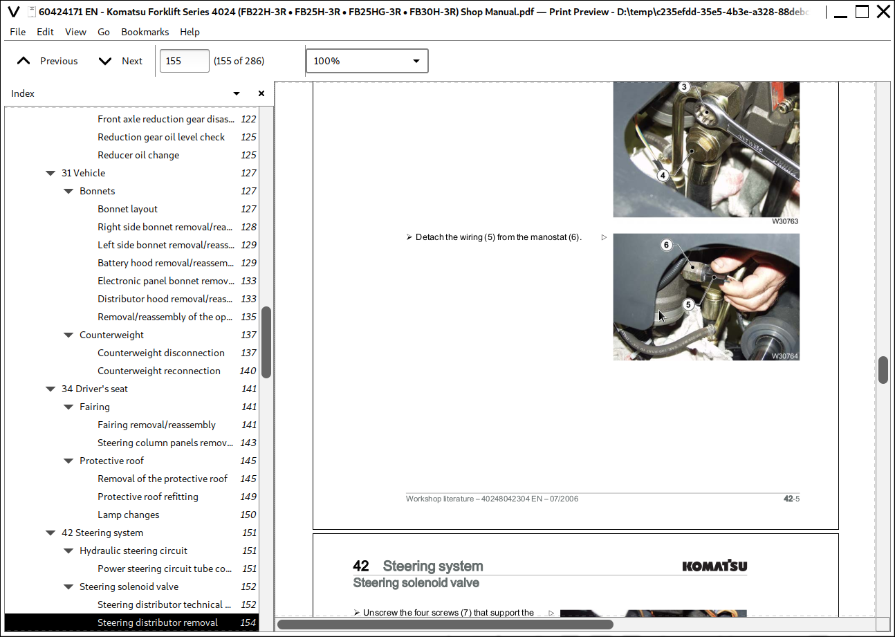
![]()