
Fendt Tractor 300-series (309/310/311/312) Vario Tractors Repair Service Manual
Complete service repair manual with Electrical Wiring Diagrams for Fendt Tractor 300-series (309/310/311/312) Vario Tractors, with all the technical information to maintain, diagnose, repair, and rebuild like professional mechanics.
Fendt Tractor 300-series (Vario 309/Vario 310/Vario 311/Vario 312) Tractors workshop service repair manual includes:
* Numbered table of contents easy to use so that you can find the information you need fast.
* Detailed sub-steps expand on repair procedure information
* Numbered instructions guide you through every repair procedure step by step.
* Troubleshooting and electrical service procedures are combined with detailed wiring diagrams for ease of use.
* Notes, cautions and warnings throughout each chapter pinpoint critical information.
* Bold figure number help you quickly match illustrations with instructions.
* Detailed illustrations, drawings and photos guide you through every procedure.
* Enlarged inset helps you identify and examine parts in detail.
X990.005.056.010 - Fendt Tractor 300-series (309/310/311/312) Vario COM III Workshop Manual.pdf
X990.005.059.001 - Fendt Tractor 300-series (309, 310, 311, 312) Vario COM III Workshop Manual.pdf
339.020.010.006 (3785-de) - FENDT 309 Vario, 310 Vario, 311 Vario, 312 Vario Betriebsanleitung.pdf
PRODUCT DETAILS:
Total Pages: 1,354 pages
File Format: PDF (Internal Links, Bookmarked, Table of Contents, Searchable, Printable, high quality)
Language: English
MAIN SECTIONS
0000 - Tractor / General system...3
A - General...3
Assembly overview...3
Documentation structure...7
Tightening torques for bolts in Nm...9
History of the FENDT 300 Vario agricultural tractor range...10
Towing instructions...19
B - Faults...20
Vario Tractors - Fault Codes...20
D - Component Location...41
Electrical / electronic components - A...41
Electrical / electronic components - B...44
Electrical / electronic components - E...52
Electrical / electronic components - G...56
Electrical / electronic components - H...57
Electrical / electronic components - K...58
Electrical / electronic components - M...60
Electrical / electronic components - R...62
Electrical / electronic components - S...63
Electrical / electronic components - X...71
Electrical / electronic components - Y...94
Hydraulic components...99
F - Setting and Calibration...105
General points on calibration...105
Calibration code 8001, 8002...106
Calibration code 7666...111
Calibration code 6034...114
Calibration code 7034...117
Calibration code 4001...120
Calibration code 4002...123
Calibration code 4005...126
Calibration code 4005...129
Calibration code 4007...132
Calibration code 4009...150
1005 - Transmission / transmission control unit...154
A - General...154
Functional schematic of transmission ML 75...154
Transmission - Emergency operating mode...160
Transmission control unit functional sequence...164
C - Documents and Diagrams...168
Transmission hydraulic system - Legend...168
E - Testing...174
Transmission pressure measurement...174
Testing clutch/turboclutch valve and valve block...176
1010 Transmission / Differential...183
G - Repair...183
Pinion shaft, diff. gears and ring gear - removing and installing...183
1015 Transmission / Axle drives...200
G - Repair...200
Installing and removing axle drives...200
Disassembly and reassembly of axle drives...206
1030 Transmission / Hand brake...212
F - Setting and Calibration...212
Setting hand brake...212
G - Repair...213
Removing and installing hand brake...213
1050 Transmission / Housing...216
G Repair...216
Disconnecting tractor, transmission and rear-axle housings...216
Connecting tractor, transmission and rear axle housings...222
1070 Transmission / brake system...227
C - Documents and Diagrams...226
Brake adjuster...226
G - Repair...227
Removing and installing rear wheel brake...227
Bleeding the hydraulic brake system...232
1080 - Transmission / Transmission unit...235
G - Repair...235
Removing Vario transmission unit...235
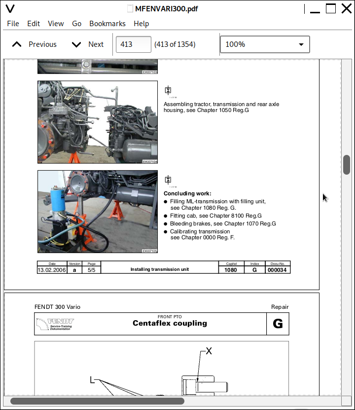
Installing transmission unit...240
1200 - Transmission / Front PTO...245
Assembly instruction Front PTO ...245
Centaflex coupling...245
Front PTO transmission and piping...246
Mounting and adjusting the seasonal disconnect mechanism...249
Finishing...250
1220 - Transmission / Live PTO...251
G - Repair...251
Removing and installing live PTO clutch...251
Removing and installing live PTO speed preselection...263
1320 - Transmission / Front wheel drive...278
G - Repair...278
Removing and installing front wheel drive clutch...278
2000 - Engine / General system...288
A - General...288
General description of the common rail system...288
Emergency operating mode...292
FENDT 300 Vario engine specifications...293
Determining engine power - comparison of standards and directives...295
Measuring PTO power...297
Zapfwellenleistung und Kraftstoffverbrauch...299
Belt drive Deutz TCD 2012...303
A051- ECU, engine control unit (EDC 7)...304
B055 - sensor, foot throttle...308
B085 - camshaft speed...309
B086 - rail pressure sensor...311
B087 - fuel low pressure and B090 - oil pressure sensor...312
B088 - Kurbelwellendrehzahl...313
B089 - Deutz temperature sensor...315
B091 - sensor, water in fuel...316
B092 - sensor, boost pressure / temperature...318
2010 - Engine / cylinder head...319
F - Setting and Calibration...319
Setting valve clearance...319
2060 - Engine / Fuel system...323
A - General...323
Water separator (prefilter)...323
Fuel delivery pump...324
Y091 - metering unit...325
High pressure accumulator (rail)...330
Design and function of the high pressure relief valve...332
Kraftstoff - System...334
Y095...Y101 - injector 1...6...336
Fuel plan FENDT 300 Vario...339
G - Repair...341
Removing and installing high pressure relief valve and rail pressure sensor...341
Bleeding the fuel system...344
Bleeding the fuel system...345
2250 - Engine / Engine Heather...347
G - Repair...347
Mounting engine heater and transmission oilheater...347
2312 - Engine / Lubrication...351
D - Component Location...351
Lube oil circuit...351
E - Testing...354
Lubrication pressure test...354
2400 - Engine / exhaust system...356
A - General...356
Y094 - actuator EGR (exhaust gas recirculation)...356
2712 - Engine / Injectors...359
G - Repair...359
Removing and installing injector...359
5500 - Air Conditioning System...371
Important Notes...371
Compressor installation...372
Mounting fitting condenser and fluid reservoir...373
Coolant lines...374
Evaporator and condensed water drain tube...380
Temperature control...382
Evacuating and filling air conditioning system...384
Checking the air conditioning system...385
Air conditioning system circuit diagram...386
8100 - Cab / General system...387
G - Repair...387
Remove cab...387
Fitting cab...397
8113 - Cab / Heater...406
G - Repair...406
Removing and installing M009 - heater blower...406
8117 - Cab / Windscreen Wippers...409
Mounting rear windscreen wipers...409
8610 - Power lift / Electrohydraulic control EPC...413
A - General...413
EPC - rear power lift...413
B - Faults...415
Troubleshooting table for power lift and service hydraulics (hydraulics)...415
C - Documents and Diagrams...416
Sectional view and circuit diagram of EHR 23 LS (Farmer 300C)...416
8800 - Air compressor / General system...419
C - Documents and Diagrams...419
Air compressor plan...419
D - Component Location...422
Position of components, air compressor...422
9000 - Electrics / General system...426
C - Diagram...426
FENDT 300 Vario COM III from 336 .. 0101- / 337 .. 0101- / 338 .. 0101- / 339 .. 0101-...426
Fuse holder X050, X051 and A013...428
Overview of components FENDT 300 Vario - pilot production...431
Overview of electrical circuit diagram - 339.900.000.003...446
Microfuse, instrument cluster, control panel - Sheet 2...447
Electronics box - Sheet 3...448
Grounding plan - Sheet 4...449
Power supply +UB - Sheet 5...450
Electronics power supply - Sheet 6...451
Lighting with horn - Sheet 7...452
Turn signal system - Sheet 8...453
Brake lamp, compressed air pilot control, hydraulic brake - Sheet 9...454
Wipers and rotating beacon - Sheet 10...455
Front work light - Sheet 11...456
Work light rear - Sheet 12...457
Heating - Sheet 13...458
Ventilation and air-conditioning system - Sheet 14...459
Heated rear window - Sheet 15...460
Sockets, seat compressor - Sheet 16...461
Implement socket - Sheet 17...462
Enhanced control bus (CAN bus) - Sheet 18...463
Instrument cluster - Sheet 19...464
Electronic power lift control - Sheet 20...465
Transmission bus - Sheet 21...466
Transmission control - Sheet 22...467
Transmission control - Sheet 23...468
Suspension - Sheet 24...469
PTO shafts - Sheet 25...470
4WD and differential lock - Sheet 26...471
3rd hydraulic circuit, brake load circuit - Sheet 27...472
Lighting, cab and radio - Sheet 28...473
Modasys data transfer - Sheet 29...474
EDC engine control - Sheet 30...475
Appendix relay position - Sheet 31...476
Appendix relay design - Sheet 32...477
Engine control - Sheet 33...478
FENDT 300 Vario COM III from 336 .. 1001- / 337 .. 1001- / 338 .. 1001- / 339 .. 1001-...479
Fuse holder X050, X051 and A013...480
Component overview FENDT 300 Vario starting with series production...484
Overview of electrical circuit diagrams - 339.900.000.004...499
Microfuse, instrument cluster, control panel - Sheet 2...500
Electronics box - Sheet 3...501
Grounding plan - Sheet 4...502
Power supply +UB - Sheet 5...503
Electronics power supply - Sheet 6...504
Lighting with horn - Sheet 7...505
Turn signal system - Sheet 8...506
Brake lamp, compressed air pilot control, hydraulic brake - Sheet 9...507
Wipers and rotating beacon - Sheet 10...508
Front work ligh - Sheet 11...509
Work light rear - Sheet 12...510
Heating - Sheet 13...511
Ventilation and air-conditioning system - Sheet 14...512
Heated rear window - Sheet 15...513
Sockets, seat compressor - Sheet 16...514
Implement socket - Sheet 17...515
Enhanced control bus (K-CAN bus) - Sheet 18...516
Instrument cluster - Sheet 19...517
Electronic power lift control - Sheet 20...518
Transmission bus (G-CAN bus) - Sheet 21...519
Transmission control - Sheet 22...520
Transmission control - Sheet 23...521
Suspension - Sheet 24...522
PTO shafts - Sheet 25...523
4WD and differential lock - Sheet 26...524
3rd hydraulic circuit, brake load circuit - Sheet 27...525
Lighting, cab and radio - Sheet 28...526
Modasys data transfer - Sheet 29...527
EDC engine control - Sheet 30...528
Appendix relay position - Sheet 31...529
Appendix relay design - Sheet 32...530
Engine control Deutz - Sheet 33...531
Low roof version - Sheet 34...532
FENDT 300 Vario COM III from 336 .. 1149- / 337 .. 1216- / 338 .. 1157- / 339 .. 1526-...533
Electrical and hydrauliccircuit diagrams FENDT 300 Vario COM III...533
Table of contents...534
Fuse assignment - fuse holders X050, X051 and A013...536
Electrical component overview FENDT 300 Vario - COM III...540
Electrical diagrams - 339.900.000.006...552
Microfuse, instrument panel, control panel - Sheet 2...552
Electronics box - Sheet 3...553
Earth layout - Sheet 4...554
Power supply - Sheet 5...555
Electronics power supply - Sheet 6...556
Lighting with warning horn - Sheet 7...557
Indicator unit - Sheet 8...558
Brake light, compressed air pilot control system, hydraulic brake - Sheet 9...559
Wiper, rotating beacon - Sheet 10...560
Front work light - Sheet 11...561
Rear work light - Sheet 12...562
Heater - Sheet 13...563
Ventilation and air conditioning system - Sheet 14...564
Heated rear window - Sheet 15...565
Sockets, seat compressor - Sheet 16...566
Implement socket - Sheet 17...567
Enhanced control bus (CAN bus) - Sheet 18...568
Instrument panel - Sheet 19...569
Electronic power lift control - Sheet 20...570
Transmission bus - Sheet 21...571
Transmission control system - Sheet 22...572
Transmission control system - Sheet 23...573
Suspension - Sheet 24...574
PTOs - Sheet 25...575
4WD and differential lock - Sheet 26...576
3. Hydraulic circuit, brake power supply - Sheet 27...577
Lighting, cab and radio - Sheet 28...578
Modasys data transfer - Sheet 29...579
EDC engine control - Sheet 30...580
Relay block X1371 (plan view) - Sheet 31...581
Relay block X1371 (underside view) - Sheet 32...582
Engine control, Deutz - Sheet 33...583
Low roof version - Sheet 34...584
Hands-free device - Sheet 35...585
FENDT 300 Vario COM III: 336 .. 1685-; 337 .. 1820-; 338 .. 1432-; 339 .. 2688-...586
Table of contents...587
Fuse assignment ? fuse holders X050, X051 andA013...589
Component list for circuit diagram set339.900.000.010...593
Electrical circuit diagrams - 339.900.000.010...607
Instrument panel, actuator unit, microfuse, control panel - Sheet 2...608
Enhanced-control e-box, engine control, EPC-B, Vario-Doc - Sheet 3...609
Earth layout - Sheet 4...610
Power supply - Sheet 5...611
Electronics power supply - Sheet 6...612
Lighting with warning horn - Sheet 7...613
Indicator unit - Sheet 8...614
Brake light, compressed air pilot control system, hydraulic brake - Sheet 9...615
Wiper, rotating beacon - Sheet 10...616
Front work light - Sheet 11...617
Rear work light - Sheet 12...618
Heater - Sheet 13...619
Ventilation and air conditioning system - Sheet 14...620
Heated rear window - Sheet 15...621
Sockets, seat compressor - Sheet 16...622
Implement socket - Sheet 17...623
Enhanced control bus (CAN bus) - Sheet 18...624
Instrument panel - Sheet 19...625
Electronic power lift control - Sheet 20...626
Transmission bus - Sheet 21...627
Transmission control system - Sheet 22...628
Transmission control system - Sheet 23...629
Suspension - Sheet 24...630
PTOs - Sheet 25...631
4WD and differential lock - Sheet 26...632
Brake load switch - Sheet 27...633
Lighting, cab and radio - Sheet 28...634
Modasys data transfer - Sheet 29...635
EDC engine control - Sheet 30...636
Relay block X1371 - Sheet 31...637
Relay block X1832 - Sheet 32...638
Engine control, Deutz - Sheet 33...639
Low roof version - Sheet 34...640
Hands-free device - Sheet 35...641
Front loader, hydraulic circuit 3 and 4 - Sheet 36...642
Front loader - Sheet 37...643
E - Testing...644
A002 - ECU, enhanced control...644
A007 - instrument cluster...662
A009 - actuator unit...676
A010 - thermostat, electronic...687
A013 - Printed circuit board, fuse...694
A024 - ECU, EPC B...698
A036 - control panel, enhanced controls...710
A051 - ECU, engine control unit "engine controller"...737
Cross-reference for adapter cable X899.980.208.217 for testing the A051...738
Adapter cable pin assignment...740
Pin assignment A051 - ECU, engine control unit...742
B002 - sensor, front PTO stub shaft speed...744
B003 - sensor, front axle suspension position...747
B004 - underpressure switch...751
B007 - level sensor, fuel...755
B008 - high pressure sensor (transmission)...761
B009 - sensor, discharge temperature...768
B010 - sensor, engine speed...773
B014 - sensor, hydrostat...776
B015 - sensor, bevel pinion...780
B017 - sensor, clutch pedal...784
B019 - Sensor, compressed air volume...788
B020 - sensor, rear PTO stub shaft speed...794
B030 - sensor, rear power lift position...798
B031/B032 - draft sensing pin right/left...802
B035 - Sensor, hand throttle...809
B045 / B046 - sensor, air-conditioning...813
B055 - sensor, foot throttle...817
B058 - depth control EPC B...821
B080 - sensor, hydraulic oil temperature...827
B085 - sensor, EDC (camshaft)...831
B086 - sensor, rail pressure (high pressure)...838
B087 - sensor, fuel low pressure (fuel pressure behind the fuel filter)...846
B088 - sensor, EDC (crankshaft)...852
B089 - sensor, coolant temperature...860
B090 / B093 - sensor, engine oil pressure...866
B091 - sensor, water in fuel...876
B092 - sensor, boost pressure / charge air temperature...881
CAN Bus (enhanced control BUS)...899
CAN Bus (transmission BUS)...900
E015 / E016 - work lights (XENON)...910
G001 - battery...914
G002 - generator...919
M001 - starter motor...924
M002 / M004 - front / rear wiper motor...934
M003 - wiper pump, front...936
M005 - wiper pump, rear...937
M007 - seat adjustment motor (compressor)...939
M009 - heater blower...940
M014 - infinitely adjustable roof blower...943
M018 - Roof blower (recirculation / fresh air / AC)...944
S005 / S006 - right / left brake solenoid switch...948
S015 - switch, hand brake...955
S017 - switch, filter clogging...959
S019 / S020 - PTO on switch, left / right rear...963
S027 / S028 / S029 / S030 - external switch (rear power lift)...968
S035 - switch high / low pressure (AC)...972
S044 - switch, air-conditioning...976
S047 - switch, engine brake...979
S048 - switch, EPC lock "block drawbar"...983
S056 - switch, oil flow collector...986
S061 - switch, rapid reverse...988
S069 - switch, roof blower (infinitely adjustable)...992
S070 - switch, transmission setting (driving mode / idle)...994
S072 - switch, quick lift...998
S074 - switch, transmission neutral / starter lockout...1000
S083 - switch, battery disconnect relay...1012
S084 - switch ON/OFF hydr. trailer brake (France)...1014
Y004 - solenoid valve, clutch / turboclutch...1017
Y006 - solenoid valve, engine brake...1025
Y008 - solenoid valve, rear PTO clutch...1029
Y009 - solenoid valve, 4WD...1034
Y010 - solenoid valve, differential lock...1039
Y011 - solenoid valve, front PTO clutch...1044
Y012 - solenoid valve, load...1049
Y013 - Solenoid valve, lower suspension...1053
Y014 - solenoid valve, raise suspension...1059
Y021 / Y022 - solenoid valve, rear power lift raise/lower...1065
Y023 - solenoid valve, compressed air pilot control...1071
Y024 - magnetic clutch, air-conditioning...1077
Y026 / Y027 / Y028 - solenoid valve, PTO 540 / 540E / 1000...1081
Y050 - solenoid valve, oil flow collector...1087
Y089 - solenoid valve, ON/OFF hydr. trailer brake (France)...1091
Y091 - metering unit...1096
Y094 - servomotor, exhaust gas recirculation...1104
Y095 ... Y098 - injector 1 ...4...1111
G - Repair...1119
Mounting buzzer...1119
9015 - Electrical System / Starter Lockout...1120
Mounting battery disconnector...1120
9200 - Front Power Lift...1123
G - Repair...1123
Remove obstructing parts...1123
Mounting lifting gear...1124
Mount lower link...1126
Piping SA/DA...1127
Top link...1129
9400 - Hydraulic pump assembly / General system...1130
A - General...1130
Working hydraulics / Steering hydraulics...1130
9600 - Hydraulics / General system...1132
A - General...1132
Technical specifications: service and steering hydraulics...1132
C - Documents and Diagrams...1136
Working and steering hydraulics circuit diagram - 339.950.000.001...1136
Working and steering hydraulics circuit diagram - 339.950.000.001 (coloured)...1140
9620 - Hydraulics / Valve assemblies...1144
A - General...1144
Auxiliary control valves and terminal plate AP...1144
E - Testing...1155
Terminal plate AP - circulation pressure / max. pump pressure / delta p pressure increase...1155
9700 - Overall System / Electronics ...1163
Retrofitting Tractor Management System (TMS)...1163
9920 - Service / Special tools...1173
A - General...1173
Special tools general...1173
Special tools...1179
Special tool common rail (adapter cable)...1181
Special tool common rail...1184
Bedienung Vario 300...9
1. SICHERHEITSVORSCHRIFTEN...13
1.1 Einf?hrung...15
1.1.1 Einf?hrung Sicherheitshinweise...15
1.2 Sicherheit - Symbole und Begriffe...17
1.2.1 Sicherheit - Symbole und Begriffe...17
1.3 Sicherheitsaufkleber und -Hinweise...18
1.3.1 Pr?fen und Austauschen der Sicherheitsaufkleber und - hinweise...18
1.3.2 Erl?uterung und Lage der Sicherheitsaufkleber und -hinweise...18
1.4 EG-KONFORMIT?TSERKL?RUNGEN...24
1.4.1 EG - Konformit?tserkl?rungen...24
1.5 Allgemeine Sicherheitshinweise...25
1.5.1 Erinnerung an die Sicherheitshinweise und -symbole...25
1.5.2 Vertrautheit des Fahrers mit den Traktorfunktionen...25
1.5.3 Kabine: Ein- und Ausstieg...26
1.5.4 F?llen des Kraftstofftanks...26
1.5.5 Obligatorische Ma?nahmen vor Verlassen des Traktors...26
1.6 Spezielle Sicherheitshinweise vor dem Einsatz des Traktors...27
1.6.1 Schutzkleidung...27
1.6.2 Sicherheitsvorrichtungen und -elemente...27
1.6.3 Pr?fen des Traktors...28
1.7 Spezielle Sicherheitshinweise zum Starten des Traktors...30
1.7.1 Schutz anderer Personen...30
1.7.2 Sicheres Starten...30
1.7.3 Pr?fungen nach dem Start...30
1.8 Spezielle Sicherheitshinweise zur Verwendung des Traktors...31
1.8.1 Allgemeine Anweisungen...31
1.8.2 Personenbef?rderung, Beifahrer...31
1.8.3 Schutz von Personen au?er dem Fahrer...32
1.8.4 Verhindern des seitlichen Kippens...32
1.8.5 Abschleppen des Traktors...33
1.8.6 Fahrbetrieb...33
1.8.7 Zapfwellenbetrieb...33
1.8.8 Anbauger?te und Anh?nger...34
1.9 Spezielle Sicherheitshinweise zur Wartung des Traktors...35
1.9.1 Hinweise zur Entsorgung bei der Wartung des Traktors...35
1.9.2 Allgemeine Anweisungen zur Wartung...35
1.9.3 Spezielle Anweisungen zur Reinigung des Traktors...35
1.10 Sicherheitseinrichtungen...36
1.10.1 Sicherheitseinrichtungen: Verwendung und Zulassung...36
1.10.2 Kabine...36
2. BEDIENUNG...37
2.1 Fahrersitz und Beifahrersitz...41
2.1.1 Allgemein...41
2.1.2 Fahrersitz...41
2.1.3 Beifahrersitz...41
2.2 Anzeigeinstrumente und Bedienungselemente...42
2.2.1 Bedienelemente vorne...42
2.2.2 Gl?hanla?schalter...42
2.2.3 Kombischalter...43
2.2.4 Lenkradverstellung...43
2.2.5 Wendeschaltung...43
2.2.6 Kombi Instrument...44
2.2.7 Betriebszustandsanzeige...45
2.2.8 Armaturenbrett...46
2.2.9 Vielfachanzeige...46
2.2.10 Instrumentendimmung...50
2.2.11 Bedienelemente rechts...51
2.2.12 Bedienkonsole rechts...52
2.2.13 Kabinenoberteil vorne...53
2.2.14 Kabinenoberteil rechts...54
2.3 Bordinformator...55
2.3.1 Geschwindigkeitsanzeige justieren...55
2.3.2 Bereifungsgr??e eingeben...56
2.4 Uhrzeit und Datum einstellen...58
2.4.1 Uhrzeit und Datum einstellen...58
2.5 Elektrischer Hauptschalter...59
2.5.1 Elektrischer Hauptschalter (auf Wunsch)...59
2.6 Steckdosen...60
2.6.1 Lage der Steckdosen...60
2.7 Heizungs- und Bel?ftungsanlage...62
2.7.1 Schutz vor gef?hrlichen Substanzen...62
2.7.2 Heizung mit 3-Stufen-Gebl?se...62
2.7.3 Zusatzbel?ftung im Kabinendach...62
2.7.4 Schutzma?nahmen bei Schadstoffeinsatz...64
2.8 Klimaanlage (auf Wunsch)...65
2.8.1 Allgemein...65
2.8.2 Bedienung...65
2.9 R?ckspiegel...67
2.9.1 R?ckspiegel einstellen...67
2.10 Inbetriebnahme...68
2.10.1 Allgemein...68
2.10.2 T?glich pr?fen...68
2.10.3 Winterbetrieb...69
2.10.4 Werkzeugkasten...70
2.11 Starten, Abstellen...71
2.11.1 Allgemein...71
2.11.2 Starten des Motors...71
2.11.3 Fremdstarten...72
2.11.4 Anschleppen...72
2.11.5 Abstellen des Motors...72
2.11.6 Abstellen und Sichern des Traktors...72
2.12 Vario-Getriebe...73
2.12.1 Fahrhebel...73
2.12.2 Neutralschaltung...73
2.12.3 Beschleunigungsverhalten einstellen...74
2.12.4 Fahreinsatz...75
2.12.5 Turbokupplungsfunktion...75
2.12.6 Fahrtrichtungswechsel...77
2.12.7 Tempomat...78
2.12.8 Motorspeicherdrehzahl...81
2.12.9 Grenzlastregelung...82
2.12.10 Abschleppvorschrift...83
2.13 Kraftstoffverbrauchsmessung...84
2.13.1 Kraftstoffverbrauchsanzeige aufrufen...84
2.14 Traktor Management System (TMS), (auf Wunsch)...85
2.14.1 Allgemein...85
2.14.2 Drei-Fach Funktionstaster...85
2.14.3 TMS Grundeinstellung...90
2.14.4 Motormanagement...91
2.14.5 Fahrpedal - Betrieb...93
2.15 Zapfwellen...95
2.15.1 Allgemein...95
2.15.2 Heckzapfwelle...95
2.15.3 Heckzapfwelle Ein- und Ausschalten...96
2.15.4 Wegzapfwelle (auf Wunsch)...97
2.15.5 Flanschzapfwelle...98
2.15.6 Frontzapfwelle (auf Wunsch)...98
2.15.7 Frontzapfwelle Ein- und Ausschalten...99
2.15.8 Heck- und Frontzapfwellenkupplung justieren...99
2.16 Allradantrieb...103
2.16.1 Bedienung des Allradantriebes...103
2.17 Differentialsperre...104
2.17.1 Bedienung der Differentialsperre...104
2.18 Automatikfunktion Allrad und Differentialsperre...105
2.18.1 Automatikfunktion ausw?hlen...105
2.18.2 Automatikfunktion Allrad und Differentialsperre Ein- und Ausschalten...106
2.19 Vorderachsfederung (auf Wunsch)...107
2.19.1 Bedienung der Vorderachsfederung...107
2.20 Automatikfunktion Heckzapfwelle- Motordrehzahl/Heckkraftheber...108
2.20.1 Automatikfunktion ausw?hlen...108
2.20.2 Automatikfunktion Heckzapfwelle mit Heckkraftheber...109
2.20.3 Automatikfunktion Heckzapfwelle mit Motordrehzahl...111
2.21 Bremsen...113
2.21.1 Allgemein...113
2.21.2 Fu?bremse (Betriebsbremse)...113
2.21.3 Handbremse (Hilfsbremse)...113
2.21.4 Anh?ngerbremse...114
2.21.5 Motorbremse...114
2.22 Lenkung...115
2.22.1 Allgemein...115
2.22.2 Lenkradverstellung...115
2.23 Hydraulik...116
2.23.1 Allgemeine Hinweise zur Hydraulikarbeit...116
2.23.2 Ventilausstattung...116
2.23.3 Ventile bet?tigen...116
2.23.4 Hydraulikanschl?sse...118
2.23.5 3. und 4. Hydraulikkreis...119
2.23.6 Zu- Abschaltfunktion f?r Hydraulisches Mehrkreissystem...119
2.23.7 Hydraulische Anh?ngerbremse (auf Wunsch)...120
2.23.8 Betrieb einfachwirkender Zylinder...120
2.24 Elektronische Hubwerk-Regelanlage (EHR) Heck...121
2.24.1 Sicherheitsschaltung...121
2.24.2 Bedienelemente...121
2.24.3 Funktionen am Bedienpult...122
2.24.4 Arbeiten mit der EHR...124
2.24.5 Einschaltgeschwindigkeit der Schwingungstilgung ver?ndern...125
2.24.6 Ackerschiene verriegeln...126
2.24.7 Ger?testeckdose...126
2.25 Dreipunktgest?nge...128
2.25.1 Allgemein...128
2.25.2 Unterlenker...128
2.25.3 Unterlenker Hakenverriegelung...129
2.25.4 Hubstreben...129
2.25.5 Seitenverriegelung mechanisch...130
2.25.6 Oberlenker...131
2.25.7 Kugelhalter...131
2.26 Frontkraftheber (auf Wunsch)...132
2.26.1 Allgemein...132
2.26.2 Unterlenker...132
2.26.3 Unterlenker Hakenverriegelung...133
2.26.4 Oberlenker...133
2.26.5 Hydraulische Bedienung...134
2.27 Anh?ngevorrichtungen...135
2.27.1 Allgemein...135
2.27.2 Berechnung der Anh?ngelasten...135
2.27.3 Anh?ngebock...136
2.27.4 Manuelle Anh?ngekupplung...136
2.27.5 Automatische Anh?ngekupplung...137
2.27.6 Zugkugelkupplung, Zugpendel Piton Fix (auf Wunsch)...139
2.27.7 Hitch-Anh?ngekupplung (auf Wunsch)...142
2.28 Zus?tzliche Belastung...145
2.28.1 Allgemein...145
2.28.2 Belastungsgewichte vorn...145
2.28.3 Belastungsgewichte vorn/hinten...145
2.28.4 Radbelastungsgewichte...146
2.28.5 Wasserf?llung der Reifen...146
2.29 Spurverstellung...147
2.29.1 Allgemein...147
2.29.2 Beleuchtung Fahrzeug?berbreite...147
2.29.3 Spurverstellung "vorn" Hinterrad...147
2.29.4 Spurverstellung "vorn" Allrad...147
2.29.5 Spurverstellungen "hinten" Allrad und Hinterrad...148
2.30 Zwillingsbereifung...150
2.30.1 Allgemein...150
2.30.2 Bedingungen f?r die Nutzung...150
2.30.3 W?hler f?r Zwillingsbereifung...150
2.31 Druckluftbeschaffungsanlage (auf Wunsch)...152
2.31.1 Allgemein...152
2.31.2 Bedienung...152
3. Zusatzger?te...155
3.1 Frontlader...157
3.1.1 Allgemeine Anweisungen zur Verwendung des Frontladers...157
3.1.2 Allgemeine Anweisungen zur Wartung...158
3.1.3 Bedienungs- und Warnhinweise...158
3.1.4 Frontlader Arretierung aufheben...159
3.1.5 Frontlader abbauen...159
3.1.6 Frontlader anbauen...162
3.1.7 Verriegelung spielfrei einstellen...163
3.1.8 Auskippgeschwindigkeit...163
3.1.9 Neigungswinkelmarkierung...164
3.1.10 Automatische Ger?teverriegelung...164
3.1.11 Dritter Hydraulikkreis...164
3.1.12 Schwingungsd?mpfung...165
3.1.13 Betrieb mit Palettengabel...166
Fendt Tractor 300-series (309/310/311/312) Vario Tractors Repair Service Manual
![]()