
AGCO POWER SISU Diesel Engines Repair Service Manual Pack
AGCO POWER SISU Diesel Engines Repair Service Manual Pack
V837091047B - AGCO POWER 5th Generation 168 AWF Engine Workshop Service Manual.pdf
V837079492B - AGCO SISU POWER 4th Generation Engines Workshop Service Manual.pdf
V837079492 - AGCO SISU POWER 4th Generation Engines Workshop Service Manual.pdf
V837079421 - AGCO SISU POWER 4th Generation Engines Instruction Manual.pdf
V837062637 - SisuDiesel Citius Series 44-49-66-74-84 Engine Service Manual.pdf
V836841000 - SisuDiesel 645 Engine Workshop Manual.pdf
V836662500 - SisuDiesel FORTIUS SERIES ENGINES WORKSHOP SERVICE MANUAL.pdf
V836640634 - SisuDiesel Engine 20 Series (320, 420, 620, 634) Workshop Manual.pdf
SisuDiesel 645 Engines Workshop Manual.pdf
SisuDiesel 320, 420, 620, 634 Engines Workshop Manual.pdf
837079492 - AGCO SISU POWER 4th Generation Engines (33, 44, 49, 66, 74, 84 and 98) Workshop Manual (9806-4100).pdf
837062637 - SisuDiesel Citius Series (44, 49, 66, 74 and 84) Engines Workshop Manual (8370 62637).pdf
836640634 - SisuDiesel 320, 420, 620, 634 Service Manual (8366 40634 (9806-4550)).pdf
79036195 - AGCO POWER 4th Generation Medium Duty Engines Workshop Manual.pdf
9806-4100 - AGCO SISU POWER 4th Generation Engines EEM4 Troubleshooting Manual.pdf
8366 62500 - SisuDiesel Fortius Series (33, 44, 66, 74 and 84) Engines Workshop Manual.pdf
PRODUCT DETAILS:
Total Pages: 1,821 pages
File Format: PDF (Internal Links, Bookmarked, Table of Contents, Searchable, Printable, high quality)
Language: English
TABLE OF CONTENTS
Sisu 645...1
Contents...2
TO THE USER...4
SAFETY INSTRUCTIONS...6
SPECIAL TOOLS...7
ENGINE SPECIFICATIONS...9
TECHNICAL DATA...10
TIGHTENING TORQUES...16
CONSTRUCTION...17
WORK INSTRUCTIONS...23
1. CYLINDER BLOCK...23
2. FLYWHEEL HOUSING...28
3. CYLINDER HEAD...30
4. VALVE MECHANISM...34
5. CRANKSHAFT...36
6. CONNECTING RODS ANDPISTONS...38
7. FLYWHEEL...42
8. TIMING GEAR ASSEMBLY...43
9. TENSIONING DEVICE...46
10. LUBRICATION SYSTEM...47
11. COOLING SYSTEM...51
12. INLET AND EXHAUST SYSTEM...53
13. FUEL SYSTEM...56
14. FUEL SYSTEM Test equipment...69
15. ELECTRICAL SYSTEM...71
Sisu 320, 420, 620, 634...1
Contents...2
TO THE USER...5
SAFETY INSTRUCTIONS...6
ENGINE SPECIFICATIONS...7
SPECIAL TOOLS...8
TECHNICAL DATA...10
TIGHTENING TORQUES...17
CONSTRUCTION...18
1. CYLINDER BLOCK...25
2. FLYWHEEL HOUSING...30
3. CYLINDER HEAD...32
4. VALVE MECHANISM...36
5. CRANKSHAFT...39
6. CONNECTING RODS ANDPISTONS...43
7. COUNTERBALANCE...47
8. FLYWHEEL...48
9. TIMING GEAR ASSEMBLY...49
10. LUBRICATION SYSTEM...54
11. COOLING SYSTEM...58
12. INLET AND EXHAUST SYSTEM...62
13. FUEL SYSTEM...64
14. FUEL SYSTEM EQUIPMENT AND FEEDING TABLE...93
15. ELECTRICAL SYSTEM...103
16. OPTIONAL EQUIPMENT...111
4th Generation Engine SISU Workshop Manual...1
TABLE OF CONTENTS...3
TO THE USER...8
SAFETY INSTRUCTIONS...9
ENGINE TYPE DESIGNATIONS LOCATION OF THE ENGINE SERIAL NO...11
LOCATION OF THE ENGINE SERIAL NO...11
MARKING OF THE EEM 4 CONTROL UNIT...12
LIFTING THE ENGINE...12
CONSTRUCTION...13
Technical Data...13
General...14
Cylinder Block...14
Flywheel Housing...14
Valve Mechanism...14
Cylinder Head...15
Crank Mechanism...15
Timing Gears...16
Lubricating System...17
Cooling System...18
Inlet and Exhaust System...19
TECHNICAL DATA...20
Cylinder Block...20
Cylinder Liners...20
Cylinder Head...21
Valves and Rockers...21
Tappets and Push Rods...22
Camshaft...22
Crankshaft...22
Flywheel...24
Balancing Unit...25
Timing Gears...25
Connecting Rod...25
Piston, Rings and Pin...26
Lubricating System...27
Oil Pump...27
Coolant Pump...28
Thermostat...29
Turbocharger...29
TIGHTENING TORQUES...30
SPECIAL TOOLS...31
Cylinder Block...31
Timing Gear and Flywheel Housing...32
Cylinder Head and Valve Mechanism...33
Crank Mechanism...34
Coolant Pump...35
Fuel System...36
WORK INSTRUCTIONS...38
1. CYLINDER BLOCK...38
1.1. Measuring Cylinder Liner Wear...38
1.2. Removing Cylinder Liner...38
1.3. Checking Cylinder Block...38
1.4. Changing Camshaft Bushing...39
1.5. Fitting Plug at Camshaft Rear End...40
1.6. Oversize Bushings for Camshaft...40
1.7. Fitting Plug at Camshaft Rear End (oversize bushings)...41
1.8. Fitting Cylinder Liner...41
2. FLYWHEEL HOUSING...44
2.1. Fitting Flywheel Housing...44
2.2. Changing Crankshaft Rear Oil Seal...44
3. CYLINDER HEAD...46
3.1. Removing Cylinder Head...46
3.2. Removing Valves...46
3.3. Checking Cylinder Head...47
3.4. Changing Valve Guides...47
3.5. Machining Valve Seat...48
3.6. Changing Valve Seat Rings...48
3.7. Grinding Valves...49
3.8. Fitting Valves...49
3.9. Fitting Cylinder Head...49
4. VALVE MECHANISM...51
4.1 Reconditioning Valve Mechanism...51
4.2 Changing Camshaft / Camshaft Gear...52
4.3 Adjusting Valves...53
5. CRANKSHAFT...55
5.1. Removing Crankshaft...55
5.2. Checking Crankshaft...55
5.3. Changing Crankshaft Gears...56
5.4. Fitting Crankshaft...56
5.5. Crankshaft Hub Piece...57
5.6. Checking Element of the Rubber Damper...58
5.7. Viscose Type Vibration Damper...58
6. CONNECTING RODS AND PISTONS...59
6.1. Removing Pistons Together with Connecting Rods...55
6.2. Changing Connecting Rod Bearings...59
6.3. Checking Connecting Rod...60
6.4. Changing Piston Rings...61
6.5. Checking Pistons...61
6.6. Fitting Piston Pin...62
6.7. Fitting Piston Together with Connecting Rod...62
7. COUNTERBALANCE (44and 49-Engines)...63
7.1. Removing and Disassembling Counterbalance Unit...63
7.2. Reconditioning Counterbalance Unit...63
7.3. Fitting Counterbalance Unit...64
7.4. Changing Crankshaft Gear Rim...64
8. FLYWHEEL...65
8.1. Changing Starter Ring Gear on Flywheel...63
8.2. Fitting Flywheel...65
9. TIMING GEAR ASSEMBLY...67
9.1 Removing Timing Gear Casing...67
9.2 Fitting Timing Gear Casing...68
9.3 Fitting the crankshaft hub, 98 engines...69
9.4 Power Take-off...70
9.5 Fan Drive Device...70
10. LUBRICATION SYSTEM...71
10.1 Oil Pressure Regulating Valve...71
10.2 Removing and Dismantling...71
10.3 Assembling and Fitting Lubricating Oil Pump...72
10.4 Piston Cooling Nozzles...72
10.5 Fitting Oil Sump Gasket...73
10.6 Lubricating Oil Cooler...73
10.7 Lubricating Oil Quality Requirements...74
10.8 Oil Capacities...75
10.9 Closed Crankcase Ventilation (CCV)...75
11. COOLING SYSTEM...77
11.1 Quality Requirements of Coolant...77
11.2 Thermostat...77
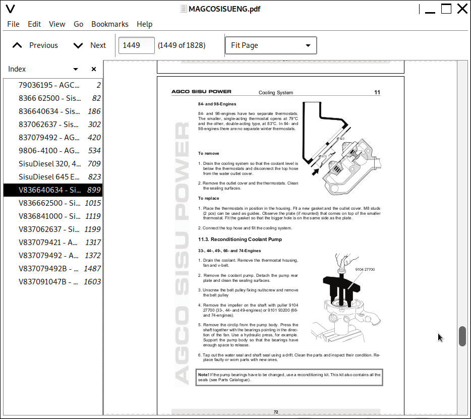
11.3 Reconditioning Coolant Pump...78
11.4 Coolant Pumps with Heavy Duty Bearings...80
11.5 Install the Cylinder Head Connection Part...82
12. INLET AND EXHAUST SYSTEM...83
12.1. Checking the Air Cleaner...83
12.2. Checking the Inlet and Exhaust Pipes...83
12.3. Checking the Turbocharger...84
12.4. Fitting the Turbocharger...85
12.5. Cooled EGR system...86
13. FUEL SYSTEM...89
13.1. Technical Data...90
13.2. Bleeding Fuel System...91
13.3. Measuring Fuel Feed Pressure...91
13.4. Inspecting Injectors...92
13.5. High-Pressure Pump...94
13.6. Rail...95
13.7. Fuel Quality Requirements...96
13.8. SCR system...97
14. EEM3 ENGINE CONTROL SYSTEM...101
14.1 Contstruction of the EEM4...101
14.2 EEM4 Engine Control System Desc...101
14.3 Service Tool of the EEM4 System...102
14.4 Changing the Control Unit (ECU)...103
14.5 Wiring Sets...104
14.6 Sensors of the Engine Control System...106
15. ELECTRICAL SYSTEM...109
15.1. Alternators...109
15.2. Starters...112
Sisu Fortius...1
CONTENTS...3
GENERAL...7
TO THE USER...7
SAFETY INSTRUCTIONS...8
ENGINE TYPE DESIGNATIONS...9
LOCATION OF THE ENGINE SERIAL NO...9
MARKING OF THE EEM 2 CONTROL UNIT...10
LIFTING THE ENGINE...10
CONSTRUCTION...11
Technical data...11
General...12
Cylinder block...12
Flywheel housing...12
Cylinder head...13
Valve mechanism...13
Crank mechanism...13
Timing gears...14
Lubricating system...15
Cooling system...16
Inlet and exhaust system...17
TECHNICAL DATA...18
Cylinder block...18
Cylinder block, 84-engines...18
Cylinder liners...18
Cylinder head...18
Valves, rockers and tappets...19
Camshaft...20
Crankshaft...20
Crankshaft, 84-engines...21
Flywheel...22
Balancing unit, 44-engines...22
Timing gears...22
Timing gears, 84-engines...23
Connecting rod...23
Piston, rings and pin...24
Piston, rings and pin, 84-engines...24
Lubricating system...25
Oil pump, 33- and 44-engines...25
Oil pump, 66-, 74- and 84-engines...26
Coolant pump, 33- and 44-engines...26
Coolant pump, 66- and 74-engines...26
Coolant pump, 84-engines...26
Thermostat...27
Turbocharger...27
TIGHTENING TORQUES...28
SPECIAL TOOLS...29
Cylinder block...29
Timing gear- and flywheel housing...30
Cylinder head and valve mechanism...31
Crank mechanism...32
Coolant pump...33
Fuel system...34
WORK INSTRUCTIONS...35
1. CYLINDER BLOCK...35
A. Measuring cylinder liner wear...35
B. Removing cylinder liner...35
C. Checking cylinder block...35
D. Changing camshaft bushing...35
E. Fitting plug at camshaft rear end...37
F. Oversize bushings for camshaft...37
G. Fitting plug at camshaft rear end (oversize bushings)...37
H. Fitting cylinder liner...38
2. FLYWHEEL HOUSING...41
A. Fitting flywheel housing...41
B. Changing crankshaft rear oil seal...41
3. CYLINDER HEAD...43
A. Removing cylinder head...43
B. Removing valves...43
C. Checking cylinder head...43
D. Changing valve guides...44
E. Machining valve seat...44
F. Changing valve seat rings...45
G. Grinding valves...45
H. Fitting valves...45
I. Fitting cylinder head...46
4. VALVE MECHANISM...47
A. Reconditioning valve mechanism...47
B. Changing camshaft / camshaft gear...47
C. Adjusting valves...48
5. CRANKSHAFT...51
A. Removing crankshaft...51
B. Checking crankshaft...51
C. Changing crankshaft gears...51
D. Fitting crankshaft...52
E. Crankshaft hub piece...53
F. Checking element of the rubber damper...53
G. Viscose type vibration damper...53
H. Changing crankshaft pulley / vibration damper...54
6. CONNECTING RODS AND PISTONS...55
A. Removing pistons together with connecting rods...55
B. Changing connecting rod bearings...55
C. Checking connecting rod...55
D. Changing piston rings...56
E. Checking pistons...57
F. Fitting piston pin...57
G. Fitting piston together with connecting rod...57
7. COUNTERBALANCE (44-engines)...59
A. Removing and disassembling counterbalance unit...59
B. Reconditioning counterbalance unit...59
C. Fitting counterbalance unit...59
D. Changing crankshaft gear rim...60
8. FLYWHEEL...61
A. Changing starter ring gear on flywheel...61
B. Fitting flywheel...61
9. TIMING GEAR ASSEMBLY...63
A. Removing timing gear casing...63
B. Reconditioning idler gear...63
C. Fitting timing gear casing...64
D. Idler gear with bevelled ball bearings...65
E. Power take-off...66
9. TIMING GEAR ASSEMBLY (84-engines)...67
A. Removing timing gear casing...67
B. Fitting timing gear casing...67
C. Fan drive device...69
10. LUBRICATION SYSTEM...71
A. Oil pressure regulating valve...71
B. Removing and dismantling lubricating oil pump...71
C. Assembling and fitting lubricating oil pump...71
D. Piston cooling nozzles...72
E. Fitting oil sump gasket...72
F. Lubricating oil cooler...72
G. Lubricating oil quality requirements...74
H. Oil capacities...74
11. COOLING SYSTEM...75
A. Quality requirements of coolant...75
B. Thermostat...75
C. Reconditioning coolant pump...76
D. Coolant pumps with heavy duty bearings...78
E. Reconditioning the coolant pump...78
12. INLET AND EXHAUST SYSTEM...79
A. Checking air cleaner...79
B. Checking inlet and exhaust pipes...79
C. Checking turbocharger...79
D. Fitting turbocharger...80
13. FUEL SYSTEM...81
Injectors...81
A. Removing injectors...82
B. Inspecting injectors...82
C. Reconditioning injectors...83
D. Fitting injector in engine...83
E. Fitting delivery pipes...84
Bosch VE rotary pump...85
Technical data...85
Fuel system, description...86
A. Bleeding the fuel system...87
B. Measuring the fuel feed pressure...87
C. Removing the fuel injection pump...87
D. Fitting the fuel injection pump...87
Bosch VP 30 and VP 44 rotary pump...89
Technical data...89
Fuel system, description...90
A. Bleeding fuel system...91
B. Measuring fuel feed pressure...91
C. Removing fuel injection pump...91
D. Fitting fuel injection pump...92
E. Fuel quality requirements...94
14. ENGINE CONTROL SYSTEM EEM 2...95
Construction of the EEM 2...95
EEM 2 Engine Control System, description...96
Service tool of EEM 2 system...96
A. Changing of Control Unit (ECU)...97
B. Sensors of Engine Control System...98
15. ELECTRICAL SYSTEM...99
A. Alternators...99
B. Starters...102
16. OPTIONAL EQUIPMENT...103
A. Compressor (Bendix)...103
B. Compressor (Knorr)...104
Introduction...IX
Purpose...IX
Scope...IX
Definitions, Terms, Acronyms and Abbreviations...IX
References...IX
EEM4 general instructions...XI
Fault Codes...XIII
SPN 100, FMI 1, Oil pressure LOW, ALARM...XIII
SPN 100, FMI 16, Oil pressure ABOVE NORMAL (>9,5bar/30?C)...XIV
SPN 100, FMI 18, Oil pressure LOW...XIV
SPN 100, FMI 3, Oil pressure sensor voltage above normal or open circuit...XV
SPN 100, FMI 31, Oil pressure sensor defect...XV
SPN 100, FMI 4, Oil pressure sensor voltage below normal...XVI
SPN 102, FMI 16, Boost pressure ABOVE NORMAL...XVI
SPN 102, FMI 18, Boost pressure LOW...XVII
SPN 102, FMI 3, Boost pressure sensor voltage above normal or open circuit...XVIII
SPN 102, FMI 31, Intake manifold pressure drop too HIGH at cranking...XVIII
SPN 102, FMI 4, Boost pressure sensor voltage below normal...XIX
SPN 1043, FMI 3, Internal 12V supply voltage above normal...XIX
SPN 1043, FMI 4, Internal 12V supply voltage below normal...XX
SPN 105, FMI 16, Intake air temp. ABOVE NORMAL (90?C)...XX
SPN 105, FMI 3, Intake air temp. sensor voltage above normal or open circuit...XX
SPN 105, FMI 4, Intake air temp sensor voltage below normal...I
SPN 1076, FMI 14, MPROP control, Open circuit...I
SPN 1076, FMI 3, MPROP control, High side short circuit to HIGH SOURCE...II
SPN 1076, FMI 4, MPROP control, Low side short circuit to GROUND...II
SPN 1076, FMI 5, MPROP control, Low side short circuit to HIGH SOURCE...III
SPN 1076, FMI 6, MPROP control, High side short circuit to GROUND...III
SPN 1077, FMI 3, MPROP control, Metering unit AD-channel voltage above normal...IV
SPN 1077, FMI 14, MPROP control, Powerstage over temperature...IV
SPN 1077, FMI 4, MPROP control, Metering unit AD-channel voltage below normal...V
SPN 107, FMI 18, Air filter pressure BELOW NORMAL...V
SPN 107, FMI 31, Air filter pressure sensor active at init state...V
SPN 108, FMI 3, Ambient pressure sensor voltage above normal or open circuit...VI
SPN 108, FMI 4, Ambient pressure sensor voltage below normal...VI
SPN 109, FMI 3, Coolant pressure sensor voltage above normal or open circuit...VII
SPN 109, FMI 4, Coolant pressure sensor voltage below normal...VII
SPN 110, FMI 0, Coolant temperature HIGH, ALARM (>113C)...VII
SPN 110, FMI 16, Coolant temperature ABOVE NORMAL (>106C)...VIII
SPN 110, FMI 3, Coolant temperature sensor voltage above normal or open circuit...IX
SPN 110, FMI 4, Coolant temperature sensor voltage below normal...IX
SPN 1136, FMI 0, ECU over temperature HIGH, ALARM...X
SPN 1136, FMI 3, ECU temperature sensor voltage above normal or open circuit...X
SPN 1136, FMI 4, ECU temperature sensor voltage below normal...XI
SPN 1321, FMI 3, Start relay high side voltage above normal...XI
SPN 1321, FMI 6, Start relay high side current above normal...XI
SPN 1485, FMI 11, ECU internal power off ERROR at previous afterrun...XII
SPN 1485, FMI 31, Main relay early opening at previous afterrun...XII
SPN 157, FMI 0, Rail pressure above normal...XIII
SPN 157, FMI 15, Rail pressure controller, Positive deviation...XIII
SPN 157, FMI 16, Rail pressure ABOVE NORMAL...XV
SPN 157, FMI 17, Rail pressure controller, Negative deviation...XV
SPN 157, FMI 18, Rail pressure below normal...XVI
SPN 157, FMI 2, Rail pressure raw value is intermittent...XVII
SPN 157, FMI 20, Rail pressure raw value is above maximum offset...XVIII
SPN 157, FMI 21, Rail pressure raw value is below minimum offset...XVIII
SPN 157, FMI 3, Rail pressure sensor voltage above normal or open circuit...XIX
SPN 157, FMI 31, Rail pressure, Leakage detected by quantity balance...XIX
SPN 157, FMI 4, Rail pressure sensor voltage below normal...XX
SPN 1639, FMI 18, Fan control underspeed or no signal detected...XXI
SPN 1639, FMI 19, Fan speed request CAN signal missing...XXI
SPN 168, FMI 0, Battery voltage ABOVE NORMAL...XXII
SPN 168, FMI 1, Battery voltage BELOW NORMAL (< 7,8 V)...XXII
SPN 168, FMI 3, Battery voltage sensor, voltage above normal...XXII
SPN 168, FMI 4, Battery voltage sensor, voltage below normal...XXIII
SPN 171, FMI 19, Ambient temperature CAN signal missing...XXIII
SPN 171, FMI 3, Ambient temperature sensor voltage above normal or open circuit...XXIII
SPN 171, FMI 4, Ambient temperature sensor voltage below normal...XXIV
SPN 174, FMI 0, Fuel inlet temperature HIGH, ALARM (>85?C)...XXIV
SPN 174, FMI 3, Fuel temperature sensor voltage above normal or open circuit...XXV
SPN 174, FMI 4, Fuel temperature sensor voltage below normal...XXV
SPN 1761, FMI 1, DEF tank EMPTY...XXVI
SPN 1761, FMI 18, DEF tank LEVEL LOW...XXVI
SPN 1761, FMI 3, DEF tank level sensor voltage above normal or open circuit...XXVI
SPN 1761, FMI 4, DEF tank level sensor voltage below normal...XXVII
SPN 2791, FMI 0, EGR Valve temperature alert...XXVII
SPN 2791, FMI 10, EGR Valve torque limited...XXVIII
SPN 2791, FMI 11, EGR Valve short cut...XXVIII
SPN 2791, FMI 12, EGR Valve initialization error...XXVIII
SPN 2791, FMI 14, EGR Valve overload...XXIX
SPN 2791, FMI 16, EGR Valve temperature warning...XXIX
SPN 2791, FMI 19, EGR Valve communication error...XXX
SPN 2791, FMI 31, EGR Valve not present...XXX
SPN 2791, FMI 7, EGR Valve position deviation...XXX
SPN 29, FMI 3, Throttle 2 sensor above normal or open circuit (IDLE)...XXXI
SPN 29, FMI 4, Throttle 2 sensor below normal (IDLE)...XXXI
SPN 3031, FMI 10, DEF tank temperature abnormal rate of change at heating cycle...XXXII
SPN 3031, FMI 14, DEF tank maximum defrost time exceeded...XXXII
SPN 3031, FMI 16, DEF tank temperature ABOVE normal...XXXIII
SPN 3031, FMI 3, DEF tank temp. sensor voltage above normal or open circuit...XXXIII
SPN 3031, FMI 4, DEF tank temp. sensor voltage below normal...XXXIV
SPN 3361, FMI 11, DEF dosing valve overheat protection...XXXIV
SPN 3361, FMI 14, DEF dosing valve current abnormal behaviour...XXXV
SPN 3361, FMI 3, DEF dosing valve low side short circuit to HIGH SOURCE...XXXV
SPN 3361, FMI 31, DEF dosing valve powerstage driver chip over temperature...XXXVI
SPN 3361, FMI 4, DEF dosing valve high side short circuit...XXXVI
SPN 3361, FMI 5, DEF dosing valve high side short circuit to HIGH SOURCE or open load...XXXVII
SPN 3361, FMI 6, DEF dosing valve low side short circuit to GROUND or open load...XXXVII
SPN 3363, FMI 3, DEF tank heater coolant valve solenoid short circuit to HIGH SOURCE...XXXVII
SPN 3363, FMI 31, DEF tank heater ECU power stage over temperature...XXXVIII
SPN 3363, FMI 4, DEF tank heater coolant valve solenoid short circuit to GROUND...XXXVIII
SPN 3363, FMI 5, DEF tank heater coolant valve solenoid open circuit...XXXIX
SPN 3509, FMI 31, 5Vdc Supply 1 voltage out of range...XXXIX
SPN 3510, FMI 31, 5Vdc Supply 2 voltage out of range...XL
SPN 3511, FMI 31, 5Vdc Supply 3 voltage out of range...XL
SPN 3512, FMI 3, 12V sensor supply 1 voltage above normal...XL
SPN 3512, FMI 4, 12V sensor supply 1 voltage below normal...XLI
SPN 3, FMI 14, Number of injections is limited by quantity balance of high pressure pump...XLI
SPN 4090, FMI 16, SCR system malfunction: NOx emission too HIGH...XLII
SPN 4090, FMI 18, SCR system malfunction: Measured NOx emission implausible...XLII
SPN 4201, FMI 2, Crank speed signal erratic, too much noise pulses...XLIII
SPN 4201, FMI 31, Crankshaft speed sensor signal missing...XLIII
SPN 4332, FMI 0, SCR system ERROR: DEF over pressure detected...XLIV
SPN 4332, FMI 11, SCR system ERROR: Pumped-Dosed quantities balance error...XLV
SPN 4332, FMI 14, SCR system ERROR: Pressure drop test failure...XLV
SPN 4332, FMI 16, SCR system ERROR: DEF dosing pressure above normal...XLVI
SPN 4332, FMI 18, SCR system ERROR: DEF dosing pressure below normal...XLVII
SPN 4332, FMI 31, SCR system ERROR: Emptying not completed at previous shutdown...XLVII
SPN 4334, FMI 3, DEF pressure sensor voltage above normal or open circuit...XLVIII
SPN 4334, FMI 4, DEF pressure sensor voltage below normal...XLVIII
SPN 4340, FMI 3, DEF suction line heater control circuit short circuit to HIGH SOURCE...XLIX
SPN 4340, FMI 31, DEF suction line heater ECU power stage over temperature...XLIX
SPN 4340, FMI 4, DEF suction line heater control circuit short circuit to GROUND...L
SPN 4340, FMI 5, DEF suction line heater control circuit open circuit...L
SPN 4342, FMI 3, DEF backflow line heater control circuit short circuit to HIGH SOURCE...L
SPN 4342, FMI 31, DEF backflow line heater ECU power stage over temperature...LI
SPN 4342, FMI 4, DEF backflow line heater control circuit short circuit to GROUND...LI
SPN 4342, FMI 5, DEF backflow line heater control circuit open circuit...LII
SPN 4344, FMI 12, DEF supply module temperature measurement module is not responding...LII
SPN 4344, FMI 2, DEF supply module heater temperature signal in invalid range...LII
SPN 4344, FMI 3, DEF supply module heater control circuit short circuit to HIGH SOURCE...LIII
SPN 4344, FMI 31, DEF supply module heater ECU power stage over temperature...LIII
SPN 4344, FMI 4, DEF supply module heater control circuit short circuit to GROUND...LIV
SPN 4344, FMI 8, DEF supply module heater temperature signal in failure range...LIV
SPN 4346, FMI 3, DEF pressure line heater control circuit short circuit to HIGH SOURCE...LV
SPN 4346, FMI 31, DEF pressure line heater ECU power stage over temperature...LV
SPN 4346, FMI 4, DEF pressure line heater control circuit short circuit to GROUND...LVI
SPN 4346, FMI 5, DEF pressure line heater control circuit open circuit...LVI
SPN 4354, FMI 3, DEF suction line heater relay low side (line relay) open circuit...LVI
SPN 4354, FMI 4, DEF suction line heater relay high side (heater, main relay) open circuit...LVII
SPN 4355, FMI 3, DEF backflow line heater relay low side (line relay) open circuit...LVII
SPN 4355, FMI 4, DEF backflow line heater relay high side (heater, main relay) open circuit...LVIII
SPN 4356, FMI 3, DEF supply module heater relay low side open circuit...LVIII
SPN 4356, FMI 4, DEF supply module heater relay high side (heater, main relay) open circuit...LIX
SPN 4356, FMI 5, DEF supply module heater relay open circuit...LIX
SPN 4357, FMI 3, DEF pressure line heater relay low side (line relay) open circuit...LIX
SPN 4357, FMI 4, DEF pressure line heater relay high side (heater, main relay) open circuit...LX
SPN 4360, FMI 2, SCR catalyst inlet gas temp sensor plausibility test FAILED...LX
!!! new_index = 81
!!! num_start = 1
!!! num_style = Arabic
SPN 4360, FMI 3, SCR catalyst inlet gas temp. sensor voltage above normal or open circuit...1
SPN 4360, FMI 4, SCR catalyst inlet gas temp. sensor voltage below normal...1
SPN 4363, FMI 2, SCR catalyst outlet gas temp sensor plausibility test FAILED...2
SPN 4363, FMI 3, SCR catalyst outlet gas temp. sensor voltage above normal or open circuit...2
SPN 4363, FMI 4, SCR catalyst outlet gas temp. sensor voltage below normal...3
SPN 4374, FMI 14, DEF pump motor speed permanent deviation...3
SPN 4374, FMI 31, DEF pump motor not available for actuation...4
SPN 4374, FMI 8, DEF pump motor speed deviation...4
SPN 4375, FMI 3, DEF pump motor control signal short circuit to HIGH SOURCE...4
SPN 4375, FMI 31, DEF pump motor control powerstage over temperature...5
SPN 4375, FMI 4, DEF pump motor control signal short circuit to GROUND...5
SPN 4375, FMI 5, DEF pump motor control signal current below normal or open circuit...6
SPN 4376, FMI 3, DEF pump direction valve low side short circuit to HIGH SOURCE...6
SPN 4376, FMI 31, DEF pump direction valve low side control powerstage over temperature...7
SPN 4376, FMI 4, DEF pump direction valve low side short circuit to GROUND...7
SPN 4376, FMI 5, DEF pump direction valve low side current below normal or open circuit...8
SPN 520200, FMI 16, Powerstages could be disabled due to high Battery voltage...8
SPN 520200, FMI 18, Powerstages could be disabled due to low Battery voltage...9
SPN 520201, FMI 19, Bus off Engine CAN (1M)...9
SPN 520202, FMI 3, ECU Main Relay 0 Short circuit to HIGH SOURCE...10
SPN 520202, FMI 4, ECU Main Relay 0 short circuit to GROUND...10
SPN 520203, FMI 3, ECU Main Relay 1 Short circuit to HIGH SOURCE...11
SPN 520203, FMI 4, ECU Main Relay 1 short circuit to GROUND...11
SPN 520204, FMI 3, ECU Main Relay 2 Short circuit to HIGH SOURCE...12
SPN 520204, FMI 4, ECU Main Relay 2 short circuit to GROUND...12
SPN 520205, FMI 31, Error in torque control input...12
SPN 520206, FMI 31, Chip error in the CY33x power stage component 1...13
SPN 520208, FMI 31, Rail PRV recognised as OPEN...13
SPN 520209, FMI 31, Error in the plausibility of the injection energizing time...14
SPN 520210, FMI 12, Error in the plausibility of the start of energising angles...14
SPN 520211, FMI 31, Chip error in the CY33x power stage component 0...15
SPN 520212, FMI 31, Diagnostic fault check to report the NTP error in ADC monitoring...15
SPN 520213, FMI 31, Diagnostic fault check to report the ADC test error...16
SPN 520214, FMI 31, Diagnostic fault check to report the error in Voltage ratio in ADC monitoring...16
SPN 520215, FMI 31, Diagnostic fault check to report errors in query-/response-communication...17
SPN 520216, FMI 31, Diagnostic fault check to report errors in SPI-communication...17
SPN 520217, FMI 31, Diagnostic fault check to report multiple error while checking the complete ROM-memory...17
SPN 520218, FMI 31, Loss of synchronization sending bytes to the MM from CPU...18
SPN 520219, FMI 31, DFC to set a torque limitation once an error is detected before MoCSOPs error reaction is set...18
SPN 520220, FMI 31, Wrong set response time...18
SPN 520221, FMI 31, Too many SPI errors during MoCSOP execution...19
SPN 520222, FMI 31, Diagnostic fault check to report the error in undervoltage monitoring...19
SPN 520223, FMI 31, Diagnostic fault check to report that WDA is not working correct...19
SPN 520224, FMI 31, OS timeout in the shut off path test. Failure setting the alarm task period...20
SPN 520225, FMI 31, Diagnostic fault check to report that the positive test failed...20
SPN 520226, FMI 31, Diagnostic fault check to report the timeout in the shut off path test...21
SPN 520227, FMI 31, Diagnostic fault check to report the error in overvoltage monitoring...21
SPN 520228, FMI 12, Cy320 Multiple Power Supply module SPI/COM-Error...21
SPN 520229, FMI 13, Fast A/D Converter calibration error...22
SPN 520230, FMI 31, Engine specification mismatch...22
SPN 520231, FMI 31, PTO input error...22
SPN 520232, FMI 31, Bad digital input configuration...23
SPN 520234, FMI 31, Diagnostic fault check to report ABE active due to undervoltage detection...23
SPN 520235, FMI 31, Diagnostic fault check to report ABE active due to overvoltage detection...23
SPN 520236, FMI 31, Diagnostic fault check to report WDA/ABE active due to unknown reason...24
SPN 520237, FMI 31, Customer fault 1 via digital input...24
SPN 520238, FMI 31, Customer fault 2 via digital input...24
SPN 520239, FMI 3, DEF dosing valve after cooler voltage above normal or short to HIGH SOURCE...24
SPN 520239, FMI 5, DEF dosing valve after cooler current below normal or open circuit...25
SPN 520239, FMI 6, DEF dosing valve after cooler current above normal or short to GROUND...25
SPN 520240, FMI 31, Injector bank 0 short circuit...26
SPN 520241, FMI 31, Injector bank 1 short circuit...26
SPN 520242, FMI 31, Injector bank 2 short circuit...27
SPN 520243, FMI 31, Rail PRV is forced to open; perform pressure increase...28
SPN 520244, FMI 31, Rail PRV is forced to open; perform pressure shock...28
SPN 520245, FMI 31, Rail PRV reached maxium allowed opening count...29
SPN 520246, FMI 31, Rail PRV reached maximun allowed open time...30
SPN 520247, FMI 31, Reported SPI and COM-Errors of a Cy146...30
SPN 520248, FMI 31, Reported SPI and COM-Errors of a Cy146...30
SPN 520249, FMI 31, Reported SPI and COM-Errors of a Cy146...31
SPN 520250, FMI 31, Reported SPI and COM-Errors of a Cy146...31
SPN 520251, FMI 31, Reported SPI and COM-Errors of a Cy146...31
SPN 521000, FMI 2, DEF pump temperature signal duty cycle in invalid range...32
SPN 521000, FMI 8, DEF pump temperature signal duty cycle in failure range...32
SPN 521001, FMI 3, DEF heater main relay circuit short circuit to HIGH SOURCE...32
SPN 521001, FMI 31, DEF heater main relay ECU power stage over temperature...33
SPN 521001, FMI 4, DEF heater main relay open circuit...33
SPN 521002, FMI 3, DEF pump direction valve high side short circuit to HIGH SOURCE...34
SPN 521002, FMI 31, DEF pump direction valve high side control powerstage over temperature...34
SPN 521002, FMI 4, DEF pump direction valve high side short circuit to GROUND...35
SPN 521002, FMI 5, DEF pump direction valve high side current below normal or open circuit...35
SPN 521003, FMI 3, DEF heater main relay control circuit short circuit to HIGH SOURCE...35
SPN 521003, FMI 4, DEF heater main relay control circuit short circuit to GROUND...36
SPN 521004, FMI 11, Downstream NOx sensor missing...36
SPN 521004, FMI 12, Downstream NOx sensor stability time exceeded...37
SPN 521004, FMI 2, Downstream NOx sensor plausibility test FAILED...37
SPN 521005, FMI 11, Upstream NOx sensor missing...38
SPN 521005, FMI 12, Upstream NOx sensor stability time exceeded...38
SPN 521005, FMI 2, Upstream NOx sensor plausibility test FAILED...39
SPN 521006, FMI 12, Nox conversion plausibility test FAILED...39
SPN 521007, FMI 10, SCR system ERROR: DEF backflow line blocked or implausible...40
SPN 521007, FMI 14, SCR system ERROR: DEF pressure line or dosing valve blocked...40
SPN 521007, FMI 31, SCR system ERROR: DEF pressure stabilisation failure...41
SPN 521008, FMI 0, SCR system ERROR: DEF pressure reduction failure...42
SPN 521008, FMI 1, SCR system ERROR: DEF pressure build up failure...42
SPN 521010, FMI 14, DEF tank heater coolant valve solenoid high side short circuit to HIGH SOURCE...43
SPN 521010, FMI 3, DEF tank heater coolant valve solenoid low side short circuit to HIGH SOURCE...43
SPN 521010, FMI 31, DEF tank heater coolant valve low side power stage over temperature...44
SPN 521010, FMI 4, DEF tank heater coolant valve solenoid high side short circuit to GROUND...44
SPN 521010, FMI 5, DEF tank heater coolant valve solenoid low side open circuit...45
SPN 521010, FMI 6, DEF tank heater coolant valve solenoid low side short circuit to GROUND...45
SPN 626, FMI 3, Grid heater relay voltage above normal or short to HIGH SOURCE...45
SPN 626, FMI 5, Grid heater relay current below normal or open circuit...46
SPN 626, FMI 6, Grid heater relay current above normal or short to GROUND...46
SPN 639, FMI 19, Bus off Vehicle CAN (250k)...47
SPN 651, FMI 14, Solenoid valve 1, Short circuit...47
SPN 651, FMI 5, Solenoid valve 1, Current below normal: Open circuit...48
SPN 651, FMI 6, Solenoid valve 1, Current above normal: Short circuit between cables...48
SPN 652, FMI 14, Solenoid valve 2, Short circuit...49
SPN 652, FMI 5, Solenoid valve 2, Current below normal: Open circuit...49
SPN 652, FMI 6, Solenoid valve 2, Current above normal: Short circuit between cables...50
SPN 653, FMI 14, Solenoid valve 3, Short circuit...50
SPN 653, FMI 5, Solenoid valve 3, Current below normal: Open circuit...51
SPN 653, FMI 6, Solenoid valve 3, Current above normal: Short circuit between cables...51
SPN 654, FMI 14, Solenoid valve 4, Short circuit...52
SPN 654, FMI 5, Solenoid valve 4, Current below normal: Open circuit...52
SPN 654, FMI 6, Solenoid valve 4, Current above normal: Short circuit between cables...53
SPN 655, FMI 14, Solenoid valve 5, Short circuit...54
SPN 655, FMI 5, Solenoid valve 5, Current below normal: Open circuit...54
SPN 655, FMI 6, Solenoid valve 5, Current above normal: Short circuit between cables...55
SPN 656, FMI 14, Solenoid valve 6, Short circuit...55
SPN 656, FMI 5, Solenoid valve 6, Current below normal: Open circuit...56
SPN 656, FMI 6, Solenoid valve 6, Current above normal: Short circuit between cables...56
SPN 657, FMI 14, Solenoid valve 7, Short circuit...57
SPN 657, FMI 5, Solenoid valve 7, Current below normal: Open circuit...57
SPN 657, FMI 6, Solenoid valve 7, Current above normal: Short circuit between cables...58
SPN 677, FMI 3, Start relay low side voltage above normal or short to HIGH SOURCE...58
SPN 677, FMI 5, Start relay current below normal or open circuit...58
SPN 677, FMI 3, Start relay low side current above normal...59
SPN 723, FMI 2, Number and/or position of the camshaft pulses implausible - disturbed signal...59
SPN 723, FMI 31, Cam speed sensor signal missing...60
SPN 723, FMI 8, Signal deviation between crankshaft and camshaft too large...61
SPN 729, FMI 3, Grid heater voltage above normal...61
SPN 729, FMI 4, Grid heater voltage below normal...62
SPN 84, FMI 3, Vechicle speed sensor short to HIGH SOURCE...62
SPN 84, FMI 4, Vechicle speed sensor short to GROUND...63
SPN 91, FMI 3, Throttle 1 sensor above normal or open circuit (IDLE)...63
SPN 91, FMI 4, Throttle 1 sensor below normal (IDLE)...63
SPN 94, FMI 16, Fuel main filter inlet pressure ABOVE NORMAL...64
SPN 94, FMI 18, Fuel main filter inlet pressure BELOW NORMAL...64
SPN 94, FMI 3, Fuel main filter inlet pressure sensor voltage above normal or open circuit...65
SPN 94, FMI 31, Fuel main filter inlet pressure ALARM, out of safe operating range...66
SPN 94, FMI 4, Fuel main filter inlet pressure sensor voltage below normal...66
SPN 974, FMI 3, Throttle 3 sensor above normal or open circuit (IDLE)...67
SPN 974, FMI 4, Throttle 3 sensor below normal (IDLE)...67
SPN 977, FMI 3, Fan control output short circuit to HIGH SOURCE...68
SPN 977, FMI 5, Fan control output open circuit...68
SPN 977, FMI 6, Fan control output current above normal...68
SPN 97, FMI 31, Water in fuel...69
Sensor details...71
Engine sensors overview...71
Oil pressure sensor...71
Coolant temperature sensor...72
Fuel pressure sensor...74
Fuel temperature sensor...75
Crankshaft speed sensor...77
Camshaft speed sensor...77
NOx sensor...78
Exhaust gas temperature sensor...78
Boost pressure sensor...79
Intake air temperature sensor...80
Rail pressure sensor...81
Coolant pressure sensor...83
Scr details...85
SCR system overview...85
Supply module...85
Dosing module...88
Engine electric system...89
Grid heater solenoid...89
Start Relay...89
4-cyl engine injector harness...90
6-cyl engine injector harness...90
7-cyl engine injector harness...90
Engine ECU power supply...90
ECU Replacement Procedure...95
![]()