
John Deere Electronic Fuel Injection Systems Component Technical Manual (CTM68)
Catalog:
Model:
Price: US$ 39.00
Complete Component Technical Manual (CTM) with Electrical Wiring Diagrams for John Deere Electronic Fuel Injection Systems (Bosch & Denso Controls), with all the technical information to maintain, diagnose, repair, and rebuild like professional mechanics.
ctm68 - John Deere Electronic Fuel Injection Systems Component Technical Manual.pdf
Total Pages: 356 pages
File Format: PDF (PC/Mac/Android/Kindle/iPhone/iPad; bookmarked, ToC, Searchable, Printable)
Language: English etc
ctm68 - Electronic Fuel Injection Systems
Component Technical Manual
Table of Contents
Foreword
Section : Electronic Fuel Injection Systems
Group 00: Safety
Handle Fluids Safely—Avoid Fires
Prevent Battery Explosions
Prepare for Emergencies
Handle Chemical Products Safely
Avoid High-Pressure Fluids
Prevent Machine Runaway
Park Machine Safely
Support Machine Properly
Wear Protective Clothing
Work in Clean Area
Service Machines Safely
Work In Ventilated Area
Illuminate Work Area Safely
Replace Safety Signs
Use Proper Lifting Equipment
Remove Paint Before Welding or Heating
Avoid Heating Near Pressurized Fluid Lines
Avoid Harmful Asbestos Dust
Practice Safe Maintenance
Use Proper Tools
Dispose of Waste Properly
Live With Safety
Group 02: General Information
About This Manual
Engine Controller Serial Number Plate
Injection Pump Serial Number Plate
Glossary of Terms
System Power Requirements
Engine Controller Environmental Restrictions
Electrical Concepts
Using a Digital Multimeter
Use of a Diagnostic Reader
Group 05: Fuel Injection System Components
Major System Components
Engine Controller
Robert Bosch Injection Pump/Actuator Assembly
Nippondenso Injection Pump/Actuator Assembly
Auxiliary Speed Sensor
Transient Voltage Protection Module (TVP)
Group 10: Basic System and Diagnostic Features
How the Electronically-Controlled Fuel Injection System Works
Self-Diagnosis and Back Up Features
Fault Lamp Operation
Governor Modes
Starting Control
Maximum Fuel Quantity Control
Smoke Control
Fuel Temperature Compensation
Fuel Flow/Throttle Output Signal
Auxiliary Speed Output Signal
Understanding the Throttle Options
Diagnostic Codes Operation
Using the Electronic Governor Tester—JT05829
Listing of Diagnostic Codes
Group 15: Robert Bosch Fuel System Connectors
Engine Controller Connector (X1)
Auxiliary Speed/Sensor Connector (X2)
Fuel Shut-Off Solenoid Connector (X11)
Actuator Connector (X12)
Fuel Temperature Sensor Connector (X13)
In-Line Connectors (X7, X8, X9, X10)
Service Connectors (X3, X4, X5, X6)
Using the Diagnostic Voltages Connector (X3)
Using the Diagnostic Reader Connector (X4)
Group 20: Nippondenso Fuel System Connectors
Engine Controller Connector (X1)
Auxiliary Speed Sensor Connector (X2)
Fuel Shut-Off Solenoid Connector (X10)
Actuator Connectors (X7, X9)
Fuel Temperature Sensor Connector (X8)
Service Connectors (X3, X4, X5)
Using the Diagnostic Voltages Connector (X3)
Using the Diagnostic Reader Connector (X4)
Group 25: Robert Bosch Fuel Injection System Diagnostic Procedures
How to Start Troubleshooting a Problem
Troubleshooting Tools Needed
Troubleshooting Suggestions
Initial Operational Checks
Symptom-Only Procedures
Diagnostic-Codes-Present Procedures
Code 11—Primary Analog Throttle Input Too High
Code 12—Primary Analog Throttle Input Too Low
Code 13—Secondary Analog Throttle Input Too High
Code 14—Secondary Analog Throttle Input Too Low
Code 32—Actuator Solenoid Circuit Fault
Code 34—Rack Position Error
Code 35—Rack Position Voltage Too High
Code 36—Rack Position Voltage Too Low
Code 37—Fuel Temperature Input Too High
Code 38—Fuel Temperature Input Too Low
Code 39—Primary Speed Input Error
Code 41—Start Signal Missing
Code 42—Engine Overspeed
Code 43—PWM (Throttle Input Erratic, Too Short or Too Long)
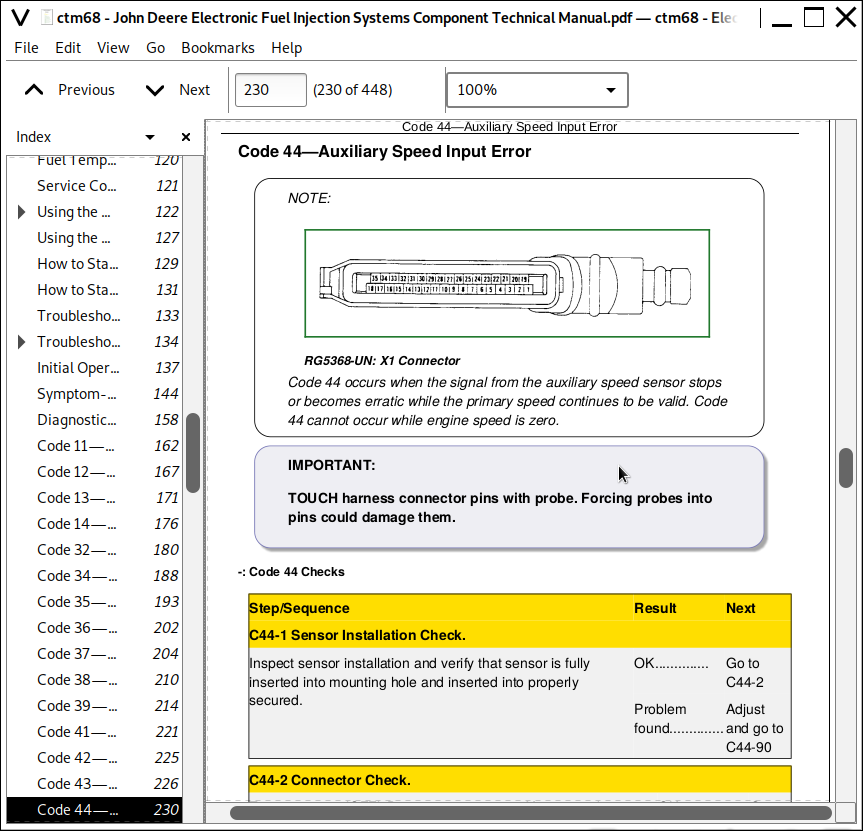
Code 44—Auxiliary Speed Input Error
Code 47—Derated Torque Curve Selected
Code 71—Diagnostic Codes Output Stuck High
Code 72—Diagnostic Codes Output Stuck Low
Code 73—Fuel Flow/Throttle Output Stuck High
Code 74—Fuel Flow/Throttle Output Stuck Low
Group 30: Robert Bosch Component Repairs and Adjustments
Analog Throttle Adjustments
Fuel Injection System Components
Essential Tools
Other Materials
Relieve System Pressure
Remove Fuel Shut-Off Solenoid Housing
Install Fuel Shut-Off Solenoid Housing
Remove and Replace Fuel Shut-Off Solenoid
Bleed the Fuel System
Engine Controller
Transient Voltage Protection (TVP) Module
Connectors
Clean Engine Controller Connector (X1)
Disassemble Engine Controller Connector (X1)
Remove Contact from Contact Housing
Install New Contacts
Reassemble Engine Controller Connector (X1)
Replace Fuel Shut-Off Solenoid Connector (X11)
Replace WEATHER PACK WEATHER PACK is a trademark of Packard Electric. Connector
Install WEATHER PACK WEATHER PACK is a trademark of Packard Electric. Contact
Sensors
Replace Fuel Temperature Sensor
Replace Auxiliary Speed Sensor
Group 35: Nippondenso Fuel Injection System Diagnostic Procedures
How To Start Troubleshooting a Problem
Troubleshooting Tools Needed
Troubleshooting Suggestions
Initial Operational Checks
Symptom-Only Procedures
Diagnostic-Codes-Present Procedures
Code 11—Primary Analog Throttle Input Too High
Code 12—Primary Analog Throttle Input Too Low
Code 13—Secondary Analog Throttle Input Too High
Code 14—Secondary Analog Throttle Input Too Low
Code 28—Engine Controller Failure
Code 29—Sensor Excitation Voltage Too High or Too Low
Code 33—Actuator Solenoid Output Shorted High
Code 34—Rack Position Error
Code 35—Rack Position Voltage Too High
Code 36—Rack Position Voltage Too Low
Code 37—Fuel Temperature Input Too High
Code 38—Fuel Temperature Input Too Low
Code 39—Primary Speed Input Error
Code 41—Start Signal Missing
Code 42—Engine Overspeed
Code 44—Auxiliary Speed Input Error
Code 47—Derated Torque Curve Selected
Code 51—Electrical Noise on Analog Throttle Input
Code 54—Electrical Noise on Rack Position Voltage Input
Code 55—Electrical Noise on Fuel Temperature Input
Code 56—Electrical Noise on Fuel Limit Select Input
Code 57—Electrical Noise on Speed Regulation Select Input
Code 58—Electrical Noise on 3-State Throttle Input
Code 59—Electrical Noise on Sensor +5V Supply
Code 71—Diagnostic Codes Output Stuck High
Code 72—Diagnostic Codes Output Stuck Low
Code 73—Fuel Flow/Throttle Output Stuck High
Code 74—Fuel Flow/Throttle Output Stuck Low
Group 40: Nippondenso Component Repairs and Adjustments
Analog Throttle Adjustments
Fuel Injection System Components
Essential Tools
Other Materials
Relieve System Pressure
Injection Pump/Actuator Assembly
Remove Fuel Shut-Off Solenoid Housing
Install Fuel Shut-Off Solenoid Housing
Replace Fuel Shut-Off Solenoid
Bleed Fuel System
Engine Controller
Transient Voltage Protection (TVP) Module
Connectors
Clean Engine Controller Connector (X1)
Disassemble Engine Controller Connector (X1)
Remove Contact From Housing
Install New Contacts
Reassemble Engine Controller Connector (X1)
Replace WEATHER PACK WEATHER PACK is a trademark of Packard Electric. Connector
Install WEATHER PACK WEATHER PACK is a trademark of Packard Electric. Contact
Sensors
Replace Fuel Temperature Sensor
Replace Auxiliary Speed Sensor
Group 45: Wiring
Robert Bosch—Wiring Harness
Robert Bosch Electronically-Controlled Fuel Injection System with Wiring Harnesses
Robert Bosch—System Wiring Schematic
Robert Bosch Connectors
Nippondenso Wiring Harness
Nippondenso Electronically-Controlled Fuel Injection System with Wiring Harness
Nippondenso System Wiring Schematic
Nippondenso Connectors
![]()