
John Deere PowerTech 8.1L Diesel Engines Level 9 Electronic Fuel System With Denso High Pressure Common Rail Component Technical Manual (CTM255)
JComplete Component Technical Manual with Electrical Wiring Diagrams for John Deere PowerTech 8.1L Diesel Engines Level 9 Electronic Fuel System With Denso High Pressure Common Rail, with all the technical information to maintain, diagnose, repair, and rebuild like professional mechanics.
John Deere PowerTech 8.1L Diesel Engines Level 9 Electronic Fuel System With Denso High Pressure Common Rail workshop service repair manual includes:
* Numbered table of contents easy to use so that you can find the information you need fast.
* Detailed sub-steps expand on repair procedure information
* Numbered instructions guide you through every repair procedure step by step.
* Troubleshooting and electrical service procedures are combined with detailed wiring diagrams for ease of use.
* Notes, cautions and warnings throughout each chapter pinpoint critical information.
* Bold figure number help you quickly match illustrations with instructions.
* Detailed illustrations, drawings and photos guide you through every procedure.
* Enlarged inset helps you identify and examine parts in detail.
ctm255 - PowerTech 8.1L Diesel Engines Level 9 Electronic Fuel System With Denso High Pressure Common Rail - (Worldwide Edition) Component Technical Manual.pdf
CTM255 (15FEB11) (ENGLISH) - John Deere PowerTech 8.1L Diesel Engines Level 9 Electronic Fuel System with Denso High Pressure Common Rail Component Technical Manual.pdf
ctm255 - PowerTechTM 8.1L Diesel Engines Level 9 Electronic Fuel System With Denso High Pressure Common Rail - (Worldwide Edition) Component Technical Manual.epub
Total Pages: 1,216 pages
File Format: PDF/EPUB/MOBI/AZW (PC/Mac/Android/Kindle/iPhone/iPad; bookmarked, ToC, Searchable, Printable)
Language: English
ctm255 - PowerTech™ 8.1L Diesel Engines Level 9 Electronic Fuel System With Denso High Pressure Common Rail -: (Worldwide Edition)
Component Technical Manual
John Deere PowerTech 8.1L Diesel Engines Level 9 Electronic Fuel System With Denso High Pressure Common Rail Component Technical Manual (CTM255)
Table of Contents
Foreword
Trademarks
Section 01: General
Group 000: Safety
Handle Fluids Safely—Avoid Fires
Handle Starting Fluid Safely
Service Cooling System Safely
Prevent Battery Explosions
Prepare for Emergencies
Handling Batteries Safely
Wait Before Opening High-Pressure Fuel System
Avoid High-Pressure Fluids
Wear Protective Clothing
Service Machines Safely
Protect Against Noise
Work In Ventilated Area
Work in Clean Area
Remove Paint Before Welding or Heating
Avoid Heating Near Pressurized Fluid Lines
Illuminate Work Area Safely
Use Proper Lifting Equipment
Construct Dealer-Made Tools Safely
Practice Safe Maintenance
Use Proper Tools
Decommissioning — Proper Recycling and Disposal of Fluids and Components
Live With Safety
Group 001: Engine Identification
Engine Model Designation
Engine Serial Number Plate Information
Engine Option Code Label
Group 002: Fuels, Lubricants, and Coolant
Lubricants and Coolant
Diesel Fuel - Tier 1
Diesel Fuel - Tier 2
Diesel Fuel Additive Products
Handling and Storing Diesel Fuel
Bio-Diesel Fuel
Testing Diesel Fuel
Fuel Filters
Lubricity of Diesel Fuel
Section 02: Repair and Adjustments
Group 090: Electronic Fuel System Repair and Adjustments
Fuel System - General Information
Relieve Fuel System Pressure
Clean Primary Fuel Filter (Strainer) (—246269)
Remove and Install Fuel Filter Head (—246269)
Remove and Install Fuel Filter Heads (246270—)
Fuel Filter Assemblies (—246269)
Fuel Filter Assemblies (246270—)
Replace Final Fuel Filter Element (—246269)
Replacing Fuel Filter Elements (246270—)
Remove and Install High Pressure Fuel Pump Overflow Valve
Remove and Install Hand Primer
Remove High-Pressure Fuel Pump
Remove and Install High Pressure Common Rail
Remove and Install Flow Limiters
Remove and Install HPCR Pressure Relief Valve
Install High-Pressure Fuel Pump
Remove Electronic Injectors
Clean Electronic Injector Bore
Clean Electronic Injector Orifice
Clean Electronic Injector Body
Inspect Electronic Injector Body
Install Electronic Injectors
Clean Electronic injectors (In Engine)
Group 110: Electronic Engine Control Repair and Adjustment
Engine Control Unit (ECU)
Electronic Engine Control System and Sensors
Fuel Pump Sensors
Replace Coolant Temperature Sensor
Replace Fuel Temperature Sensor
Replace Crankshaft Position Sensor
Replace Manifold Air Temperature (MAT) Sensor
Replace Water in Fuel (WIF) Sensor
Remove and Install Oil Pressure Sensor
Remove and Install Fuel Rail Pressure Sensor
Connectors
Use Electrical Insulating Compound
Using High-Pressure Washer
Repair WEATHERPACK Connector
Remove Blade Terminals from Connector Body
Repair (Pull Type) METRI-PACK™ Connectors
Repair (Push Type) METRI-PACK™ Connectors
Repair DEUTSCH Connectors
Repair AMP Connector
Repair SUMITOMO™ Connectors
Repair YAZAKI™ Connectors
Section 03: Theory Of Operation
Group 130: Electronic Fuel System Operation
About This Group
Fuel System Operation
Primary Fuel Filter (Strainer) Operation (—246269)
Primary Fuel Filter Operation (246270—)
Fuel Transfer Pump Operation
Final Fuel Filter Operation (—246269)
Final Fuel Filter Operation (246270—)
High Pressure Fuel Pump Operation
High Pressure Common Rail (HPCR) Operation
Electronic Injector (EI) Operation
Group 140: Electronic Control System Operation
About This Group
Electronic Control System Terminology
Electronic Control System Operation
Electronic Control System Overview
Monitoring Engine Parameters
Measuring Temperature
Measuring Pressure
Measuring Engine Speed
Water In Fuel (WIF) Sensor
Throttle Descriptions
Digital Throttle Adjustments
Marine Throttles
Pump Control Valves (PCVs)
Electronic Injector (EI) Wiring Harness Connector
Engine Control Unit (ECU)
Controlled Area Network (CAN)
Pilot Injection Operation
Low-Idle Warmup
Intake Air Heater Operation
Charge Air Cooling Operation
Cruise Control Operation
Engine Derate and Shutdown Protection
Torque Curves
Governor Droop Modes
Engine Control Unit (ECU) Self-Diagnosis
Section 04: Diagnostics
Group 150: Observable Diagnostics and Tests
About This Group
E1 - Engine Cranks/Won't Start/Very Hard to Start (—246269)
E1--Engine Cranks/Wont'Start/Very Hard to Start (246270--)
E2 - Engine Misfires/Runs Irregularly
E3 - Engine Does Not Develop Full Power
E4 - Engine Emits Excessive White Exhaust Smoke
E5 - Engine Emits Excessive Black or Gray Exhaust Smoke
E6 - Engine Will Not Crank
E7 - Engine Idles Poorly
E8 - Abnormal Engine Noise
F1 - Fuel Supply System Check
F2 - Excessive Fuel Consumption
F3 - Fuel in Oil
F4 - Excessive Fuel Filter Replacement
ECU Does Not Communicate with Service ADVISOR
D1 - ECU Does Not Communicate with DST
D2 - Diagnostic Gauge (Earlier Model) Does Not Communicate With ECU
D2 - Diagnostic Gauge (Earlier Model) Does Not Communicate With ECU
D3 - Diagnostic Gauge (Later Model) Does Not Communicate With ECU
D3 - Diagnostic Gauge (Later Model) Does Not Communicate With ECU
A1 - Intake Air Heater Check
A1 - Intake Air Heater Check
Mechanical Compression Test
Check Fuel Supply Quality
Test for Air in Fuel
Check Fuel Supply Pressure
Check for Restricted Fuel Return Line
Bleed the Fuel System (—246269)
Restarting Engine That Has Run Out Of Fuel (—246269)
Bleed the Fuel System (246270—)
Electric Fuel Priming Pump
Bleed the Fuel System Using Electric Priming Pump (246270—)
Restarting Engine That Has Run Out of Fuel (246270—)
Check and Adjust High Pressure Fuel Pump Static Timing
Load Profile Information Test — Instructions
Electrical Concepts
Using a Digital Multimeter
Electrical Circuit Malfunctions
Troubleshooting Circuit Malfunctions
Primary CAN Diagnostic Procedure
Terminal Test
Diagnostic Test Box — Using
Group 160: Trouble Code Diagnostics and Tests
About This Group
Connecting to Diagnostic Scan Tool (DST)
Connecting to Service ADVISOR
Viewing Active DTCs on Diagnostic Gauge (Earlier Model)
Viewing Stored DTCs on Diagnostic Gauge (Earlier Model)
Clearing Stored DTCs on Diagnostic Gauge (Earlier Model)
Engine Configuration Parameters on Diagnostic Gauge (Earlier Model)
Viewing Active DTCs on Diagnostic Gauge (Later Model)
Viewing Stored DTCs on Diagnostic Gauge (Later Model)
Clearing Stored DTCs on Diagnostic Gauge (Later Model)
Data Parameters on Diagnostic Tools
Engine Test Instructions—Cylinder Misfire Test
Engine Test Instructions—Compression Test
Engine Test Instructions— Cylinder Cutout Test
Engine Test Instructions— Tractor Torque Curve Change Test
Engine Control Unit (ECU) — Donating this Engine’s ECU to be Used Elsewhere
Engine Control Unit (ECU) — Replacing Current ECU with Another ECU
Engine Control Unit (ECU) — Replacing Current ECU with Another ECU — Cannot Communicate with Current ECU
Engine Control Unit (ECU) — Reprogramming Current ECU
Engine Control Unit (ECU) — Reprogramming Instructions
Diagnostic Trouble Codes (DTCs)
List of Diagnostic Trouble Codes (DTCs) on ECU
Diagnostic Procedure Overview
Intermittent Fault Diagnostics
T1 - Multi-state Throttle Input High
T2 - Multi-state Throttle Input Low
T3 - Analog Throttle (A) Input High
T4 - Analog Throttle (A) Input Low
T5 - Analog Throttle (B) Input High
T6 - Analog Throttle (B) Input Low
T7 - CAN Throttle Invalid
T8 - PWM Throttle Input High
T9 - PWM Throttle Input Low
T10 - PWM Throttle Abnormal Pulse Width
T11 - Excavator Throttle Reference Voltage High
T12 - Excavator Throttle Reference Voltage Low
T13 - Excavator Throttle Ground Voltage High
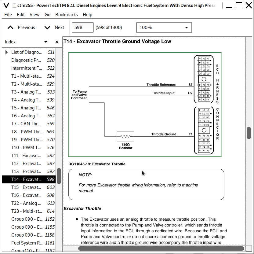
T14 - Excavator Throttle Ground Voltage Low
T15 - Excavator Throttle Input Voltage High
T16 - Excavator Throttle Input Voltage Low
T22 - Analog Throttle (A) Input Voltage Out of Range
T23 - Multi-state Throttle Input Voltage Out of Range
000028.03 - Throttle Voltage High
000028.04 - Throttle Voltage Low
000029.03 - Throttle Voltage High
000029.04 - Throttle Voltage Low
000029.14 - Throttle Voltage Out of Range
000084.09 - Vehicle Speed Invalid or Missing
000091.03 - Throttle Voltage High
000091.04 - Throttle Voltage Low
000091.08 - PWM Throttle Abnormal Pulse Width
000091.09 - Throttle Invalid
000091.14 - Throttle Voltage Out of Range
000094.03 - Fuel Rail Pressure Input Voltage High
000094.04 - Fuel Rail Pressure Input Voltage Low
000094.10 - Fuel Rail Pressure Loss Detected
000094.17 - Fuel Rail Pressure Not Developed
000097.00 - Water in Fuel Continuously Detected
000097.03 - Water in Fuel Input Voltage High
000097.04 - Water in Fuel Input Voltage Low
000097.16 - Water in Fuel Detected
000097.31 - Water in Fuel Detected
000100.01 - Engine Oil Pressure Extremely Low
000100.03 - Engine Oil Pressure Input Voltage High
000100.04 - Engine Oil Pressure Input Voltage Low
000100.16 - Engine Oil Pressure Above Normal
000100.18 - Engine Oil Pressure Moderately Low
000102.03 - Manifold Air Pressure Input Voltage High
000102.04 - Manifold Air Pressure Input Voltage Low
000105.03 - Manifold Air Temperature Input Voltage High
000105.04 - Manifold Air Temperature Input Voltage Low
000105.16 - Manifold Air Temperature Moderately High
000107.00 - Air Filter Restriction
000110.00 - Engine Coolant Temperature Extremely High
000110.03 - Engine Coolant Temperature Input Voltage High
000110.04 - Engine Coolant Temperature Input Voltage Low
000110.15 - Engine Coolant Temperature High Least Severe
000110.16 - Engine Coolant Temperature Moderately High
000110.31 - Engine Coolant Temperature High
000111.01 - Engine Coolant Level Low
000158.17 - ECU Power Down Error
000160.02 - Wheel Speed Input Noise
000171.03 - Ambient Air Temperature Input Voltage High
000171.04 - Ambient Air Temperature Input Voltage Low
000174.00 - Fuel Temperature High Most Severe
000174.03 - Fuel Temperature Input Voltage High
000174.04 - Fuel Temperature Input Voltage Low
000174.16 - Fuel Temperature High Moderately Severe
000189.00 - Engine Speed Derate
000190.00 - Engine Overspeed Extreme
000190.01 - Engine Overload Moderate
000190.16 - Engine Overspeed Moderate
000190.18 - Engine Overload Severe
000237.02 - Vehicle Identification Number Invalid
000237.13 - Vehicle Identification Option Code Invalid
000237.31 - Vehicle Model Number Invalid
000523.09 - Gear Selection Invalid
000596.31 - Cruise Control On/Off Inputs Shorted
000611.03 - Electronic Injector Wiring Shorted To Power Source
000611.04 - Electronic Injector Wiring Shorted To Ground
000620.03 - Sensor Supply 1 Voltage High
000620.04 - Sensor Supply 1 Voltage Low
000627.01 - Electronic Injector Supply Voltage Problem
000629.13 - ECU Error
000636.02 - Pump Position Sensor Input Noise
000636.08 - Pump Position Sensor Input Missing
000636.10 - Pump Position Sensor Input Pattern Error
000637.02 - Crankshaft Position Input Noise
000637.07 - Crankshaft Position/Pump Position Timing Moderately Out of Sync
000637.08 - Crankshaft Position Input Missing
000637.10 - Crankshaft Position Input Pattern Error
000639.13 - CAN Bus Error
000640.31 - Engine Shutdown - Vehicle Request
000644.02 - External Speed Command Input Erratic
000651.05 - Cylinder #1 EI Circuit Open
000651.06 - Cylinder #1 EI Circuit Shorted
000651.07 - Cylinder #1 EI Fuel Delivery Failure
000652.05 - Cylinder #2 EI Circuit Open
000652.06 - Cylinder #2 EI Circuit Shorted
000652.07 - Cylinder #2 EI Fuel Delivery Failure
000653.05 - Cylinder #3 EI Circuit Open
000653.06 - Cylinder #3 EI Circuit Shorted
000653.07 - Cylinder #3 EI Fuel Delivery Failure
000654.05 - Cylinder #4 EI Circuit Open
000654.06 - Cylinder #4 EI Circuit Shorted
000654.07 - Cylinder #4 EI Fuel Delivery Failure
000655.05 - Cylinder #5 EI Circuit Open
000655.06 - Cylinder #5 EI Circuit Shorted
000655.07 - Cylinder #5 EI Fuel Delivery Failure
000656.05 - Cylinder #6 EI Circuit Open
000656.06 - Cylinder #6 EI Circuit Shorted
000656.07 - Cylinder #6 EI Fuel Delivery Failure
000898.09 - Vehicle Speed or Torque Message Invalid
000970.31 - Engine Shutdown - Auxiliary Request
000971.31 - External Fuel Derate Switch Active
001069.09 - Tire Size Invalid
001069.31 - Tire Size Error
001079.03 - Sensor Supply 2 Voltage High
001079.04 - Sensor Supply 2 Voltage Low
001080.03 - Fuel Rail Pressure Sensor Supply Voltage High
001080.04 - Fuel Rail Pressure Sensor Supply Voltage Low
001109.31 - Engine Protection Shutdown Warning
001110.31 - Engine Protection Shutdown
001347.05 - Pump Control Valve #1 Error
001347.07 - Fuel Rail Pressure Incorrect
001347.10 - Pump Control Valve #1 Fuel Flow Not Detected
001348.05 - Pump Control Valve #2 Error
001348.10 - Pump Control Valve #2 Fuel Flow Not Detected
001568.02 - Torque Curve Selection Invalid
001568.09 - Torque Curve Selection Missing
001569.31 - Fuel Derate
001638.00 - Hydraulic Oil Temperature High Most Severe
001638.03 - Hydraulic Oil Temperature Sensor Above Normal
001638.04 - Hydraulic Oil Temperature Sensor Voltage Below Normal
001638.16 - Hydraulic Oil Temperature High
001639.01 - Fan Speed Input Missing
001639.16 - Fan Speed Higher Than Expected
001639.18 - Fan Speed Lower Than Expected
002005.09 - ACU Signal Missing
002049.09 - Cab Signal Missing
002071.09 - CCU Signal Missing
002580.03 - Brake Pressure Sensor Voltage Above Normal
002580.04 - Brake Pressure Sensor Voltage Below Normal
Section 05: Tools
Group 170: Electronic Fuel/Control System Repair Tools and Other Materials
Group 090 - Electronic Fuel System Repair and Adjustment Essential Tools
Fuel System Repair and Adjustment Other Materials
Group 110 - Electronic Engine Control Repair Tools
Control Repair and Adjustment Other Materials
Group 180: Diagnostic Service Tools
JDE81-4
JDG820
JDG886
JDG1705
JDG10460
JDG10461
JDG10466
JDG11233
JDG11263
JT01674A
JT05412
JT07306
JT07328
Section 06: Specifications
Group 200: Repair Specifications
Unified Inch Bolt and Screw Torque Values
Metric Bolt and Screw Torque Values
General OEM Engine Specifications
Fuel System Component Torque Specifications
Engine Sensor Torque Specifications
Group 210: Diagnostic Specifications
Fuel System Diagnostic Specifications
Application Specifications
Articulated Dump Truck - Derate Specifications
Articulated Dump Trucks - Torque Curve Selection
Articulated Dump Trucks - Governor Mode Selection
Articulated Dump Trucks - ECU Terminal Identification
Cane Harvester - Derate Specifications
Cane Harvester - ECU Terminal Identification
Combines - Derate Specifications
Combines - Torque Curve Selection
Combines - Governor Mode Selection
Combines - ECU Terminal Identification
Crawler (Forestry) - Derate Specifications
Crawler (Forestry) - Torque Curve Selection
Crawler (Forestry) - Governor Mode Selection
Crawler (Forestry) - ECU Terminal Identification
Excavators - Derate Specifications
Excavators - Torque Curve Selection
Excavators - Governor Mode Selection
Excavators - ECU Terminal Identification
850/950 Feller Bunchers, Forwarders, and Harvesters (Forestry) - Derate Specifications
850/950 Feller Bunchers, Forwarders, and Harvesters (Forestry) - Torque Curve Selection
850/950 Feller Bunchers, Forwarders, and Harvesters (Forestry) - Governor Mode Selection
850/950 Feller Bunchers, Forwarders, and Harvesters (Forestry) - ECU Terminal Identification
Grader - Derate Specifications
Grader - Torque Curve Selection
Grader - Governor Mode Selection
Grader - ECU Terminal Identification
Loader - Derate Specifications
Loader - Torque Curve Selection
Loader - Governor Mode Selection
Loader - ECU Terminal Identification
OEM Engines - Derate Specifications
OEM Engines - Torque Curve Selection
OEM Engines - Governor Mode Selection With OC03040 Software or Later
OEM Engines - Governor Mode Selection With OC03036 Software or Earlier
OEM Engines - ECU Terminal Identification
OEM Engines - ECU Terminal Identification - Continued
Electronic Control System Wiring Diagram
6081 OEM Application Instrument Panel/Engine Start Components Electrical Wiring Diagram
6081 OEM Application Instrument Panel/Engine Start Components Electrical Wiring Diagram - Continued
Self-Propelled Forage Harvester - Derate Specifications
Self-Propelled Forage Harvester - Torque Curve Selection
Self-Propelled Forage Harvester - Governor Mode Selection
Self-Propelled Forage Harvester - ECU Terminal Identification
Skidders (Forestry) - Derate Specifications
Skidders (Forestry) - Torque Curve Selection
Skidders (Forestry) - Governor Mode Selection
Skidders (Forestry) - ECU Terminal Identification
Sprayer - Derate Specifications
Sprayer - Torque Curve Selection
Sprayer - Governor Mode Selection
Sprayer - ECU Terminal Identification
Tractors - 7010 Series - Derate Specifications
Tractors - 7010 Series - Torque Curve Selection
Tractors - 7010 Series - Governor Mode Selection
Tractors - 7010 Series - ECU Terminal Identification
Tractors - 7020 Series - Derate Specifications
Tractors - 7020 Series - Torque Curve Selection
Tractors - 7020 Series - Governor Mode Selection
Tractors - 7020 Series - ECU Terminal Identification
Tractors - 8020 Series - Derate Specifications
Tractors - 8020 Series - Torque Curve Selection
Tractors - 8020 Series - Governor Mode Selection
Tractors - 8020 Series - ECU Terminal Identification
Tractors - 9120 Series - Derate Specifications
Tractors - 9120 Series - Torque Curve Selection
Tractors - 9120 Series - Governor Mode Selection
Tractors - 9120 Series - ECU Terminal Identification
6.8 L and 8.1 L OEM Application Electronic Control System Wiring Diagram
8.1L Marine Application Electronic Control System Wiring Diagram
6.8 L & 8.1 L OEM Application Instrument Panel/Engine Start Components Electrical Wiring Diagram
6.8 L & 8.1 L OEM Application Instrument Panel/Engine Start Components Electrical Wiring Diagram - Continued
![]()