
John Deere PowerTech 13.5L OEM Diesel Engines Base Engine Repair Component Technical Manual (CTM415)
Complete Base Engine Repair manual with Electrical Wiring Diagrams for John Deere PowerTech 13.5L OEM Diesel Engines Base Engine (Worldwide Edition), with all the technical information to maintain, diagnose, repair, and rebuild like professional mechanics.
John Deere PowerTech 13.5L OEM Diesel Engines Base Engine Repair Component Technical manual includes:
* Numbered table of contents easy to use so that you can find the information you need fast.
* Detailed sub-steps expand on repair procedure information
* Numbered instructions guide you through every repair procedure step by step.
* Troubleshooting and electrical service procedures are combined with detailed wiring diagrams for ease of use.
* Notes, cautions and warnings throughout each chapter pinpoint critical information.
* Bold figure number help you quickly match illustrations with instructions.
* Detailed illustrations, drawings and photos guide you through every procedure.
* Enlarged inset helps you identify and examine parts in detail.
ctm415 - John Deere PowerTech 13.5L OEM Diesel Engines Base Engine Repair - (Worldwide Edition) Component Technical Manual.pdf
ctm415 - John Deere PowerTech 13.5L OEM Diesel Engines Base Engine Repair - (Worldwide Edition) Component Technical Manual.epub
Total Pages: 814 pages
File Format: PDF/EPUB/MOBI/AZW (PC/Mac/Android/Kindle/iPhone/iPad; bookmarked, ToC, Searchable, Printable)
Language: English
ctm415 - PowerTech™ 13.5L OEM Diesel Engines Base Engine Repair -: (Worldwide Edition)
Component Technical Manual
Table of Contents
Foreword
PowerTech™ Plus 6135HF485 Engines
PowerTech™ E 6135HF475 Engines
6135 PowerTech™ Engine Cutaway View
6135 PowerTech™ Plus Engine Cutaway View
Section 01: General Information
Group 000: Safety
Avoid Heating Near Pressurized Fluid Lines
Avoid High-Pressure Fluids
Avoid Hot Exhaust
Avoid Static Electricity Risk When Refueling
Construct Dealer-Made Tools Safely
Decommissioning — Proper Recycling and Disposal of Fluids and Components
Follow Safety Instructions
Handle Agricultural Chemicals Safely
Handle Fluids Safely—Avoid Fires
Handling Batteries Safely
Illuminate Work Area Safely
Install All Guards
Live With Safety
Park Machine Safely
Practice Safe Maintenance
Precautions for Welding
Prepare for Emergencies
Prevent Acid Burns
Prevent Battery Explosions
Prevent Machine Runaway
Protect Against High Pressure Spray
Protect Against Noise
Recognize Safety Information
Remove Paint Before Welding or Heating
Replace Safety Signs
Service Cooling System Safely
Service Machines Safely
Stay Clear of Rotating Drivelines
Support Machine Properly
Understand Signal Words
Use Proper Lifting Equipment
Use Proper Tools
Use Steps and Handholds Correctly
Wait Before Opening High-Pressure Fuel System
Wear Protective Clothing
Work in Clean Area
Work In Ventilated Area
Group 001: Engine Identification and Applications
Engine Model Designation
Engine Serial Number Plate Information
Engine Option Code Label
Group 002: Fuels, Lubricants and Coolant
Diesel Fuel
Diesel Fuel Additive Products
BioDiesel Fuel
Minimizing the Effect of Cold Weather on Diesel Engines
Handling and Storing Diesel Fuel
Lubricity of Diesel Fuel
Testing Diesel Fuel
Fuel Filters
Engine Oil and Filter Service Intervals
Diesel Engine Oil — Tier 3 and Stage III
Diesel Engine Break-In Oil — Non-Emissions Certified and Certified Tier 1, Tier 2, Tier 3, Stage I, Stage II, and Stage III
Oil Filters
Grease
Alternative and Synthetic Lubricants
Lubricant Storage
Mixing of Lubricants
Diesel Engine Coolant (engine with wet sleeve cylinder liners)
Supplemental Coolant Additives
Operating in Warm Temperature Climates
Additional Information About Diesel Engine Coolants and John Deere LIQUID COOLANT CONDITIONER
Diesel Engine Coolant
Testing Diesel Engine Coolant
Drain Intervals for Diesel Engine Coolant
Section 02: Repair and Adjustments
Group 010: Engine Rebuild Guide, Break-In and Tune-Up
Engine Overhaul Guidelines
Engine Repair Stand
Safety Precautions
Disconnect Turbocharger Oil Inlet Line
Install Adapter on Repair Stand
Engine Lifting Procedure
Mount Engine on Repair Stand
Clean Engine
6135 Engine Disassembly Sequence
Sealant Application Guidelines
6135 Engine Assembly Sequence
Engine Break-In Guidelines
Perform Engine Break-In
Check Crankcase Ventilation System
Check Air Intake System
Check Exhaust System
Check and Service Cooling System
Check Electrical System
Group 020: Cylinder Head and Valves
Remove and Install Rocker Arm Cover
Clean and Inspect Crankcase Ventilation Assembly
Replace Rocker Arm Cover Gasket
Check and Adjust Valve Assembly Clearances and Injector Preload
Remove Rocker Arm Assembly
Remove Cylinder Head
Diagnosing Head Gasket Joint Failures
Head Gasket Inspection and Repair Sequence
Disassemble and Inspect Rocker Arms and Shaft Assembly
Preliminary Cylinder Head and Valve Checks
Assemble Rocker Arms and Shaft Assembly
Check Valve Height in Relation to Head Surface (Valve Recess)
Remove Valve Assembly
Inspect and Measure Valve Springs
Inspect Valve Rotators
Clean, Inspect, and Measure Valves
Grind Valves
Clean and Inspect Cylinder Head
Check Cylinder Head Flatness
Measure Cylinder Head Thickness
Measure Valve Guide ID
Replace Valve Guides
Clean and Inspect Valve Seats
Valve Seat — Grinding
Remove Valve Seat Inserts
Measure Valve Seat Bore in Cylinder Head
Install Valve Seat Inserts
Install Valves
Replace Unit Injector Sleeve in Cylinder Head Using JDG981
Replace Unit Injector Sleeve in Cylinder Head Using JDG1184
Remove Unit Injector Sleeve Using JDG10014
Clean and Inspect Top Deck of Cylinder Block
Measure Cylinder Liner Standout (Height Above Block)
Install Cylinder Head
Torque-Turn Cylinder Head Cap Screws
Install Rocker Arm Assembly
Complete Final Assembly for Cylinder Head Installation
Group 030: Cylinder Block, Liners, Pistons, and Rods
Remove and Install Cylinder Block Front Plate
Preliminary Liner, Piston, and Rod Checks
Connecting Rods—General Information
Remove Piston Spray Jets
Remove Pistons and Connecting Rods
Measure Cylinder Liner Standout (Height Above Block)
Remove Cylinder Liners Using D01062AA or D01073AA Cylinder Liner Puller
Remove Cylinder Liners Using JDG1145 Cylinder Liner Service Set
Visually Inspect Cylinder Liners
Deglaze Cylinder Liners
Clean Cylinder Liners
Cylinder Liner Manufacturing Date Code Explanation
Disassemble Piston/Rod Assembly and Clean Piston
Check Piston Oil Control Ring Groove Wear
Inspect Piston Pin and Pin Bore in Piston
Determine Piston-to-Liner Clearance
Measure Liner Flange Thickness
Inspect and Measure Connecting Rod Bearings
Inspect Connecting Rod and Cap
Inspect Piston Pins and Rod Bushings
Complete Disassembly of Cylinder Block (If Required)
Inspect and Clean Cylinder Block
Cylinder Block — Inspect and Reclaim
Cylinder Block — Measurements
Install Cylinder Liner Shim
Install Cylinder Liner O-Rings and Packings
Install Cylinder Liners
Assemble Pistons and Connecting Rods
Install Pistons and Connecting Rods
Torque-Turn Connecting Rod Cap Screws
Check Engine Rotation for Excessive Tightness
Install Piston Spray Jets
Measure Piston Protrusion
Complete Final Assembly
Group 040: Crankshaft, Main Bearings, and Flywheel
Crankshaft Rubber Damper Torque Sequence
Inspect Crankshaft Vibration Damper
Check Crankshaft End Play
Remove Crankshaft Rubber Damper and Pulley
Remove Viscous Damper and Front Crankshaft Oil Seal
Remove Timing Gear Cover
Check Flywheel Housing Face Runout
Check Flywheel Face Flatness
Remove Flywheel
Inspect and Repair Flywheel
Replace Flywheel Ring Gear
Remove and Install Flywheel Housing
Install Flywheel
Remove Rear Crankshaft Oil Seal and Housing Assembly
Crankshaft Unitized Rear Oil Seal — Removal
Crankshaft Unitized Rear Oil Seal and Housing — Installation
Crankshaft and Main Bearing Failure Analysis
Remove Crankshaft Main Bearings
Check Main Bearing-to-Journal Oil Clearance
Remove Crankshaft
Inspect Crankshaft
Measure Assembled ID of Bearings and OD of Crankshaft Journals
Measure Assembled ID of Main Bearing Caps (Without Bearings)
Replace Crankshaft Drive Gear
Inspect Thrust Bearings
Thrust Bearing New Part Specifications
Install Main and Thrust Bearing Inserts in Block
Install Crankshaft
Install Crankshaft Rear Oil Seal Housing
Install Crankshaft Rear Oil Seal and Wear Sleeve Assembly
Install Timing Gear Cover
Install Crankshaft Rubber Damper and Front Oil Seal
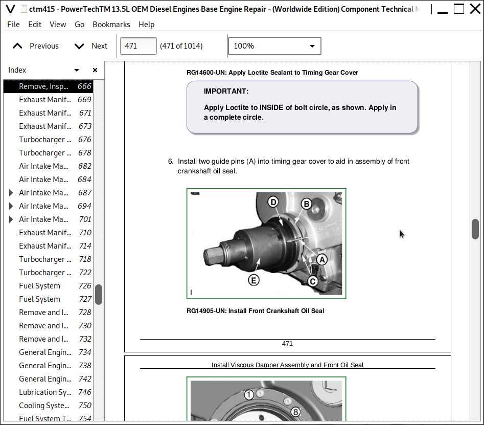
Install Viscous Damper Assembly and Front Oil Seal
Complete Final Assembly
Group 050: Camshaft and Timing Gear Train
Camshaft Timing Pin
Check and Adjust Camshaft-to-Crankshaft Timing
Adjust Front Timing Gear Backlash Using JDG993
Adjust Front Timing Gear Backlash Without Using JDG993
Remove and Install Camshaft
Replace Fuel Supply Pump Drive Pin
Visually Inspect Camshaft and Roller Followers
Inspect and Measure Camshaft Bushing ID and Journal OD
Measure Camshaft Lobe Lift Height
Inspect Camshaft Position Sensor Lobe
Replace Camshaft Bushings
SAE “A” (Front) and SAE “B” (Rear) Auxiliary Drive Assembly
SAE B Rear Auxiliary Drive — Removal and Installation
Align SAE “A” Front Auxiliary Drive Adapter
Group 060: Lubrication System
Oil Filter and Oil Conditioning Housing Assembly
Remove Oil Filter and Valve Housing/Oil Cooler Cover and Valve Housing
Inspect and Replace Oil Filter Adapter
Remove, Inspect, and Install Oil Pressure Regulating Valve
Remove, Inspect, and Install Oil Cooler and Oil Filter Bypass Valves
Remove, Inspect, and Install Oil Pressure Relief Valve
Remove, Clean, and Inspect Engine Oil Cooler
Install Oil Cooler/Oil Filter Valve Housing Assembly or Oil Cooler Cover/Valve Housing Assembly
Remove Engine Oil Pump
Clean and Inspect Oil Pump and Drive Gear
Install Engine Oil Pump
Remove Engine Oil Pan
Remove and Install Oil Pickup Tube
Install Engine Oil Pan
Oil Dipstick Tube Assembly — Installation
Oil Dipstick Tube Assembly — Removal
Group 070: Cooling System
Replace Bearings in Fan Drive Assembly
Inspect and Check Belt Tensioner Spring Tension
Replace Belt Tensioner Assembly
Remove Coolant Pump
Clean and Inspect Coolant Pump Parts
Install Coolant Pump
Remove and Install Thermostat Cover and Thermostats
Test Thermostat Opening Temperature
Remove and Install Thermostat Housing and Coolant Tubes
Remove and Install Coolant Heater—if Equipped
Bleed Air from Coolant System
Group 080: Air Intake and Exhaust System
Extending Turbocharger Life
Remove and Install Variable Geometry Turbocharger Actuator
Remove and Install Actuator Linkage
Remove Turbocharger
Turbocharger — Failure Analysis
Turbocharger Seven-Step Inspection
Perform Radial Bearing Clearance Test
Turbocharger — Repair
Prelube Turbocharger
Install Turbocharger
Turbocharger Break-In
Recommendations for Turbocharger Use
Remove, Inspect, and Install EGR Cooler
Exhaust Manifold — Remove
Exhaust Manifold — Install
Remove, Inspect, and Install Intake Manifold
Remove, Inspect, and Install EGR Valve (Tier 3/Stage III A)
Group 081: Air Intake and Exhaust System — PowerTech™ E Engines
Exhaust Manifold — Remove
Exhaust Manifold — Install
Turbocharger — Remove
Turbocharger — Install
Air Intake Manifold — Remove
Air Intake Manifold — Install
Group 082: Air Intake and Exhaust System — Marine Engines
Air Intake Manifold (Marine) — Removal
Air Intake Manifold (Marine) — Installation
Exhaust Manifold (Marine) — Removal
Exhaust Manifold (Marine) — Installation
Turbocharger (Marine) — Removal
Turbocharger (Marine) — Installation
Group 090: Fuel System
Fuel System
Group 100: Starting and Charging Systems
Remove and Install Alternator (OEM Engines)
Remove and Install Starter Motor (OEM Engines)
Section 03: Theory of Operation
Group 120: Base Engine Operation — PowerTech Plus
General Engine Operation
Lubrication System Operation
Cooling System Operation
Fuel System Theory of Operation
Head Gasket Joint Construction and Operation
Intake and Exhaust System Operation
Exhaust Gas Recirculator (EGR) & Variable Geometry Turbocharger (VGT) Operation
Turbocharger Operation
How the Turbocharger is Lubricated
Group 121: Base Engine Operation — PowerTech & PowerTech E
General Engine Operation
Lubrication System Operation
Cooling System Operation
Fuel System Theory of Operation
Head Gasket Joint Construction and Operation
Intake and Exhaust System Operation
Turbocharger Operation
How the Turbocharger is Lubricated
Section 04: Diagnostics
Group 150: Observable Diagnostics and Tests
About this Section of the Manual
13.5L - L1 - Excessive Oil Consumption
13.5L - L2 Engine Oil Pressure High
13.5L - L3 - Engine Oil Pressure Low
13.5L - L4 - Fuel in Oil
13.5L - L5 - Soot or Sludge in the Oil
13.5L - C1 - Engine Coolant Temperature Above Normal
13.5L - C2 - Engine Coolant Temperature Below Normal
13.5L Engines - C3 - Coolant in Oil or Oil in Coolant
13.5L Engines - C4 - Coolant Leaking from Weep Hole
Dynamometer Test
Check Cylinder Compression
Engine Oil Consumption
Check Engine Oil Pressure
Check for Excessive Engine Crankcase Pressure (Blow-By) (Base Pressure)
Check for Turbocharger Oil Seal Leak
Inspect Thermostat and Test Opening Temperature
Cooling System Pressure Test
Charge Air Cooler Test
Check for Head Gasket Failures
Check Intake Manifold Pressure (Turbo Boost)
Check Intake Manifold Pressure (Turbo Boost) — Fix Geometry Turbocharger
Check for Intake and Exhaust Restrictions
Check for Intake Air Leaks
Check for Exhaust Air Leaks
Check Camshaft-to-Crankshaft Timing
Check Crankshaft Position Sensor Depth
Check Engine Cranking Speed
EGR Cooler Test
Excessive Engine Vibration
Section 05: Tools and Other Materials
Group 170: Special Tools
75240
D01062AA
D01168AA
D01200AA
D01218AA
D01300AA
D05012ST-A
D05104ST
D05223ST
D01073AA
D17006BR
D17015BR
D17024BR
D17525CI
D17526CI
D17527CI
DFRG3
DFRG4
DFRG9
DFRG11
JDE41296
JDG164A
JDG451
JDG782A
JDG820
JDG839
JDG967
JDG968
JDG969A
JDG970B
JDG971
JDG972
JDG973
JDG974A
JDG975
JDG976
JDG977
JDG978
JDG981
JDG981-1
JDG982A
JDG993
JDG996
JDG1020
JDG1069
JDG1144
JDG1145
JDG1167
JDG1184
JDG1333
JDG1334
JDG1847
JDG10014
JDG10194
JDG10199
JDG10200
JDG10246A
JDG10249
JDG10357B
JDG10539A
JDG10668
JDG10996
JDG10997
JDG11008
JDG11056
JDG11084
JDG11334P3
JDG11373
JDG11374
JDG11544
JDG11831
JDG11860
JDG11864
JT01674A
JT05412
JT05697A
JT05993
JT07336
Group 180: Lubricants, Sealants, and Other Materials
Other Materials
Section 06: Specifications
Group 200: Repair and General OEM Specifications
General OEM Engine Specifications
Unified Inch Bolt and Screw Torque Values
Metric Bolt and Screw Torque Values
Engine Rebuild Guide, Break-In and Tune-Up (Group 010) Specifications
Cylinder Head and Valves (Group 020) Specifications
Cylinder Block, Liners, Pistons and Rods (Group 030) Specifications
Crankshaft, Main Bearings and Flywheel (Group 040) Specifications
Camshaft and Timing Gear Train (Group 050) Specifications
Lubrication System (Group 060) Specifications
Cooling System (Group 070) Specifications
Air Intake and Exhaust System (Group 080) Specifications — Variable Geometry Turbocharger
Air Intake and Exhaust System (Group 081) Specifications — Fixed Geometry Turbocharger
Starting and Charging Systems (Group 100) Specifications
Group 210: Diagnostic Specifications
Observable Diagnostics and Test Specifications
Dynamometer Test Specifications (OEM Engines)
Intake Manifold Pressure (Turbocharger Boost) Specifications
John Deere PowerTech 13.5L OEM Diesel Engines Base Engine Repair Component Technical Manual (CTM415)
![]()