
John Deere 3029, 4039, 4045, 6059, 6068 Engines Component Technical Manual (CTM3274)
Complete service repair manual with Electrical Wiring Diagrams for John Deere 3029, 4039, 4045, 6059, 6068 Diesel Engines, with all the technical information to maintain, diagnose, repair, and rebuild like professional mechanics.
John Deere 3029, 4039, 4045, 6059, 6068 Engines workshop service repair manual includes:
* Numbered table of contents easy to use so that you can find the information you need fast.
* Detailed sub-steps expand on repair procedure information
* Numbered instructions guide you through every repair procedure step by step.
* Troubleshooting and electrical service procedures are combined with detailed wiring diagrams for ease of use.
* Notes, cautions and warnings throughout each chapter pinpoint critical information.
* Bold figure number help you quickly match illustrations with instructions.
* Detailed illustrations, drawings and photos guide you through every procedure.
* Enlarged inset helps you identify and examine parts in detail.
ctm3274 - John Deere 3029, 4039, 4045, 6059, 6068 engines (saran) ( -499999cd) Component Technical Manual.pdf
ctm3274 - John Deere 3029, 4039, 4045, 6059, 6068 engines (saran) ( -499999cd) Component Technical Manual.epub
Total Pages: 603 pages
File Format: PDF/EPUB/MOBI/AZW (PC/Mac/Android/Kindle/iPhone/iPad; bookmarked, ToC, Searchable, Printable)
Language: English
Engine Application Chart
|
3000-SERIES TRACTORS |
ENGINE MODEL |
SERIAL NUMBER |
|---|---|---|
|
3100.............. |
CD3029DRT65 |
(189846 - ) |
|
3110.............. |
CD3029DRT65 |
|
|
3200/3200X.............. |
CD4039DRT35 |
(181345 - ) |
|
3210/3210X.............. |
CD4039DRT35 |
|
|
3300/3300X.............. |
CD4045DRT35 |
(182145 - ) |
|
3310/3310X.............. |
CD4045DRT35 |
|
|
3400/3400X.............. |
CD4039TRT35 |
(181775 - ) |
|
3410/3410X.............. |
CD4039TRT35 |
|
|
4000-SERIES TELESCOPIC HANDLERS |
ENGINE MODEL |
SERIAL NUMBER |
|---|---|---|
|
4400.............. |
CD4039TF005 |
(237697 - ) |
|
4500.............. |
CD4039TF005 |
|
|
5000-SERIES TRACTORS (Agritalia-built) |
ENGINE MODEL |
SERIAL NUMBER |
|---|---|---|
|
5300/5300N.............. |
CD3029DAT01 |
(315424 - ) |
|
5400/5400N.............. |
CD3029TAT02 |
(289398 - ) |
|
5500/5500N.............. |
CD4039TAT01 |
(346168 - ) |
|
5000-SERIES TRACTORS (Augusta-built) |
ENGINE MODEL |
SERIAL NUMBER |
|---|---|---|
|
5400N.............. |
CD3029TLV01 |
|
|
5500N.............. |
CD4039TLV01 |
(201353 - ) |
|
5000-SERIES TRACTORS (For India) |
ENGINE MODEL |
SERIAL NUMBER |
|---|---|---|
|
5300.............. |
CD3029DPY01 |
(383283 - ) |
|
6000-SERIES TRACTORS |
ENGINE MODEL |
SERIAL NUMBER |
|---|---|---|
|
6100 (Direct fan drive).............. |
CD4045DL001 |
(101582 - ) |
|
6100 (Viscous fan drive).............. |
CD4045DL002 |
(101582 - ) |
|
6200 (Direct fan drive).............. |
CD4039TL001 |
(101625 - ) |
|
6200 (Viscous fan drive).............. |
CD4039TL004 |
(101625 - ) |
|
6300 (Direct fan drive).............. |
CD4039TL003 |
(101649 - ) |
|
6300 (Viscous fan drive).............. |
CD4039TL006 |
(101649 - ) |
|
6400 (Direct fan drive).............. |
CD4045TL001 |
(101682 - ) |
|
6400 (Viscous fan drive).............. |
CD4045TL003 |
(101682 - ) |
|
6506 (Viscous fan drive).............. |
CD6068DL001 |
(214852 - ) |
|
6600 (Viscous fan drive).............. |
CD6059TL001 |
(128886 - ) |
|
6800 (Viscous fan drive).............. |
CD6068TL001 |
(124505 - ) |
|
6900 (Viscous fan drive).............. |
CD6068TL002 |
(186326 - ) |
|
WATERLOO TRACTORS |
ENGINE MODEL |
SERIAL NUMBER |
|---|---|---|
|
7600.............. |
T06068TRW01 |
|
|
ZWEIBRÜCKEN COMBINES |
ENGINE MODEL |
SERIAL NUMBER |
|---|---|---|
|
2054.............. |
6068HZ001 |
(116452 - ) |
|
2254.............. |
6068HZ001 |
|
|
ENGINES FOR CHINESE COMBINES |
SERIAL NUMBER |
|---|---|
|
CD6059TYC01.............. |
(367019 - ) |
|
CD6059TYC02.............. |
(363170 - ) |
|
ENGINES FOR GOLDONI TRACTORS |
SERIAL NUMBER |
|---|---|
|
CD3029DFG21.............. |
(287123 - ) |
|
CD3029DFG22.............. |
(287325 - ) |
|
CD3029TFG21.............. |
(287526 - ) |
|
SARAN OEM ENGINES |
SERIAL NUMBER |
SARAN OEM ENGINES |
SERIAL NUMBER |
|---|---|---|---|
|
CD3029DF |
CD3029TF |
||
|
CD3029DF001 |
CD3029TF001 |
||
|
CD3029DF005 |
(162670 - ) |
CD3029TF002 |
(170797 - ) |
|
CD3029DF031 |
CD3029TF031 |
||
|
CD3029DF032 |
CD3029TF032 |
(176015 - ) |
|
|
CD3029DF033 |
(177875 - ) |
CD3029TF033 |
(177880 - ) |
|
CD3029DF034 |
CD3029TF120 |
||
|
CD3029DF120 |
CD3029TF121 |
||
|
CD3029DF121 |
CD3029TF123 |
(354029 - ) |
|
|
CD3029DF122 |
(263024 - ) |
CD3029TF160 |
|
|
CD3029DF123 |
(312932 - ) |
CD3029TF161 |
(288419 - ) |
|
CD3029DF124 |
(340207 - ) |
CD3029TF162 |
|
|
CD3029DF128 |
CD3029TF163 |
(342829 - ) |
|
|
CD3029DF160 |
|||
|
CD3029DF161 |
(288417 - ) |
||
|
CD3029DF162 |
|||
|
CD3029DF163 |
|||
|
CD3029DF164 |
|||
|
CD3029DF165 |
|||
|
CD4039DF |
CD4039TF |
||
|
CD4039DF001 |
CD4039TF001 |
||
|
CD4039DF002 |
CD4039TF002 |
||
|
CD4039DF004 |
(152613 - ) |
CD4039TF003 |
(169516 - ) |
|
CD4039DF005 |
(165009 - ) |
CD4039TF004 |
(152616 - ) |
|
CD4039DF006 |
(340212 - ) |
CD4039TF005 |
|
|
CD4039DF007 |
(378895 - ) |
CD4039TF006 |
(339780 - ) |
|
CD4039DF008 |
CD4039TF007 |
(379066 - ) |
|
|
CD4039DF031 |
CD4039TF008 |
||
|
CD4039DF032 |
CD4039TF031 |
||
|
CD4039TF032 |
(166826 - ) |
||
|
CD4045DF001 |
CD4045TF001 |
||
|
CD4045DF031 |
CD4045TF002 |
(170081 - ) |
|
|
CD4045TF003 |
(342250 - ) |
||
|
CD4045TF008 |
|||
|
CD4045TF031 |
|||
|
CD6059DF |
CD6059TF |
||
|
CD6059DF001 |
CD6059TF001 |
||
|
CD6059DF002 |
CD6059TF002 |
(158390 - ) |
|
|
CD6059DF003 |
CD6059TF003 |
(158394 - ) |
|
|
CD6059TF004 |
|||
|
CD6059TF005 |
(166159 - ) |
||
|
CD6059TF006 |
(166960 - ) |
||
|
CD6059TF008 |
(341217 - ) |
||
|
CD6068DF001 |
CD6068TF001 |
||
|
CD6068TF002 |
(187378 - ) |
||
|
CD6068TF003 |
|||
|
CD6068TF004 |
(344260 - ) |
||
|
CD6068TF008 |
|||
|
CD6068TF009 |
ctm3274 - 3029, 4039, 4045, 6059, 6068 engines (saran) ( -499999cd)
Component Technical Manual
Table of Contents
Foreword
Engine Identification Views
Section MISC: Engine Application Chart
Group : Engine Application Chart
Engine Application Chart
Section : Safety
Group 00: Safety
Handle Fluids Safely-Avoid Fires
Prevent Battery Explosions
Prepare for Emergencies
Prevent Acid Burns
Avoid High-Pressure Fluids
Wear Protective Clothing
Service Machines Safely
Work in Ventilated Area
Work in Clean Area
Remove Paint Before Welding or Heating
Avoid Heating Near Pressurized Fluid Lines
Illuminate Work Area Safely
Use Proper Lifting Equipment
Practice Safe Maintenance
Use Proper Tools
Dispose of Waste Properly
Live With Safety
Group 01: General Information
Engine Identification
Engine Plate Information (Earlier Design)
Engine Plate Information (Later Design)
Repower Engine Plate
OEM Engine Option Code Label
Engine References
Basic Engine Specifications (3029 - 4039 & 6059)
Basic Engine Specifications (4045 & 6068)
Diesel Fuel
Diesel Engine Oil
Diesel Engine Coolant
Metric Bolt and Cap Screw Torque Values
Unified Inch Bolt and Cap Screw Torque Values
Group 02: Engine Mounting
Engine Repair Stand
Safety Precautions
Engine Lifting Procedure
Clean Engine
Disconnect Turbocharger Oil Inlet Line
Group 03: Engine Rebuild Guide
Engine Disassembly Sequence
Sealant Application Guidelines
Engine Assembly Sequence
Group 05: Cylinder Head and Valves
Special or Essential Tools
Specifications
Torques for Hardware
Cylinder Head - Exploded View
Check Valve Lift
Removing Cylinder Head
Cleaning Injection Nozzle Bores
Valve Actuating Parts
Remove Valves and Valve Springs
Checking Cylinder Head Flatness
Cleaning Valve Seats
Cleaning Valve Guides
Measure Valve Guides
Lapping Valve Seats
Check Valve Recess
Remove Valve Seat Inserts
Valve Seat Insert Installation
Check Valves
Grind Valves
Check Valve Spring Tension
Inspect Valve Rotators
Install Valves
Install Cylinder Head
Torque Turn Tightening Method
Checking Rocker Arm Shaft
Install Rocker Arm Assembly
Valve Clearance
Valve Adjustment Sequence
Install Rocker Arm Cover
Final Work
Group 10: Cyl. Block, Liners, Pistons & Rods
Special or Essential Tools
Specifications
Torques for Hardware
Exploded View
Piston and Connecting Rod Removal
Cylinder Liner Bore Measure
Cylinder Liner Removal
Cylinder Liner Deglazing
Cylinder Block Cleaning
Checking Piston Cooling Jets
Cam Follower Bore Measure
Camshaft Bore Measure
Camshaft Bushing Replacement Tool
Remove Camshaft Bushing
Installing Camshaft Bushing
Crankshaft Bore Measure
Crankshaft Bearing Cap Replacement
Cylinder Block Top Desk Flatness
Balancer Shaft Bore Measure
Balancer Shaft Bushing Replacement
Oversize Balancer Shaft Bushing Installation
Cylinder Liner Protrusion Measure
Liner Packing Installation
Liner O-Ring Installation
Cylinder Liner Installation
Connecting Rod Bearing Measure
Rod Bearing Clearance
Connecting Rod Bushing
Connecting Rod Bushing Replacement (Straight Pin-End Conrod Except Small Pin)
Connecting Rod Bushing Replacement (Tapered Pin-End Conrod)
Measure Piston Pin
Piston Cleaning
Measure Piston Pin Bore
Piston Top Ring Groove
Second and Third Piston Ring Grooves
Piston Head and Skirt Checking
Piston Ring Identification
Install Piston Rings
Piston Rings Staggering
Piston/Liner Set Information
Piston and Connecting Rod Assembly
Piston and Connecting Rod Installation
Torque-Turn Method
Piston Protrusion Measure
Final Verifications
Complete Final Assembly
Group 15: Crankshaft, Main Bearings and Flywheel
Special or Essential Tools
Self-Manufactured Tool Puller for Crankshaft Pulley w/o Threaded Holes
Specifications
Torques for Hardware
Vibration Damper Checking (Engine Without Front PTO)
Pulley or Vibration Damper Removal
Pulley or Vibration Damper Installation
Vibration Damper or Pulley Checking (Engine With Front PTO)
Vibration Damper or Pulley Removal (Engine With Front PTO)
Vibration Damper or Pulley Installation (Engine With Front PTO)
Install Vibration Damper or Pulley (Engine With Crankshaft-Gear-Driven Aux. Drive)
Flywheel Removal
Flywheel Ring Gear Replacement
Ball Bearing Installation
Flywheel Installation
Crankshaft Wear Sleeve Removal
Flywheel Housing Replacement
Oil Seal/Wear Sleeve Installation
Crankshaft End Play Measure
Crankshaft Removal
Crankshaft Identification
Crankshaft Inspection
Journal OD Check
Main Bearing Clearance
Determine Crankshaft Main Bearing Clearance Using PLASTIGAGEPLASTIGAGE is a trademark of DANA Corp.
Crankshaft Regrinding
Crankshaft Regrinding Guidelines
Micro-Finishing Specifications
Crankshaft Gear Replacement
Main Bearing Inserts Installation
2-Piece Thrust Bearing Installation
5/6-Piece Thrust Bearing Installation Standard thrust washer sets for service contain now 4 thrust washers instead of 3 currently installed by the factory and previously included in service sets.
Crankshaft Installation
Group 20: Camshaft, Balancer Shafts and Timing Gear Train
Special or Essential Tools
Self-Manufactured Tool Template for Front Plate Replacement
Specifications
Auxiliary Gear Drive Specifications (37 kW)
Torques for Hardware
Timing Gear Backlash Measure
Camshaft End Play Measure
Removing Camshaft
Camshaft Journal Measure
Measure Height of Cam Lobe
Camshaft Gear Replacement
Tachometer Pick-Up Pin Removal
Fuel Supply Pump Rear Cam Installation
Install Camshaft
Cam Follower Checking
Balancer Shaft Identification (4-Cylinder Engines)
Balancer Shaft End Play Measure
Balancer Shaft Removal
Balancer Shaft Journal Measure
Balancer Shaft Gear Replacement
Install Balancer Shafts
Idler Gear End Play Measure
Remove Front Plate
Idler Gear Bushing and Shaft Measure
Idler Gear Bushing Replacement
Remove Idler Shaft
Spring Pin Installation (If Equipped)
Upper Idler Shaft Installation
Lower Idler Shaft Installation
Front Plate Gasket
Front Plate Installation
Upper Timing Gear Train Installation
Lower Timing Gear Train Installation
Auxiliary Drive Gear Installation (37 kW)
Oil Deflector Installation
Timing Gear Cover Identification
Install Composite Material Timing Gear Cover
Install Aluminum Timing Gear Cover
Installation of Timing Gear Cover for 37 kW Auxiliary Drive
Install Crankshaft Front Oil Seal
Install Wear Ring
Install Auxiliary Equipment Driven by Camshaft Gear (19 kW Aux. Drive)
Crankshaft-Gear-Driven Auxiliary Drive (37 kW)
Auxiliary Drive Gear Removal (37 kW)
Ball Bearing and Dowel Installation
Auxiliary Gear and Shaft Installation (37 kW)
Output Shaft Cover Installation
Group 25: Lubrication System
Special or Essential Tools
Specifications
Specifications - Machine Model
Torques for Hardware
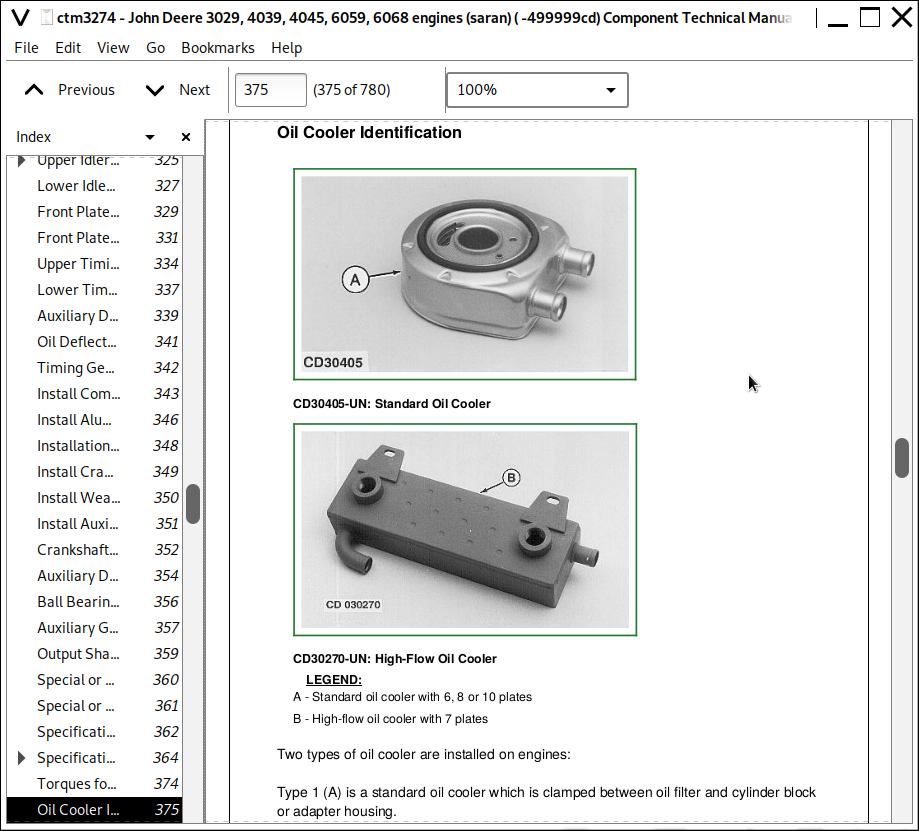
Oil Cooler Identification
Standard Oil Cooler Removal
Standard Oil Cooler Adapter Replacement
Standard Oil Cooler/Oil Filter Brackets Replacement
Replace Oil Filter Adapter On Engine With Remote Oil Filter
High-Flow Oil Cooler Removal
Oil Cooler Distributor Base Removal
Oil Cooler Distributor Base Repair
High-Flow Oil Cooler/Distributor Base Installation
Oil Pressure Regulating Valve Removal
Oil Pressure Regulating Valve Seat Replacement
Oil Pressure Regulating Valve Installation
Dipstick Guide Replacement
Oil By-Pass Valve Replacement
Oil Suction Screen Replacement (On Standard Oil Pump)
Oil Suction Screen Replacement (On High-Flow Oil Pump)
Oil Pump Identification
Standard Oil Pump Removal
Gear Axial Clearance (Standard Oil Pump)
Gear Radial Clearance (Standard Oil Pump)
Standard Oil Pump Specifications
Standard Oil Pump Installation
High-Flow Oil Pump Removal
Gear Axial Clearance (High-Flow Oil Pump)
Gear Radial Clearance (High-Flow Oil Pump)
High-Flow Oil Pump Specifications
High-Flow Oil Pump Installation
Oil Pan Installation
Group 30: Cooling System
Special or Essential Tools
Specifications
Torques for Hardware
Water Pump - Exploded View
Water Pump Identification
Water Pump Removal
Disassemble Water Pump (Standard Model)
Water Pump Bearing Shaft Installation
Water Pump Seal Installation
Water Pump Impeller Installation
Install Pulley or Hub
Install Water Pump
Water Pump With Rotating Assembly - Exploded View
Rotating Assembly Removal
Disassembling Rotating Assembly
Reassembling Rotating Assembly
Rotating Assembly Installation
Thermostat Test and Replacement
Cooling System Deaeration
Check Fan/Alternator Belt Tension
Install Fan
Install Engine Fan Pulley on 2054 and 2254 Combines (With CD6060HZ001 Engines)
Coolant Heater Operation (4 and 6 Cyl. Engines)
Replacing the Coolant Heater (4 and 6 Cyl. Engines)
Coolant Heater Operation (All Engines)
Group 35: Air Intake and Exhaust System
Specifications
Torques for Hardware
Intake Manifold Inspection
Exhaust Manifold Inspection
Turbocharger Removal
Radial Bearing End Play Check (GARRETT Turbocharger)
Check Radial Bearing Clearance (SCHWITZER Turbocharger)
Axial End Play Check
Turbocharger Repair
Turbocharger Disassembly
Turbocharger Reassembly
SCHWITZER Turbocharger Model S2A
Prelube Turbocharger
Turbocharger Installation
Turbocharger Break-In
Recommendations for Turbocharger Use
Group 40: Fuel System
Special or Essential Tools
Self-Manufactured Tool Template for Front Plate Replacement
Self-Manufactured Tool Example of Stationary Pointer for Dynamic Timing
Specifications
Specifications - Mannheim Tractors
Torques for Hardware
Rectangular Fuel Filter Element Replacement
Replace Round Fuel Filter Element
Replace Round Fuel Filter Assembly
Fuel Pump Replacement
Lucas CAV Fuel Injection Pump Removal
Repairs to Fuel Injection Pump
Lucas CAV Fuel Injection Pump Installation
Lucas CAV Fuel Injection Pump Static Timing
STANADYNE DB2 or DB4 Fuel Injection Pump Removal
Repairs to Fuel Injection Pump
Replace Throttle Lever (STANADYNE)
STANADYNE DB2 or DB4 Fuel Injection Pump Installation
STANADYNE DB2 or DB4 Fuel Injection Pump Static Timing
Engine Front Plate Replacement
STANADYNE DM4 Fuel Injection Pump Removal
Repairs to Fuel Injection Pump
STANADYNE DM4 Fuel Injection Pump Installation and Timing
Remove Fuel Supply Pump on MICO In-Line Fuel Injection Pump
Test MICO Fuel Supply Pump for Leaks
Disassemble MICO Fuel Supply Pump
Assemble MICO Fuel Supply Pump
Install Fuel Supply Pump On In-Line Fuel Injection Pump
Service Injection Pump Overflow Valve (In-Line Injection Pump)
Remove MICO In-Line Injection Pump
JDG670A Modification
Repair MICO In-Line Fuel Injection Pump
Install MICO In-Line Fuel Injection Pump
Dynamic Timing (All Pump Types)
Install Timing Sensor
Install Magnetic Probe (For Use Without Stroboscopic Lamp)
Install Stationary Pointer (For Use With Stroboscopic Lamp)
Timing Sensor and Magnetic Probe Connection
Dynamic Timing at Full Load Rated Speed Using Magnetic Probe
Dynamic Timing at No-Load
Aneroid Replacement
Aneroid Field Adjustment
Aneroid Workshop Adjustment
Fuel Injection Nozzle Removal
Clean Fuel Injection Nozzle
Fuel Injection Nozzle Test
Fuel Injection Nozzle Disassembly
Adjust Fuel Injection Nozzle
Install Fuel Injection Nozzle
Bleed the Fuel System at Fuel Filter
Bleed Fuel System (Lucas-CAV)
Bleed Fuel System (STANADYNE)
Bleed Fuel System (MICO In-Line Injection Pump)
Bleed Fuel System at Fuel Injection Nozzles
Adjust Engine Speed On Distributor Injection Pump
Adjust Engine Speed on MICO In-Line Injection Pump
Group 205: Engine System - Operation
Engine-Sectional View
General Information
Lubrication System
Cooling System (4-Cylinder Engine)
How the 37 kW Auxiliary Drive Works
Group 210: Engine System - Diagnosis and Tests
Special or Essential Tools
Specifications
Engine Break-In Instructions
Engine Break-In Oil
Diagnosing Engine Malfunctions
Checking Engine Compression
Checking Engine Oil Pressure
Measuring Engine Blow-By
Using STANADYNE “TIME-TRAC” as Tachometer
Inspect Thermostat and Test Opening Temperature
Group 215: Air Intake System - Operation and Tests
Special or Essential Tools
Specifications
Turbocharger Operation
Turbocharger Boost Pressure Check
Diagnosing Turbocharger Malfunctions
Air-to-Air Aftercooler Operation
Group 220: Fuel System - Operation and Tests
Fuel Filter Operation
Specifications
Fuel System Operation - Distributor Injection Pump
Fuel Transfer Pump Operation (Distributor Injection Pump)
Lucas CAV Fuel Injection Pump - Sectional View
Lucas CAV Fuel Injection Pump - Operation
Test Shut-Off Solenoid on Lucas-CAV Injection Pump
STANADYNE Fuel Injection Pump (Type DM4) - Sectional View
STANADYNE Fuel Injection Pump (DM4) - Operation
STANADYNE Fuel Injection Pump (Type DB2/DB4) - Sectional View
STANADYNE Fuel Injection Pump (DB2/DB4) - Operation
Specifications (In-Line Pump)
Fuel System Operation - In-Line Injection Pump (6 Cyl. Shown)
Fuel System Operation-In-Line Injection Pump
Fuel Transfer Pump Operation (In-Line Injection Pump)
Diagnose Fuel Supply Pump Malfunctions-In-Line Injection Pump
In-Line Fuel Injection Pump Operation
Governor Operation (In-Line Pump)
Diagnose In-Line Fuel Injection Pump Malfunctions
Fuel Injection Nozzles - General Information
Diagnosing Fuel System Malfunctions
Testing Fuel Injection Nozzles On a Running Engine
Timing of Fuel Injection Pumps On Diesel Engines Using Stroboscopic Lamp
John Deere 3029, 4039, 4045, 6059, 6068 Engines Component Technical Manual (CTM3274)
![]()