
John Deere 9660 STS and 9760 STS Combines Operator's Manual - OMH230231
Catalog:
Price: US$ 39.00
John Deere 9660 STS and 9760 STS Combines Operator's Manual - OMH230231
omh230231 - 9660 STS and 9760 STS Combines Operator's Manual.pdf
Complete operator's manual for John Deere 9660 STS and 9760 STS Combines, with all the information to maintain & operate.
PRODUCT DETAILS:
Total Pages: 1,463 pages
File Format: PDF (Internal Links, Bookmarked, Table of Contents, Searchable, Printable, high quality)
Language: English
omh230231 - 9660 STS and 9760 STS Combines
Table of Contents
Foreword
Section 05: Safety Features
Combine Safety Features
Section 10: Safety
Recognize Safety Information
Understand Signal Words
Follow Safety Instructions
Driving the Combine
Keep Riders and Children Off Machine
Ballasting for Safe Ground Contact
Avoid Electrical Power Lines
Park the Combine Safely
Operate the Engine Outdoors
Handle Fuel Safely—Avoid Fires
Prepare for Emergencies
Handle Starting Fluid Safely
Wear Protective Clothing
Stay Clear of Header
Keep Hands Away From Knives
Use Safety Lights and Devices
Use Seat Belts
Transport Combine With Header Safely
Prevent Machine Runaway or Unexpected Movements
Practice Safe Maintenance
Prevent Machine Damage When Welding
Remove Paint Before Welding or Heating
Avoid Heating Near Pressurized Fluid Lines
Avoid Contact With Moving Parts
Cleaning Grain Tank and Removal of Blockages Safely
Replace Safety Signs
Avoid High-Pressure Fluids
Do Not Open High-Pressure Fuel System
Service Accumulator Systems Safely
Protect Against High Pressure Spray
Dispose of Waste Properly
Service Cooling System Safely
Remove Accumulated Crop Debris
Support Machine Properly
Service Drive Belts Safely
Section 15: Safety Sign Location
Cab View Decals
Front View Decals
Feeder House/Cab Ladder Decals
Left-Hand View Decals
Left-Hand Rear View Decals
Rear View Decals
Engine View Decals
Right-Hand Rear View Decals
Right-Hand View Decals
Top View Decals
Section 20: Controls and Instruments
General View of Controls and Instruments
Section 25: Overhead Control Panel
Overhead Control Panel
Overhead Warning Display Panel
Unloading Auger On Indicator
Low Fuel Indicator
Park Brake On Indicator
Main Gear Case Filter Restriction Indicator
Main Gear Case Temperature Indicator
High Hydraulic Oil Temperature Indicator
Abnormal Voltage Indicator
Engine Air Filter Restriction Indicator
Grain Tank Full Indicator
Abnormal Hydrostatic Charge Pressure Indicator
Main Gear Case Low Pressure Indicator
High Engine Coolant Temperature Indicator
Low Engine Oil Pressure Indicator
Slow Feed Accelerator Operation Indicator
Slow Chopper Speed Indicator (Optional)
Slow Discharge Beater Speed Indicator
Slow Auger Conveyor Speed Indicator
Clean Grain Elevator Speed Slow Indicator
Tailings Elevator Speed Slow Indicator
Threshing Slow Speed Indicator
Engine Speed Slow Indicator
CLIMATRAK Automatic Temperature Control
Mirror Control Switch (Optional)
Mirror Heater Switch (Optional)
Windshield Wiper and Windshield Washer (Optional)
Deere-Delco Radios (Optional)
Deere-Delco AM/FM Stereo Radio with Weatherband
Weatherband
Programming Radio for Local Area Frequency
Theft Deterrent Feature
Activating THEFTLOCK
Disabling THEFTLOCK
Unlocking a Locked Receiver
Deere-Delco AM/FM Radio with Weatherband and CD Player
Operating Tips About Your Audio System
Antenna
Communications/CB Radio Mounting
Section 30: COMMANDTOUCH Armrest Console
COMMANDTOUCH Console Switch and Knob Colors
COMMANDTOUCH Console Controls
Header Engage Switch and Feeder House Reverser Switch (Yellow)
Shifting Feeder House
Separator Engage Switch (Yellow)
Active Header Control (AHC) Active Header Control is a trademark of Deere & Company Dial (Black)
Reel DIAL-A-SPEED DIAL-A-SPEED is a trademark of Deere & Company Dial (Black)
Reel Manual Speed Switch (Black)
Road Transport Disconnect Switch (Black)
Draper Belt Speed Switch (Black) (Optional)
Concave Clearance Switch (Black)
Threshing Speed Switch (Black)
Cleaning Fan Switch (Black)
Power Folding Auger Switch (Black) (Optional)
Chaffer Adjust Switch (Black) (Optional)
Sieve Adjust Switch (Black) (Optional)
Spreader Speed Switch (Black)
Engine Speed Switches (Orange)
Header Response Control Dials (Black)
HYDRAFLEX HYDRAFLEX is a trademark of Deere & Company Control Switch (Black)
Four Wheel Drive (Orange) (Optional)
Multifunction Control Handle (Orange)
Multifunction Handle
Quick Stop Switch (Yellow)
Unloading Auger Swing Switch (Black)
Unloading Auger Drive Switch (Yellow)
Header Lift Switch (Black)
CONTOUR MASTER Manual Tilt Switch (Black)
Reel Lift/Reel Fore and Aft Switch (Black)
Header Activation Buttons (Black)
Section 35: COMMANDTOUCH Cab Cornerpost
COMMANDTOUCH Cab Cornerpost
Active Header Control Display
Header Height Resume
Header Height Sensing
Header Height Sensing—HYDRAFLEX HYDRAFLEX is a trademark of Deere & Company Platforms
Reel DIAL-A-SPEED System
CONTOUR MASTER System (Optional)
Active Header Float (Optional) — Rigid Platforms
Reel Position Resume/Deck Plate Position Resume
Description of Automatic Header Height Control System
VISIONTRAK Display
VISIONTRAK Display Control Button
VISIONTRAK Monitor Diagnostic Buttons
VISIONTRAK Tailings Sensor Display
VISIONTRAK Tailings Sensor Display Operational Check
VISIONTRAK Performance Monitor
VISIONTRAK Performance Monitor (General Information)
VISIONTRAK—Preliminary Adjustments on Combine
VISIONTRAK—How the Monitor Works
VISIONTRAK Performance Monitor—Operating
VISIONTRAK Operational Checks
Deck Plate Position — In Cab Adjustment (Optional on 90 Series Corn Heads)
Triple Display Tachometer
Fuel Gauge
Engine Coolant Temperature Gauge
Digital Display Lines
Diagnostic Icon
Section 40: Calibration Procedures
When to Calibrate
Concave Sensor Zero Calibration
Header Calibration
CONTOUR MASTER Angle Sensor Calibration
Active Header Float Calibration
Deck Plate Sensor Zero Calibration
Chaffer Calibration (Optional)—Field Operation
Chaffer Calibration (Optional)—Component Replacement
Sieve Calibration (Optional)—Field Operation
Sieve Calibration (Optional)—Component Replacement
Calibration Service Codes
Section 45: Operator's Station
Windshield Washer Reservoir—Filling (Attachment)
Armrest Storage Box
Manual Storage
Emergency Exit
COMFORT COMMAND COMFORT COMMAND is a trademark of Deere & Company Operator's Seat
Seat Suspension and Forward and Rearward Adjustment
Adjusting Left-Hand Armrest and Seat Back
Right-Hand Armrest and Control Console—Adjusting
Field Office Seat (Optional)
Seat Belts
Auxiliary Power Outlet Strip and SERVICE ADVISOR SERVICE ADVISOR is a trademark of Deere & Company Diagnostic Connector
GREENSTAR GREENSTAR is a trademark of Deere & Company HARVEST MONITOR HARVEST MONITOR is a trademark of Deere & Company and HARVEST DOC HARVEST DOC is a trademark of Deere & Company System (Attachment)
Cab Ladder
Cab Ladder Positions
Cab Landing Safety Chains
Fire Extinguisher
Fire Extinguisher Locations
Washing Cab Windows, Servicing Head Lights and Wiper
Right-Hand Side Cab Access
Grain Tank Window/Rear Cab Window Cleaning
Horn
Steering Column
Steering Wheel Height Adjusting
Steering Column Tilt Adjusting
Gear Shift Lever
Manual Parking Brake
Brake Pedals
Tool Box
Section 50: CLIMATRAK Air Conditioning/Heating System
Observe Air Conditioning Precautions
CLIMATRAK Air Conditioning System (General Information)
CLIMATRAK Inlet Panel—Cleaning
CLIMATRAK Precleaner—Cleaning
CLIMATRAK Fresh Air Filter—Removing
Recirculating Filter—Removing
CLIMATRAK Fresh Air Filter and Recirculating Filter—Cleaning
CLIMATRAK Evaporator Filter—Removing
CLIMATRAK High Pressure Switch
CLIMATRAK Low Pressure Switch
Section 55: Lights and Signals
Light Switches
Dimmer Switch
Cab Interior Lights
Warning Lights
Road Lights
Field Lights
Work Lights
Side Finder and Grain Tank Lights
Cleaning Shoe Lights
Work Lights (Optional)
Engine Compartment Work Lights
Rear Residue Discharge Lights
Turn Signals
Exit Lighting
Unloading Auger Light
Section 60: Feeder House
Hydraulic Cylinder Safety Stop
Feeder House Side Shields
Feeder House Doors
Feed Accelerator Top Access Door
Feeder House Bottom Door and Feedplate Seal Support
Reinforced Feedplate Support (Field Installed Attachment)
Stone Trap
Expanded Stone Trap Door (Field Installed Attachment)
Fore/Aft Tilt Frame—Adjusting
Feeder House Conveyor Chain Links—Removing
Feeder House Conveyor Chain—Adjusting
Feeder House Drum—Height Adjustment
Feeder House Conveyor Speed—Changing
Feeder House Conveyor Speed (Optional High Speed Feeder House Sprocket)—Changing
Feeder House Conveyor Drive Chain—Adjusting
Feeder House Slip Clutch
Feeder House Top Shaft Stripper—Adjustment
Feeder House Top Shaft Sprockets
Feeder House Variable Speed—Belt Replacement
Feeder House Variable Speed Belt—Adjustment
Feeder House Fixed Speed Belt—Replace and Adjust Belt
Manual Tilt Indicator (CONTOUR MASTER)
Attach Multi-Coupler and Single Point Latching
Attaching and Detaching Header from Feeder House
Single Point Latching—Adjusting
Level Land Feeder House Lower End Cable—Adjusting
Level Land Feeder House—Shim Adjusting
Feeder House Latching Pins (Cleanout)
Feeder House Manual Unlatching
Shear Screw Location
Section 65: Shields
Gull Wing Doors
Left-Hand Side Shields
Left-Hand Side Front Shield
Right-Hand Side Shields
Right-Hand Side Front Shield
Single Tine Separator Covers
Composite Panels—Cleaning
Section 70: Separator
Feed Accelerator—Wing Replacement
Standard Speed High Capacity Feed Accelerator Belt—Replacing
Optional High Speed High Capacity Feed Accelerator Belt—Replacing
Feed Accelerator Belt Idler—Adjusting
Feed Accelerator Slow Speed Drive (Attachment)
Feed Accelerator Speed
Standard Speed High Capacity Feed Accelerator—Changing
Optional High Speed High Capacity Feed Accelerator—Changing To Slow Speed
Feed Accelerator Smooth Wear Strips (Attachment)
Concave Round Bar Inserts (Attachment)
Concave Cover Plates (Attachment)
Separator Grate Spacers
Concave Sections—Remove and Install
Concave Leveling
POSI-TORQ POSI-TORQ is a trademark of Deere & Company Single Tine Separator—Dual-Range ™
Single Tine Separator Drive Sheave Gap—Adjusting
Single Tine Separator Variable Drive Belt—Replacing
Separator Grate Covers (Attachment)
Auger Bed Divider
Discharge Beater Belt—Adjusting
Discharge Beater Belt—Replacing
Discharge Beater—Wing Replacement
Header Reel/Belt Pickup Pump Belt—Adjusting
Header Reel/Belt Pickup Pump Belt—Replacing
Countershaft Right-Hand Front Belt—Adjusting
CounterShaft Right-Hand Front Belt—Replacing
Countershaft Right-Hand Rear Belt—Adjusting
CounterShaft Right-Hand Rear Belt—Replacing
Cleaning Shoe Inspection Door
Cleaning Shoe Auger Gears—Adjusting
Shoe, Fan and Conveyor Auger Belt—Adjusting
Shoe, Fan and Conveyor Auger Belt—Replacing
Cleaning Fan Belt—Replacing
Cleaning Fan Speed Actuator—Adjusting
Slow Speed Cleaning Fan Drive (Attachment)
Deep-Tooth Front Chaffer
General Purpose Chaffer, 29 mm (1-1/8 in.)
Deep-Tooth Chaffer 41 mm (1-5/8 in.) (Attachment)
Front Chaffer Divider Extensions (Attachment)
Sieve
Sieve Round Fixed Hole (Optional)
Deep Tooth Sieve 29 mm (1-1/8 in.) (Attachment)
Chaffer and Sieve Adjusting Tool Storage
Chaffer or Sieve—Adjusting
Chaffer or Sieve Indicator—Calibration
Chaffer—Remove And Install
Sieve—Remove And Install
Chaffer/Sieve Adjusting Switch (Optional)
Chaffer/Sieve Elements With (Optional) TOUCHSET Automatic Combine Adjustment (ACA)—Removing
Chaffer/Sieve Motor (Optional)—Manual Adjust
Clean Grain Elevator Top Access Doors for Drives
Clean Grain Elevator Belt—Adjusting
Clean Grain Elevator Conveyor Chain—Adjusting
Clean Grain Elevator Perforated Screens (Attachment)
Tailings Elevator Paddles
Tailings Elevator Drive Belt—Adjusting
Tailings Elevator Paddle Chain—Adjusting
Upper Tailings Auger Drive Chain—Adjusting
Left-Hand Drives
Right-Hand Drives
Rotor Anti-Wrap Kit (Field Installed Attachment)
Threshing Elements And Tines—Remove And Install
Threshing Bar and Separator Tine Locations (Standard Rotor Configuration)
Threshing Element and Separator Tine Location (Rice Rotor Configuration Option)
Feed Accelerator—Unplugging
Single Tine Separator—Unplugging
Discharge Beater—Unplugging
Section 75: Chopper and Spreader
Chopper (General Information)
Chopper Tailboard—Adjusting
Chopper Vanes—Adjusting
Chopper Vanes—Factory Settings
PowerCast Tailboard (Optional)
PowerCast Tailboard—Operating
PowerCast Tailboard Blade—Replacing
PowerCast Tailboard Rear Shrouds
Chopper Door Position
Crop Diverter
Air Chutes
Chopper Stationary Knifebank—Adjusting
Chopper Stationary Knife Blades—Replacing
Chopper Blades—Replacement And Configuration
Chopper Blade—Centering
Chopper—Lowering
Chopper Drive Speeds—Changing
Chopper Drive Belt Tension—Adjusting
Chopper Belt—Replacing
Chopper to Windrow/Servicing Position
Chopper to Windrow Position (Powered Tailboard)
Spreader (General Information)
Operating the Spreader
Spreader to Windrow Position
Spreader—Lowering
Spreader Disk Assemblies
Spreader Blade—Replacing
Section 80: Grain Tank and Unloading System
Grain Tank/Engine Ladder
Grain Tank Drain Holes
Grain Tank Sample Trough
Grain Tank Full Indicator (Optional Hilly Conditions)
Grain Tank Full Indicator
Cleanout Chute (Optional)
Grain Tank Cross Auger Covers
Unloading Auger Drive Shear Bolt
Grain Tank Loading Auger Deflector
Grain Tank Loading Auger—Folding
Unloading Auger Drive Chain—Adjusting
Unloading Auger Support Stud (Standard Grain Tank)
Unloading Auger Swing Cylinder Eyebolt—Adjusting (Standard Grain Tank)
Swing Cylinder—Adjusting (High Unload Rate Grain Tank)
Cradle Support—Adjusting (High Unload Rate Grain Tank)
Power Folding Auger (Optional) Actuator Failure—Removing
Unloading Auger Drive Belt—Replacement
Section 85: Service - Electrical System
Observe Electrical Precautions
Basic Electrical Component Handling / Precautions for Vehicles Equipped with Computer Controlled Systems
Handling Batteries Safely
Batteries—Safe Installation
Battery Cables—Connecting
Batteries—Charging
Batteries—Checking Specific Gravity
Batteries—Connecting Booster
Batteries—Removing and Installing
Battery Disconnect Switch
Starter
Alternator and Voltage Regulator
Header Drive Electromagnetic Clutch
Relays
Control Relay Board Identification
Engine Compartment Relay Panel Fuse Identification
Engine Compartment Relay Panel Identification
Safety Rules When Replacing Halogen Bulbs
Replacing Bulbs
Cab Headlight Bulb—Replacement
Cab Headlight—Adjustment
Safety Rules When Replacing High Intensity Discharge (HID) Xenon Lights
Remove and Install High Intensity Discharge (Xenon) Lights (Optional)
High Intensity Discharge (Xenon) Light—Adjustment
Front Warning Light, Road Light, Field Light Bulb Replacement
Rear Discharge Light, Auxiliary Field Light, Access Door Work Light, Grain Tank and Unloading Auger Light and (Optional) Stubble Light Bulb—Replacement
Side Finder Light Bulb—Replacement
Cleaning Shoe Light Bulb—Replacement
Warning Light Bulb—Replacement
Tail Light, Warning (Flasher) Light and Side Light Bulb—Replacement
Turn Signal Indicator Light Bulb—Replacement
Cab Dome and Console Light Bulb Replacement
Overhead Warning Display Panel Light Bulb—Replacement
Section 90: Diagnostic Trouble Codes
Control Unit Addresses
Accessing Diagnostic Trouble Codes and Addresses
Diagnostic Trouble Code Priorities
Diagnostic Trouble Codes
GREENSTAR Display and Moisture Sensor Warning Codes
Section 95: Hydraulic System
Hydraulic System (General Information)
Hydraulic System Cleanliness
Accumulator, Pressure-Limiting Valve and Pressure Sensor for Float Control
Valve for Raising/Lowering Header (Proportional Valve)
Hydraulic Pressure Diagnostic Ports and Control Scheme
Feeder House Reverser Valve and Reverser Housing
Section 100: Ground Drive and Rear Axle
Service Tires Safely
Care and Service of Tires
Tire Selection Guide
Front Tire Selection, Header Compatibility, Final Drive Selection, Row Spacing Chart
Rear Tire Selection, Tire Spacing, and Front to Rear Tire Compatibility Charts
Ballast Requirements (9660 STS)
Ballast Requirements (9760 STS)
Using Liquid Weight
Tire Loading Decal
Drive Wheel Starter Stud
Rear Wheel Bolt Torque
Drive Wheel Bolt Torque
Dual Wheels Bolt Torque
Front Drive Wheel Offset
Preparing Dual Wheel Combine for Transport or Service
Reduce Machine Weight
Remove Front Wheels—Dual Wheel Combine
Install Front Wheels—Dual Wheel Combine
Single Attach Wide Spaced Dual Wheels (Optional)
Multifunction Control Handle Linkage Adjustment
Gearshift Linkage—Adjusting
Brake System
Brake Fluid Reservoir
Jacking Locations
Combine Jack Pocket Location Decal
Section 105: Break-In Service
Breaking-In Engine
Belt Drives Adjustment - First 50 Hours
Break-In Check First 100 Hours
Break-In Check After 100 Hours
Section 110: Prestarting Checks
Engine Oil Level
Hydrostatic/Hydraulic Oil Level
Coolant Level
Fuel System (8.1 L Engine)
Fuel System (9.0 L Engine)
Fuel Tank Breather
Engine Air Scoop
Cleaning Engine Compartment
After Long Storage Period
Tires
Section 115: Operating the Engine
Starting the Engine
Warming up Engine
Stopping the Engine
Cold Weather Operation
Hot Weather Operation
Handle Starting Fluid Safely
Cold Weather Starting With Ether Starting Aid
Coolant Heater
Section 120: Service - Engine
Rear Ladder and Landing
Engine Access Covers
Cleaning Engine Compartment
Changing Starting Fluid Cans
Belt Shield
Do Not Modify Fuel System
Fuel System
Check Engine Oil
Fuel Tank—Filling
Fuel Tank—Draining
Water Separator Primary Fuel Filter (8.1 L Engine)—Draining
Water Separator Primary Fuel Filter (9.0 L Engine)—Draining
Fuel Precleaner Filter—Cleaning
Primary And Secondary Fuel Filter Element (8.1 L Engine)—Replacement
Primary And Secondary Fuel Filter Element (9.0 L Engine)—Replacement
Fuel System (8.1 L Engine)—Bleeding
Fuel System (9.0 L Engine)—Bleeding
Cooling System—Draining
Cooling System—Filling
Cooling System—Winterize
Engine Belt—Routing
Engine Accessory/Fan Drive Belt—Replacing
Rotary Screen Belt—Routing
Rotary Screen Drive Belt—Replacing
Rotary Screen, Oil Cooler, Condenser, Radiator and Charge Air Cooler—Cleaning
Rotary Screen Brush—Adjustment
Air Cleaner Filters—Removing
Inspecting Element
Section 125: Transporting
Driving the Combine on Roads
Back-Up Alarm
Transporting Combine on a Trailer
Combine Tie Down Location Decal
Towing
Pulling Combine Out of the Mud
Section 130: Harvesting Hints
Choice of Harvesting Time
Harvesting Tips
Section 135: Crop Settings and Seed Loss Chart
Crop Settings and Configuration Recommendations
Seed Loss Chart (Platforms)
Seed Loss Chart (Corn Heads)
Combine Performance Check
Power Shutdown Procedure
Section 140: TOUCHSET ACA System (Optional)
TOUCHSET Automatic Combine Adjustment (ACA) System
Customize Visible Crop Settings
Crops
TOUCHSET Automatic Combine Adjust Buttons
TOUCHSET Automatic Combine Adjust (ACA) Display Settings
Adjusting Predefined Settings
Factory Crop 2 (WHEAT 2) and Personal CROP1 — CROP5 Setting Changes (Automatic Calibration)
Setting Personal CROP1 — CROP5 and Factory CROP2 (WHEAT 2) Settings (Manual Calibration)
Section 145: GREENSTARGREENSTAR is a trademark of Deere & Company Component Location
GREENSTAR Display
Mass Flow Sensor
Moisture Sensor
DataStore
Section 150: GREENSTAR Display and Keypad
General Information
Contrast Button
Before You Start
Section 155: GREENSTAR Display Setup
GREENSTAR Display
Changing Tire Radius
System Settings
Country Code
Language
RUN Page Layout
INFO - GREENSTAR Display
Section 160: HARVEST MONITOR SETUP Functions
Harvest Monitor SETUP Chart
SETUP - Harv Mon - PAGE 1
Setup Farm
SETUP Field
Setup Custom Name
Setup Custom Name Standard/Extended Character Set
Setup Crop
Setup Header
Calibration
Standard Calibration Procedure
Optional Low Flow Compensation Procedure
Manual Adjustment of Calibration Factor
SETUP - Moisture Correction
Moisture Correction
Moisture Alarm
Moisture Curve
Moisture Curve Calibration Codes
Moisture Calibration
Record Stop Height
SETUP - Harv Mon - PAGE 2
Setup RUN Pages
Section 165: HARVEST MONITOR Run Functions
Harvest Monitor RUN Chart (Default)
RUN - PAGE 1
Run - PAGE 2
Section 170: HARVEST MONITOR Information Functions
Harvest Monitor Info Functions Chart
INFO - Harvest Monitor
INFO - View Menu - Field Totals
INFO - View Menu - Crop Totals
INFO - Menu - View Custom Names
INFO - Clear
INFO - Clear - Field Totals
INFO - Clear - Crop Totals
INFO - Clear - Custom Farm Names
INFO - Clear - Custom Field Names
INFO - Diagnostics
INFO - Diag MS - PAGE 1Moisture Sensor
INFO - Diag MS - PAGE 2 Moisture Sensor
INFO - Diag MS PAGE 3
INFO - Diag Mass Flow Sensor
INFO - Combine Network
INFO - Recent Problems
Section 175: HARVEST MONITOR Specifications
Standard Payable Moisture and Density Chart
Standard Weights
Section 180: HARVEST MONITOR Troubleshooting
Moisture Sensor
Mass Flow Sensor
GREENSTAR Display
Section 185: Combine Cleanout
Cleaning Out the Combine
Section 190: Fuels and Lubricants
Handle Fuel Safely—Avoid Fires
Handling and Storing Diesel Fuel
Diesel Fuel
Biodiesel Fuel
Lubricity of Diesel Fuel
Testing Diesel Fuel
Heavy Duty Diesel Engine Coolant
Operating in Warm Temperature Climates
Supplemental Coolant Additives
Additional Information About Diesel Engine Coolants and John Deere LIQUID COOLANT CONDITIONER
Testing Diesel Engine Coolant
Diesel Engine Break-In Oil
Diesel Engine Oil
Extended Diesel Engine Oil Service Intervals
OILSCAN OILSCAN is a trademark of Deere & Company. and COOLSCAN COOLSCAN is a trademark of Deere & Company.
Hydrostatic Drive System, Main Hydraulic System and Main Engine Gear Case Oils
Transmission, Final Drives, Feeder House Reverser, Loading Auger, Primary Countershaft and Two-Speed Separator Drive Gear Cases
Grease
Brake Fluid
Lubricant Storage
Alternative and Synthetic Lubricants
Mixing of Lubricants
Section 195: Lubrication and Maintenance
Service Intervals
Lubrication Decal Locations
Lubrication Symbols
Every 10 Hours
Every 10 Hours
Every 50 Hours
Every 50 Hours
First 100 Hours
Every 200 Hours
Every 200 Hours
Every 250 Hours
Every 400 Hours
Every 400 Hours
Every 400 Hours
Every 400 Hours
Every 400 Hours
Every 500 Hours
Every 1500 Hours or Two Years
Every 2000 Hours
Service As Required
Replace Front Engine Crankshaft Damper—4500 Hours or Five Years
Care and Maintenance of Belts
Cleaning Combine
Section 200: Troubleshooting
Feeder House
Separator
Hydrostatic Ground Drive
Four Wheel Drive (Optional)
Steering
Brakes
Engine
Heater
Air Conditioning
Section 205: Storage
Preparing Combine for Storage
Removing Combine From Storage
Section 210: Specifications
Operating Speeds
Specifications - 9660 STS Combine
Specifications - 9760 STS Combine
Dimensions (Non-Powered and Powered Unloading Auger)
Dimension Reference Points
Dimensions (Powered Folding Unloading Auger Transport Position)
Dimension Reference Points
Unified Inch Bolt and Screw Torque Values
Metric Bolt and Screw Torque Values
Section 215: Machine Identification Numbers
Identification Plates
Combine Identification Number
Engine Serial Number (8.1 L Engine)
Engine Serial Number (9.0 L Engine)
Hydrostatic Drive Unit Pump
Hydrostatic Drive Unit Motor
Two Speed Four Wheel Drive Motor
Engine Gear Case
STS Rotor Drive Gear Case
Transmission
Feeder House Reverser
Keep Proof of Ownership
Keep Machines Secure
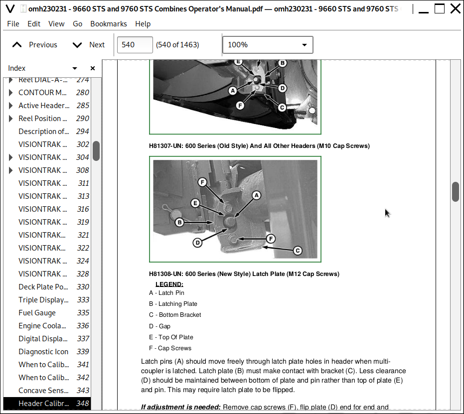
![]()