
John Deere XUV Gator Utility Vehicle 855D Repair Service Manual (tm107219)
Complete service repair manual with Electrical Wiring Diagrams for John Deere XUV Gator Utility Vehicle 855D, with all the technical information to maintain, diagnose, repair, and rebuild like professional mechanics.
John Deere XUV Gator Utility Vehicle 855D workshop service repair manual includes:
* Numbered table of contents easy to use so that you can find the information you need fast.
* Detailed sub-steps expand on repair procedure information
* Numbered instructions guide you through every repair procedure step by step.
* Troubleshooting and electrical service procedures are combined with detailed wiring diagrams for ease of use.
* Notes, cautions and warnings throughout each chapter pinpoint critical information.
* Bold figure number help you quickly match illustrations with instructions.
* Detailed illustrations, drawings and photos guide you through every procedure.
* Enlarged inset helps you identify and examine parts in detail.
tm107219 - John Deere XUV Gator Utility Vehicle 855D Technical Manual.pdf
tm107219 - John Deere XUV Gator Utility Vehicle 855D Technical Manual.epub
PRODUCT DETAILS:
Total Pages: 1,408 pages
File Format: PDF/EPUB/MOBI/AZW (PC/Mac/Android/Kindle/iPhone/iPad; bookmarked, ToC, Searchable, Printable)
Language: English
tm107219 - XUV Gator Utility Vehicle 855D
Table of Contents
Foreword
Section 10: General Information
Group 05: Safety
Recognize Safety Information
Understand Signal Words
Practice Safe Maintenance
Use Proper Tools
Handle Fluids Safely—Avoid Fires
Prevent Acid Burns
Prevent Battery Explosions
Handling Batteries Safely
Prepare for Emergencies
Park Machine Safely
Support Machine Properly
Wear Protective Clothing
Work in Clean Area
Service Machines Safely
Work In Ventilated Area
Illuminate Work Area Safely
Replace Safety Signs
Use Proper Lifting Equipment
Follow Tire Recommendations
Protect Against High Pressure Spray
Decommissioning — Proper Recycling and Disposal of Fluids and Components
Live With Safety
Group 10: General Specifications
Service Recommendations for O-Ring Boss Fittings
Service Recommendations For Flat Face O-Ring Seal Fittings
Metric Cap Screw Torque Values—Grade 7
Metric Bolt and Screw Torque Values
Unified Inch Bolt and Screw Torque Values
Group 15: Fuel, Lubricants, and Coolant
Transmission and Hydraulic Oil
Diesel Fuel—North America
Diesel Fuel—Europe
Diesel Fuel Storage
4-Cycle Diesel Engine Oil—North America
Diesel Engine Oil—Europe
Grease - North America
Grease - Europe
Mixing of Lubricants
Alternative Lubricants
Synthetic Lubricants
Lubricant Storage
Operating in Warm Temperature Climates
Diesel Engine Coolant (engine without wet sleeve cylinder liners)
John Deere COOL-GARD™ II Coolant Extender
Testing Diesel Engine Coolant
Group 20: Machine Specifications
Product Serial Number
Section 20: Engine Repair
Group 10: Engine
Summary of References
Essential or Recommended Tools
Other Material
Specifications
Remove and Install Engine
Remove and Install Muffler
Remove and Install Exhaust Manifold
Remove and Install Rocker Arm Cover
Remove and Install Rocker Arm and Push Rods
Remove and Install Cylinder Head
Recondition Cylinder Head
Remove and Install Rear Crankshaft Oil Seal
Remove and Install Front Crankshaft Oil Seal
Remove and Install Timing Gear Cover
Check Camshaft End Play
Check Timing Gear Backlash
Remove and Install Idler Gear
Remove and Install Cam Followers
Remove and Install Camshaft
Remove and Install Oil Pan and Strainer
Check Connecting Rod Side Play
Check Crankshaft End Play
Check Connecting Rod Bearing Clearance
Check Crankshaft Main Bearing Clearance
Remove, Inspect, and Install Connecting Rod
Disassemble and Assemble Pistons
Cylinder Bore
Remove and Install Crankshaft and Main Bearings
Remove and Install Flywheel
Remove and Install Flywheel Plate
Remove and Install Timing Gear Housing
Remove and Install Oil Pump
Remove and Install Coolant Temperature Switch
Remove and Install Thermostat
Remove and Install Water Pump
Remove and Install Fuel Filter
Remove and Install Fuel Filter Assembly
Remove and Install Fuel Transfer Pump
Remove and Install Fuel Injection Nozzle
Remove and Install Fuel Injection Pump
Remove and Install Fuel Control and Governor Linkage
Remove and Install Fuel Shutoff Solenoid
Repair Starting Motor
Repair Alternator
Section 30: Electrical Repair
Group 10: Wiring Harnesses (SN -060000)
Summary of References
Electrical Wiring Harness Legend (SN -060000)
Main Wiring Harness (SN -060000)
Main Harness Wire Color Codes (SN -060000)
W2 Battery Wiring Harness (SN -060000)
Battery Harness Wire Color Codes (SN -060000)
Group 15: Wiring Harnesses (SN 060001-100000)
Summary of References
Electrical Wiring Harness Legend (SN 060001-)
Main Wiring Harness (SN 060001-080000)
Main Harness Wire Color Codes (SN 060001-080000)
Main Wiring Harness (SN 080001-100000)
Main Harness Wire Color Codes (SN 080001-100000)
W2 Battery Wiring Harness (SN 060001-)
Battery Harness Wire Color Codes (SN 060001-)
Load Center (SN 060001-)
Group 20: Wiring Harnesses (SN 100001-)
Summary of References
Main Wiring Harness (SN 100001-)
Main Wiring Harness Color Codes (SN 100001-)
Main Wiring Harness Splice Table (SN 100001-)
Main Wiring Harness Terminal Table (SN 100001-)
Load Center (SN 100001-)
Group 25: Wiring Harnesses, Kits
Summary of References
Cargo Box Lift Wiring Harness
Cargo Box Lift Harness Wire Color Codes
Light and Horn Wiring Harness
Light and Horn Wire Color Codes
Lights Wiring Harness, AM140950
Lights Wiring Harness, AM137558
Headlight Jumper Wiring Harness, AM147740
Turn Signal with Flasher Harness, AM143722
Taillight Harness, AM137737
Trailer Connector Wiring Harness
Backup Alarm Wiring Harness, AM144181
Cab Power Splitter Wiring Harness, AM140972
Canopy Wiring Harness, AM143139
Roof Work Lights Wiring Harness, AM146905
Beacon Light Wiring Harness, AM140971
Horn Wiring Harness, VGA10903
Winch Main Wiring Harness, AM144137
Winch Control Wiring Harness, AM142263
Group 30: MFWD Service Kit Wiring Harnesses
Summary of References
Wiring Harness AM145249
Wiring Harness AM146628
Wiring Harness AM147221
Section 40: Power Train Repair
Group 10: Transmission
Summary of References
Service Equipment and Tools
Other Material
Specifications
Change Transmission Oil
Clean Primary Drive Clutch
Remove and Install Clutch Housing (SN -060000)
Remove and Install Clutch Housing (SN 060001-)
Remove and Install Clutch (SN -060000)
Remove and Install Clutch (SN 060001-)
Repair Drive Clutch (SN -060000)
Repair Drive Clutch (SN 060001-)
Repair Driven Clutch (SN -060000)
Repair Driven Clutch (SN 060001-)
Remove Transmission
Install Transmission
Disassemble Transaxle
Assemble Transmission
Group 15: Axles and Drive Shaft
Summary of References
Essential or Recommended Tools
Specifications
Remove and Install EMFWD Driveshaft
Replace EMFWD Driveshaft Boot
Remove and Install Rear Axle Half Shaft
Remove and Install Front Axle Half Shaft
Repair CV Joint and Boots - Front Axle Half Shafts
Repair CV Joint and Boots - Rear Axle Half Shafts
Hub Removal
Hub Installation
Group 20: Mechanical Four Wheel Drive
Summary of References
Other Material
Specifications
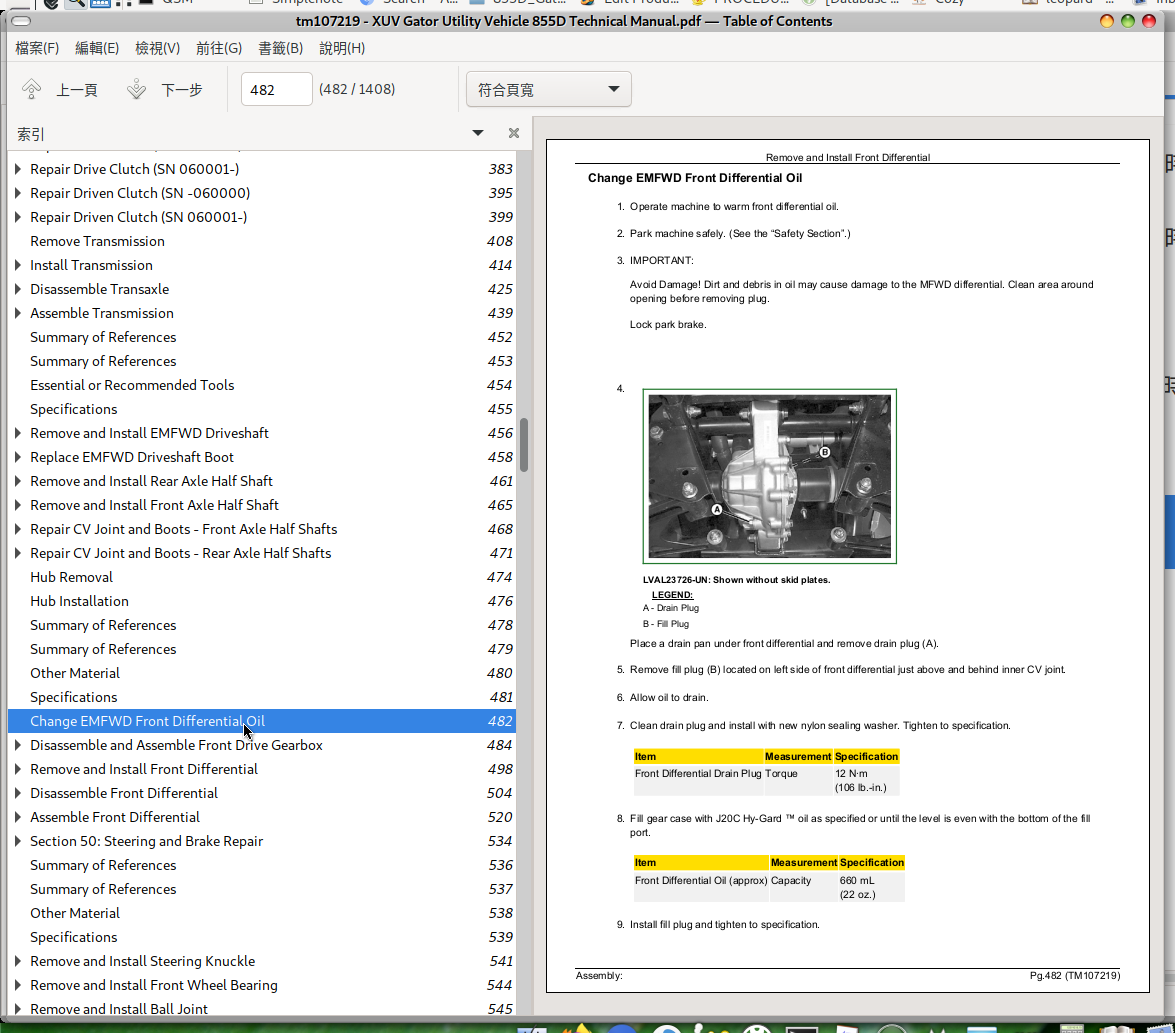
Change EMFWD Front Differential Oil
Disassemble and Assemble Front Drive Gearbox
Remove and Install Front Differential
Disassemble Front Differential
Assemble Front Differential
Section 50: Steering and Brake Repair
Group 10: Steering
Summary of References
Other Material
Specifications
Remove and Install Steering Knuckle
Remove and Install Front Wheel Bearing
Remove and Install Ball Joint
Remove and Install Steering Wheel
Remove and Install Electric Power Assisted Steering (EPAS) Module
Remove and Install Steering Shaft
Remove and Install Steering Shaft (EPAS)
Replace Steering Shaft Bearing
Remove and Install Steering Gearbox
Remove and Install Front Coilover Shock Absorber
Remove and Install Rear Coilover Shock Absorber
Remove and Install Tie Rod End
Remove and Install Front Suspension Arm
Remove and Install Rear Axle Bearing Carrier
Remove and Install Rear Suspension Arm
Remove and Install Front Suspension Arm Bushing
Remove and Install Rear Suspension Arm Bushing
Remove and Install Rear Stabilizer Bar
Group 20: Brakes
Summary of References
Service Equipment and Tools
Other Material
Specifications
Replace Brake Pad
Remove and Install Master Cylinder
Remove and Install Brake Line
Remove and Install Brake Caliper
Remove and Install Brake Rotor
Remove and Install Brake Pedal
Remove and Install Park Brake Control Cable
Remove and Install Park Brake Lever
Disassemble and Assemble Park Brake
Section 60: Miscellaneous Repair
Group 10: Wheels
Summary of References
Specifications
Remove and Install Wheels
Group 15: Hood, Cargo Box, and Bumper
Summary of References
Specifications
Remove and Install Hood Latch
Remove and Install Hood
Remove and Install Front Bumper/Skid Plate
Remove and Install Cargo Box
Remove and Install Cargo Box Side
Group 20: Miscellaneous
Summary of References
Specifications
Remove and Install Headlight
Remove and Install Front Grille
Remove and Install Front Fender
Door Removal and Installation
Door Alignment
Door Latch Adjustment
Radiator Drain and Flush Procedure
Radiator Fill and Bleed Procedure
Remove and Install Radiator
Remove and Install Cooling Fan
Remove and Install Battery
Remove and Install Fuel Tank
Section 70: Operator’s Station Repair
Group 10: Operator’s Station and Seat
Summary of References
Specifications
Remove and Install Dash Panel
Remove and Install Seat
Remove and Install Bench Seat
Remove and Install Seat Base Cover
Remove and Install Seat Adjuster
Remove and Install Under Seat Storage Box (Bench Seat)
Remove and Install Center Console
Remove and Install Transaxle Control Lever Housing
Group 20: Occupant Protective Structure (OPS)
Summary of References
Specifications
Remove and Install Occupant Protective Structure (OPS)
Section 220: Engine Operation, Tests, and Adjustments
Group 10: Component Location
Summary of References
Fuel Filter Components
Engine Fuel System
Engine Mounts
Fuel System Components
Exhaust System Components (SN -080000)
Exhaust System Components (SN 080001-)
Coolant System Components
Group 15: Theory of Operation
Summary of References
Cooling System Operation
Lubrication System Operation
Fuel System Operation
Air System Operation
Group 20: Diagnosis
Engine Troubleshooting and Diagnostics
Diagnose Engine Oil
Diagnose Excessive Fuel Consumption
Diagnose Incorrect Manifold Pressure
Diagnose Low Engine Compression
Diagnose Engine Starting Problem
Diagnose Poor Engine Operation
Diagnose Abnormal Coolant Temperature
Diagnose Coolant in Oil or Oil in Coolant
Diagnose Engine
Group 25: Tests and Adjustments
Summary of References
Essential or Recommended Tools
Other Material
Specifications
Test Air Restriction Indicator
Adjust Fast Idle Speed
Adjust Slow Idle
Adjust Throttle Cable
Adjust Valve Clearance
Check Valve Lift
Test Cylinder Compression
Adjust Water Pump/Alternator Drive Belt
Test Thermostat
Test Radiator Bubble
Test Cooling System Pressure
Test Radiator Cap Pressure
Test Engine Oil Pressure
Test Fuel Injection System
Test Fuel Injection Nozzle
Adjust Injection Pump Timing
Check Injection Pump Static Timing
Bleed Fuel System Air
Test Fuel Transfer Pump Flow
Test Fuel Transfer Pump Pressure
Section 230: Electrical Operation, Tests, and Adjustments
Group 05: General Information
Operation and Diagnostics
Diagnostic Information
Wire Color Abbreviation Chart
Reading Electrical Schematics
Common Circuit Tests
Conductors for 12 Volt Circuits
Group 10: Component Location
Summary of References
Fuse Block and VCU Fuses (SN -060000)
Load Center Components (SN 060001-)
Group 15: Theory of Operation (SN -060000)
Summary of References
Power Circuit Operation (SN -060000)
Charging Circuit Operation (SN -060000)
Cranking Circuit Operation (SN -060000)
Seat Belt Circuit Operation (SN -060000)
Glow Plug Circuit Operation (SN -060000)
Fuel Shutoff Circuit Operation (SN -060000)
Engine Oil Pressure Light and Hour Meter Circuit Operation (SN -060000)
Park Brake Circuit Operation (SN -060000)
4WD Circuit Operation (SN -060000)
Engine Cooling Circuit Operation (SN -060000)
Headlight Circuit Operation (SN -060000)
Accessory Power Port Circuit Operation (SN -060000)
Cargo Box Lift Circuit Operation (SN -060000)
Group 20: Theory of Operation (SN 060001-)
Summary of References
Power Circuit Operation (SN 060001-080000)
Power Circuit Operation (SN 080001-100000)
Power Circuit Operation (SN 100001-)
Charging and Tachometer Circuit Operation (SN 060001-)
Seat Belt Circuit Operation (SN 060001-)
Park Brake Light and Warning Buzzer Circuit Operation (SN 060001-)
Cranking, Glow Plug, Fuel Gauge Circuit Operation (SN 060001-080000)
Cranking, Glow Plug, Fuel Gauge Circuit Operation (SN 080001-)
4WD and Speedometer Circuit Operation (SN 060001-100000)
4WD and Speedometer Circuit Operation (SN 100001-)
Engine Cooling Circuit Operation (SN 060001-)
Light Circuit Operation (SN 060001-080000)
Light Circuit Operation (SN 080001-)
Electric Power Assist Steering (EPAS) Operation (SN 060001-)
Group 25: Diagnosis (SN -060000)
Power Circuit Diagnosis (SN -060000)
Charging Circuit Diagnosis (SN -060000)
Cranking Circuit Diagnosis (SN -060000)
Seat Belt Circuit Diagnosis (SN -060000)
Glow Plug Circuit Diagnosis (SN -060000)
Fuel Shutoff Circuit Diagnosis (SN -060000)
Engine Oil Pressure Light Diagnosis (SN -060000)
Hour Meter Circuit Diagnosis (SN -060000)
Park Brake Circuit Diagnosis (SN -060000)
4WD Circuit Diagnosis (SN -060000)
Cooling Circuit Diagnosis (SN -060000)
Headlight Circuit Diagnosis (SN -060000)
Cargo Box Lift Circuit Diagnosis (SN -060000)
Group 30: Diagnosis (SN 060001-)
Power Circuit Diagnosis (SN 060001-)
Charging Circuit Diagnosis (SN 060001-)
Seat Belt Circuit Diagnosis (SN 060001-)
Park Brake Light and Warning Buzzer Circuit Diagnosis (SN 060001-)
Cranking Circuit Diagnosis (SN 060001-)
4WD Drive Circuit Diagnosis (EMFWD) (SN 060001-)
Cooling Circuit Electrical Diagnosis (SN 060001-)
Light Circuit Diagnosis (SN 060001-)
Cargo Box Lift Circuit Diagnosis (SN 060001-)
Group 32: Operation and Diagnostics - Electronic Controllers (SN 060001-)
Summary of References
On Board Diagnostics - VCU (SN 060001-)
Vehicle Control Unit (VCU) Operation (SN 060001-)
Display Panel Operation (SN 060001-)
Display Panel Replacement Programming (SN 060001-100000)
Display Panel Replacement Programming (SN 100001-)
Display Panel Tire Size Programming (SN 060001-)
Overtemp Input (SN 060001-)
Oil Pressure Input (SN 060001-)
Coolant Temperature Gauge (SN 060001-)
Fuel Level (SN 060001-)
Tachometer (SN 060001-)
Speedometer (SN 060001-)
EPAM Test (SN 060001-)
Group 34: MFWD Service Kit Operation and Wiring Schematics
Summary of References
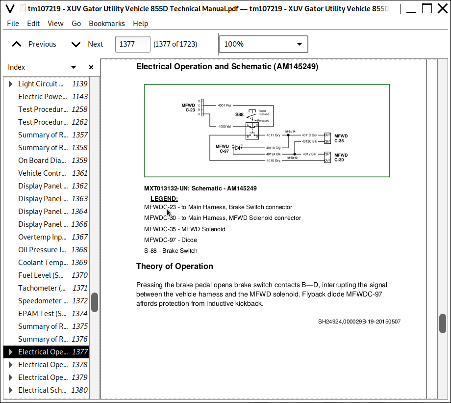
Electrical Operation and Schematic (AM145249)
Electrical Operation and Schematic (AM146628)
Electrical Operation and Schematic (AM147221)
Group 35: Wiring Schematics (SN -060000)
Electrical Schematic Legend (SN -060000)
Main Schematic (SN -060000)
Group 40: Wiring Schematics (SN 060001-100000)
Summary of References
Electrical Schematic Legend (SN 060001-080000)
Main Schematic (SN 060001-080000)
Electrical Schematic Legend (SN 080001-100000)
Main Schematic (SN 080001-100000)
Group 45: Wiring Schematics (SN 100001-)
Summary of References
Electrical Schematic Legend (SN 100001-)
Main Schematic (SN 100001-)
Group 50: Schematics, Kits and Attachments
Summary of References
Light and Horn Schematic Legend
Light and Horn Schematic
Lights Wiring Schematic, AM140950
Lights Wiring Schematic, AM137558
Turn Signal with Flasher Schematic, AM143722
Taillight Schematic, AM137737
Backup Alarm Wiring Schematic, AM144181
Canopy Wiring Schematic, AM143139
Roof Work Lights Wiring Schematic, AM146905
Beacon Light Wiring Schematic, AM140971
Horn Wiring Schematic, VGA10903
OPS Rear Lights Wiring Schematic, AM146376
Winch Schematic
Group 55: Tests and Adjustments
Summary of References
Ground Circuit Test
Battery Test
Charge Battery
Load Test Battery
Clean Battery
Regulated Voltage Output Test
Starter Solenoid Test
Starter Loaded Amperage Draw Test
Starter No-Load Amperage and RPM Test
Key Switch Test
Park Brake Switch Test
Neutral Start Switch Test
Reverse Switch Test
Headlight Switch Test (Single)
Headlight Switch Test (2 Position) (AM144577)
Light Switch Test (3 Position)
4WD Switch Test
4WD Switch Test (AM142314)
Throttle Switch Test
Brake Lights Switch Test
Raise/Lower Switch Test
Raise/Lower Switch Test (AM142315)
Relay Test
Radiator Coolant Temperature Switch Test
Engine Coolant Temperature Switch Test
Coolant Temperature Sensor Test
Engine Oil Pressure Switch Test
Glow Plug Test
Seat Belt Switch Test
Fuel Shutoff Solenoid Test
Speed Sensor Test
4WD Solenoid Test
Diode Test
Warning Alarm Test
Horn Switch Test, Push
Horn Switch Test, Toggle
Section 240: Power Train Operation, Tests, and Adjustments
Group 10: Component Location
Summary of References
Power Train Components
Front Axle Components
Rear Axle Components
MFWD Driveline Components
Front Drive Gear Box Components
EMFWD Front Differential Components
Transaxle Components
Differential Components
Transaxle Input (SN -060000)
Transaxle Input (SN 060001-)
Shift Linkage Components
Primary Clutch (SN -060000) Components
Primary Clutch (SN 060001-) Components
Secondary Clutch (SN -060000) Components
Secondary Clutch (SN 060001-) Components
Transmission Mounts Components
Group 15: Theory of Operation
Summary of References
Power Transfer Operation
Drive Clutch Operation (SN -060000)
Drive Clutch Operation (SN 060001-)
Clutch Operation (SN -060000)
Clutch Operation (SN 060001-)
EMFWD Operation
MFWD Anti-Wedging (SN -100000)
Group 20: Diagnosis
Diagnose Drive Train
Diagnose Primary Clutch
Diagnose Clutch System
Group 25: Tests and Adjustments
Summary of References
Adjust Differential Lock
Adjust Transmission Shift
Clutch Sheave Alignment (SN 060001-)
Section 250: Steering and Brake Operation, Tests, and Adjustments
Group 10: Component Location
Summary of References
Steering Components
Front Suspension Components
Rear Suspension Components
Brake System Components
Brake System Components - Front
Brake System Components - Rear
Park Brake Components
Park Brake Housing Components
Group 15: Theory of Operation
Summary of References
Steering System Operation
Brake System Operation
Group 20: Diagnosis
Diagnose Steering Pulls in One Direction
Diagnose Steering Wanders or Vibrates
Diagnose Wheel Bearing Noise
Diagnose Steering Hard in Left, Right, or Both Directions
Diagnose Steering Locks in Hard Left or Right Turn
Diagnose Steering Wheel Pulls Upwards
Diagnose Steering Wheel Spins Freely
Diagnose Noise During Turns Over Rough Terrain
Diagnose Hydraulic Brakes
Diagnose Brakes Will Not Engage or Show Poor Response
Diagnose Brake Effort Excessive
Diagnose Brakes Will Not Release
Diagnose Brakes Are Noisy or Chattering
Diagnose Excessive Brake Pad Wear
Diagnose Excessive Brake Pedal Travel
Diagnose Brakes Pull Left or Right
Diagnose Pedal Feels Hard With Little Travel
Diagnose Park Brake Will Not Engage or Hold
Diagnose Park Brake Will Not Release
Group 25: Tests and Adjustments
Summary of References
Other Material
Specifications
Center Steering Rack
Center Steering Wheel
Adjust Suspension
Adjust Toe-In
Adjust Rear Wheel Camber
Check Brake Fluid Level
Check Park Brake Lubricating Oil Level
Adjust Master Cylinder Rod
Bleed Brakes
Bleed Master Cylinder
Burnish Brakes
Section 260: Miscellaneous Operation, Tests, and Adjustments
Group 10: Component Location
Summary of References
Body Components
Seat and Seat Support Components
Bench Seat Components
Fuel System Components (SN -060000)
Fuel System Components (SN 060001-)
Section 299: Service Tools
Group 10: Service Tools and Kits
Essential or Recommended Tools
Service Kits
John Deere XUV Gator Utility Vehicle 855D Repair Service Manual (TM107219)
![]()