
John Deere Tractors 6110, 6110l, 6210, 6210l, 6310, 6310l, 6310s, 6410, 6410l, 6410s, 6510l, 6510s Diagnosis and Tests Service Technical Manual (TM4572)
Complete Diagnosis & Tests Technical Manual with electrical wiring diagrams for John Deere Tractors 6110, 6110l, 6210, 6210l, 6310, 6310l, 6310s, 6410, 6410L, 6410S, 6510L, 6510S, with workshop information to maintain, diagnose, and rebuild like professional mechanics.
tm4572 - 6110, 6110l, 6210, 6210l, 6310, 6310l, 6310s, 6410, 6410l, 6410s, 6510l, 6510s tractors Technical Manual.pdf
tm4572 - 6110, 6110l, 6210, 6210l, 6310, 6310l, 6310s, 6410, 6410l, 6410s, 6510l, 6510s tractors Technical Manual.epub
PRODUCT DETAILS:
Total Pages: 2,379 pages
File Format: PDF/EPUB/MOBI/AZW (PC/Mac/Android/Kindle/iPhone/iPad; bookmarked, ToC, Searchable, Printable)
Language: English
tm4572 - 6110, 6110l, 6210, 6210l, 6310, 6310l, 6310s, 6410, 6410l, 6410s, 6510l, 6510s tractors
Table of Contents
Foreword
Section 210: Safety
Group 05: Safety Measures
Recognize Safety Information
Prevent Machine Runaway
Handle Fluids Safely-Avoid Fires
Prevent Battery Explosions
Prepare for Emergencies
Prevent Acid Burns
Avoid High-Pressure Fluids
Service Cooling System Safely
Remove Paint Before Welding or Heating
Avoid Heating Near Pressurized Fluid Lines
Work In Ventilated Area
Wear Protective Clothing
Practice Safe Maintenance
Park Machine Safely
Use Proper Lifting Equipment
Construct Dealer-Made Tools Safely
Support Machine Properly
Work in Clean Area
Illuminate Work Area Safely
Service Machines Safely
Use Proper Tools
Service Tires Safely
Service Front-Wheel Drive Tractor Safely
Avoid Eye Contact With Radar
Keep ROPS Installed Properly
Replace Safety Signs
Dispose of Waste Properly
Live With Safety
Section 220: Engine
Group 10: Tests
Preliminary Engine Tests
Dynamometer Test
Section 230: Fuel, Air Intake and Cooling Systems
Group 10: System Diagnosis
Fuel System
Cooling System
Group 15: Tests and Adjustments
Explanation of Tests
Safety Measures
Special or Essential Tools
Specifications
Testing the Air Intake System
Testing the Low-Pressure Switch in Air Intake System
Testing Cooling System for Leaks
Checking Expansion Tank Cap
Test Thermostat Opening Temperature
Checking the Viscous Fan Drive
Checking the Fuel Transfer Pump
Testing, Calibrating and Adjusting the Engine Control Unit (ECU)
General Information on Diagnostics
Diagnostics Program
Service Code List (ECU)
Electronic Control Unit Identification Addresses
Adjust Hand Throttle Lever and Accelerator Pedal
Group 20A: Fuel System
General Information
Description
Fuel Transfer Pump - Theory of Operation
Group 20B: Air Intake System
Air Cleaner - Theory of Operation
Group 20C: Cooling System
General Information
Description of Radiator
Viscous Fan Drive - Theory of Operation
Automatic Drive Belt Tensioner - Theory of Operation
Group 20D: Cold Weather Starting Aids
General Information
Electrical Starting Aid Operation
Fuel Preheater - Theory of Operation
Coolant Preheater Operation
Transmission Oil Preheater Operation
Section 240: Electrical System
Group 05: General
Special or Essential Tools
Battery Operation
Troubleshooting on Battery
Procedure for Testing Batteries
Battery Specification
Check Battery Electrolyte Level and Terminals
Starting with a Booster Battery
Component Identification Table
How to Read a Functional Schematic
How to Read a Diagnostic Schematic
Wire Numbers and Color Codes
Symbols in Functional Schematic, Wiring and Harness Diagrams
Electrical System Visual Check
Electrical Circuit Malfunctions
Seven Step Electrical Test Procedure
Group 10: System Diagrams, ComfortGard ComfortGard is a trademark of Deere & Company. and Low-Clearance Cabs
Fuses
Functional Schematic and Wiring Harness Component Identification
Identification of Sections in Functional Schematic
Wiring Harness Identification in Wiring Diagrams
Functional Schematic - Complete Tractor
W3 - Wiring Harness- Engine (AL150218)
Wiring Harness for Electrical Starting Aid (W27; AL119472)
Front Corner Worklight Wiring Harness (W14; AL81307)
TLS Front Wheel Drive Axle Wiring Harness (W36; AL113493)
Front PTO Wiring Harness (W39; AL110126)
Cab Wiring Harness (W4; AL151379)
W53 - Wiring Harness - Turn Signal Light (AL150846)
7-Pin Socket Wiring Harness (W28; AL150291)
3-Pin Socket Wiring Harness (W30; AL114896)
Wiring Harness for Electronic Control Units (W34; AL150234)
Wiring Harness for Stepper Motor Drivers (W35; AL114802)
Turn Signal Lever Wiring Harness (W5; AL77212)
Windshield Wiper Switch Wiring Harness without Intermittent Wipe (W6; AL112539)
Windshield Wiper Switch Wiring Harness with Intermittent Wipe (W6; AL112652)
Cab Roof Wiring Harness (W11; AL 150707)
W56 - Wiring Harness - Turn Signal Light Adapter (AL119802)
Front Cab Roof Worklight Wiring Harness (W18; AL83139)
W7 Windshield Wiper Wiring Harness (AL79007)
W10 Rear Window Wiper Wiring Harness (AL116544)
Rear Window Wiper Adapter Harness (W38; AL116548)
Air Conditioning and Fan Wiring Harness (W8; AL110248)
W13 Transmission Wiring Harness (AL152964)
Transmission Wiring Harness with Electrical Reverser Control (W20; AL112509)
W40 - Wiring Harness - Back-Up Alarm (AL117624)
W41 - Wiring Harness - Back-Up Alarm -Switch for SynchroPlus Transmission (AL114955)
W42 - Wiring Harness -Switch for PowrQuad Transmission Back-Up Alarm (AL115426)
W21 - Wiring Harness - Shift Console Light- in Low-Clearance Cab (AL115043)
W22 - Wiring Harness - Dome Light- in Low-Clearance Cab (AL115041)
W24 - Wiring Harness - Windshield Wiper- in Low-Clearance Cab (AL115094)
W23 - Wiring Harness - Rear Window Wiper- in Low-Clearance Cab (AL115038)
Group 10A: System Diagrams, 2-Post ROPS
Fuses
Component Designations on Functional Schematics and Wiring Harnesses
Section Designations on Functional Schematics
Wiring Harness Identification
Functional Schematic - Complete Tractor
W3 - Wiring Harness- Engine (AL 117076)
Wiring Harness for Electrical Starting Aid (W27; AL119472)
Front Corner Worklight Wiring Harness (W14; AL81307)
Platform Wiring Harness (W4; AL117225) up to Serial Number 249394
Platform Wiring Harness (W4; AL119281) from Serial Number 249395
7-Pin Socket Wiring Harness (W28; AL150291)
3-Pin Socket Wiring Harness (W30; AL114896)
Front Part of Transmission Wiring Harness (W32; AL115344)
Rear Part of Transmission Wiring Harness (W33; AL116810)
W40 - Wiring Harness - Back-Up Alarm (AL117624)
W41 - Wiring Harness - Back-Up Alarm -Switch for SynchroPlus Transmission (AL114955)
W42 - Wiring Harness -Switch for PowrQuad Transmission Back-Up Alarm (AL115426)
Group 15: Sub-System Diagnostics, ComfortGard ComfortGard is a trademark of Deere & Company. and Low Clearance
Special or Essential Tools
SE1 Starter and Charging Circuits, Functional and Diagnostic Schematic
SE2-Basic Informator, Functional and Diagnostic Schematic
SE3-Horn, Functional and Diagnostic Schematic
SE4-Cigarette Lighter and Operator Seat, Functional and Diagnostic Schematic
SE5-Front PTO, Functional and Diagnostic Schematic
SE6-Lighting Circuits, Functional and Diagnostic Schematic
SE7-Work Lights, Functional and Diagnostic Schematic
SE8-Front Loader Plug, Functional and Diagnostic Schematic
SE9-Radio, Digital Clock, Dome and Console Lights, Functional and Diagnostic Schematic
SE10-Fan and Air Conditioner, Functional and Diagnostic Schematic
SE11-Windshield Wiper/Washer, Functional and Diagnostic Schematic
SE12-Rear Window Wiper and Washer, Functional and Diagnostic Schematic
S13-Beacon, Functional and Diagnostic Schematic
SE14-3- and 7-Pin Receptacles, Functional and Diagnostic Schematic
SE15-Electronic Hitch Control, Functional and Diagnostic Schematic (Cab)
SE16A-Basic Control Unit - Braking System, Functional and Diagnostic Schematic
SE16B-Basic Control Unit (BCU) (Hazard Flasher and Turn Signal Unit)
SE16C-Basic Control Unit - Differential Lock, Functional and Diagnostic Schematic
SE16D-Basic Control Unit - Radar, Functional and Diagnostic Schematic
SE16E-Basic Control Unit - Rear PTO without HMS, Functional and Diagnostic Schematic
SE16F-Basic Control Unit - Seat Indicator, Functional and Diagnostic Schematic
SE16G-Basic Control Unit - Front Wheel Drive without HMS, Functional and Diagnostic Schematic
SE16H-Basic Control Unit - Power Supply and Tachometer Sender, Functional and Diagnostic Schematic
SE16I-Basic Control Unit - Headland Management System, Functional and Diagnostic Schematic
SE17-Signal Socket, Functional and Diagnostic Schematic
SE18-Performance Monitor, Functional and Diagnostic Schematic
SE19-Electrical Reverser Control, Functional and Diagnostic Schematic
SE20-TLS Front Wheel Drive Axle, Functional and Diagnostic Schematic
SE21A-AutoQuad Transmission Shift, Functional and Diagnostic Schematic
SE21B-Electronic Controlled Independent Control Valves (EICV), Functional and Diagnostic Schematic
SE21C-EICV Stepper Motor Driver, Functional and Diagnostic Schematic
SE21D-Stepper Motor Driver for Autoquad Transmission, Functional and Diagnostic Schematic
SE22-Bus Terminator and Terminating Resistor, Functional and Diagnostic Schematic
SE23-Electronic Engine Control, Functional and Diagnostic Schematic
SE25-Back-Up Alarm, Functional and Diagnostic Schematic
Group 15A: Sub-System Diagnostics, 2-Post ROPS
Special or Essential Tools
SE1-Starting Motor and Charging Circuit, Functional and Diagnostic Schematic
SE2-Basic Informator, Functional and Diagnostic Schematic
SE3-Horn, Functional and Diagnostic Schematic
SE5-Rear PTO, Functional and Diagnostic Schematic
SE6-Lights, Functional and Diagnostic Schematic
SE7-Work Lights, Functional and Diagnostic Schematic
SE8-Front Loader Plug, Functional and Diagnostic Schematic
SE14-3-Pin- and 7-Pin Receptacle, Functional and Diagnostic Schematic
SE15-Electronic Hitch Control, Functional and Diagnostic Schematic (2-Post ROPS)
SE16A-Hazard Flashers and Turn Signals, Functional and Diagnostic Schematic (up to Serial No. 249394)
SE16A-Hazard Flashers and Turn Signals, Functional and Diagnostic Schematic (from Serial No. 249395)
SE16B-Front Wheel Drive, Functional and Diagnostic Schematic
SE16C-Differential Lock, Functional and Diagnostic Schematic
SE25-Back-Up Alarm, Functional and Diagnostic Schematic
Group 16A: Data-BUS-Systems –– Theory of Operation
Data BUS Systems
CCD BUS System
CAN Bus System
CCD BUS Diagnostic Schematic
CAN BUS Diagnostic Schematic
DATA BUS Systems
Group 16B: Data-BUS-Systems –– Diagnostics
Explanation of Data Bus System Tests
Safety Measures
Essential Tools
Malfunctions in the Data BUS System
CCD - Test for 2-Post ROPS tractors
CCD - Test for cab tractors without RCU and/or SFA
CCD - Test for cab tractors equipped with RCU and/or SFA
11-BIT CAN BUS Test
29-BIT CAN BUS Test
Electronic Control Units Supply Circuit 072
Group 20: Adjustments
Explanation of BCU, Basic Informator (BIF) and Performance Monitor (PRF) Testing
Safety Measures
Essential Tools
General Information on the Basic Control Unit (BCU)
BCU Addresses
Diagnostic Structure (BCU)
Service Code List (BCU)
Diagnostic Address List (BCU)
Diagnostic Addresses (BCU)
Display Address List (BCU)
Display Addresses (BCU)
Calibration (BCU)
Calibration Address List (BCU)
Calibration Addresses (BCU)
General Information Concerning the Basic Informator (BIF)
Basic Informator (BIF) Addresses
Diagnostic Structure (BIF)
Service Code List (BIF)
Diagnostic Address List (BIF)
Diagnostic Addresses (BIF)
Display Address List (BIF)
Display Addresses (BIF)
Calibration (BIF)
Calibration Address List (BIF)
Calibration Addresses (BIF)
General Information about the Performance Monitor (PRF)
Performance Monitor (PRF) Addresses
Diagnostic Structure (PRF)
Calibration (PRF)
Calibration Address List (PRF)
Calibration Addresses (PRF)
Calibrating the Ground Speed Sensor (Radar)
Setting Wheel Slip Back to Zero
Group 25: Component Testing
Special or Essential Tools
Specifications
SE1-Starting Motor and Charging Circuit
SE2-Instrument Unit and Lighting
SE3-Horn
SE4-Cigarette Lighter and Operator Seat
SE5-Front PTO
SE6-Lighting Circuits
SE7-Work Light
SE9-Radio, Dome and Shift Console Lights
SE10-Fan and Air Conditioner
SE11 and SE12-Windshield Wiper and Washer
S13-Beacon
SE15-Electronic Hitch Control (HCU)
SE16A-Basic Control Unit (BCU) (Braking System)
SE16B-Basic Control Unit (BCU) (Hazard Flasher and Turn Signal Unit)
SE16C-Basic Control Unit (BCU) (Differential Lock)
SE16E-Basic Control Unit (BCU) (Rear PTO)
SE16G-Basic Control Unit (BCU) (Front Wheel Drive)
SE16H-Basic Control Unit (BCU) (Power supply)
SE16I-Basic Control Unit (BCU) (Headland Management System)
SE19-Electrical Reverser Control
SE20-TLS Front Wheel Drive Axle
SE23-Engine Control Unit
Section 245: Electronic Control Units
Group 05: Operation and General Diagnostic Information
General Explanation of Testing Procedures for Electronic Control Units
Safety Information
Essential Tools
Diagnostics with Digital Display
Diagnosis with the performance monitor
Abbreviations Used in Display
Diagnostic Structure
Entering program mode
Calling Up and Deleting Service Codes
Electronic Control Units - Identification Addresses
Group BCU: BCU References
Supply Circuit 973 (BCU Functions)
MFWD Switch (S05) Circuit Test
MFWD Solenoid Valve (Y03) Circuit Test
Rear PTO Switch (S21) Circuit Test
Rear PTO Solenoid Valve (Y04) Circuit Test
Rear PTO Speed Sender (B06) Circuit Test
Differential Lock Switch (S22) Circuit Test
Differential Lock Solenoid Valve (Y05) Circuit Test
HMS Switch (S43) Circuit Test
Turn Signal Switch (S08) Circuit Test
Hazard Flasher Switch (S62) Circuit Test
BCU and Tractor System-Voltage-Circuit Test
Group BIF: BIF References
Engine Speed Signal Circuit Test (B01)
Air Filter Switch (B02) Circuit Test
Fuel Level Sender (B03) Circuit Test
Engine Oil Pressure Sender Circuit (B04) Test
Oil Filter Restriction Switch (B07) Circuit Test
Coolant Temperature Sender (B08) Circuit Test
Transmission Oil Pressure Switch (B31) Circuit Test
Transmission Oil Temperature Sender (B60) Circuit Test
BIF Supply Voltage and Tractor System Voltage Circuit Test
Alternator Circuit Test
Flasher Cycle Input Signal Circuit Test
Seat Switch (S40) Circuit Test (Tractors with Front PTO)
Group ECU: ECU References
Foot Throttle Potentiometer (B57) Supply Circuit Test
Foot Throttle Potentiometer (B57) Output Circuit Test
Cruise Control Potentiometer (A19) Supply Circuit Test
Cruise Control Potentiometer (A19) Output Circuit Test
Coolant Temperature Sensor (B56) Circuit Test
Engine Speed Sensor (B01) Circuit Test
Fuel Injection Pump Solenoid (Y13) Circuit Test
Starting Circuit Test
Group HCU: HCU References
HCU Beep Mode Test (HCU 02)
Quick Raise/Lower Rocker Switch (S24) Circuit Test
L.H. Draft Sensor (B20) Signal Circuit Test
R.H. Draft Sensor (B19) Signal Circuit Test
Load/Depth Control Potentiometer (B26) Signal Circuit Test
Hitch Height Control Potentiometer (B27) Signal Circuit Test
Position Sensor Potentiometer (B21) Signal Circuit Test
Raise-Limit Control Potentiometer (B27) Signal Circuit Test
Rate-of-Drop Control Potentiometer (B27) Signal Circuit Test
Remote Control Switch (S68) Circuit Test
Potentiometer (B21, B26 and B27) Supply Voltage Circuit Test
Draft Sensor (B19 and B20) Supply Voltage Circuit Test
Stepper Motor (M08) Circuit Test
HCU Power Supply Circuit Test
Group PEC: PEC References
PEC Beep Mode Test (PEC 02 and PEC 03)
Upshift Circuit (S48) Test
Downshift Circuit (S49) Test
Power/ECO Mode Switch (S85) Circuit Test
Stepper Motor Driver (SMD0) Power Supply and Identification Circuit Test
Stepper Motor (M15) and Stepper Motor Driver (SMD0) Circuit Test
E-ICV –– Multi-Function Lever (S64) Axis 1 Circuit Test (Forward and Rearward Lever Position)
E-ICV –– Multi-Function Lever (S64) Axis 2 Circuit Test (Left and Right Lever Position)
E-ICV –– Multi-Function Lever (S64) Axis 3 Circuit Test (Rocker Switch - Upper and Lower Position)
E-ICV –– Multi-Function Lever Potentiometer Supply Circuit Test
E-ICV –– Transport Lock Switch (S65) Circuit Test
E-ICV –– Interlock Switch Circuit Test
E-ICV –– Stepper Motor Driver (SMD1, 2 and 3) Power Supply and Identification Circuit Test
E-ICV No.1 –– Stepper Motor (M12) and Stepper Motor Driver (SMD1) Circuit Test
E-ICV No.2 –– Stepper Motor (M13) and Stepper Motor Driver (SMD2) Circuit Test
E-ICV No.3 –– Stepper Motor (M14) and Stepper Motor Driver (SMD3) Circuit Test
Group RCU: RCU References
Recall Codes Procedure for RCU
RCU Beep Mode Test (RCU 02)
Test Procedure for Diagnostic Address RCU 03
Test Procedure for Diagnostic Address RCU 04
Test Procedure for Diagnostic Address RCU 05
Test Procedure for Diagnostic Address RCU 06
Test Procedure for Diagnostic Address RCU 07
Check Forward Solenoid (Y08) Circuit
Check Reverse Solenoid (Y09) Circuit
Group SFA: SFA References
SFA Beep Mode Test (SFA 02)
Solenoid Valve 1 (Y10) Circuit Test
Solenoid Valve 2 (Y11) Circuit Test
Position Sensor (B53) Supply Voltage Circuit Test
Position Sensor (B53) Output Circuit Test
Magnet Sending Unit (B35) Circuit Test
Hall Sending Unit (B09) Circuit Test
Test Procedure for SFA Hydraulic System
Section 250: Transmission
Group 05: Operational Checkout
Operational tests for Perma Clutch and SyncroPlus Transmission
Group 10: Troubleshooting
Explanation of System Diagnosis
Safety Precautions
Special or Essential Tools
Specifications
Hydraulic Oil Warmup
Connecting JT07115 Hydraulic Test Kit
Connecting the Sensocontrol Testing Equipment
Layout of Test Ports and Sending Units
Preliminary Checks
Checking Gear and Range Engagement
Checking Clutch Operation
Checking the Transmission Oil Filter
System (Engagement) Pressure Test
Adjusting System (Engagement) Pressure
Check Components Dependent on System (Engagement) Pressure
Checking the Filter Relief Valve
Testing the Engagement Override Valve and Clutch Pedal Valve
Checking the Modulation of the Clutch Pedal Valve
Checking Lubricating Oil Pressure
Checking the Cooling System
Checking the Flow Rate
Checking the Cooler Relief Valve
Group 15: Tests and Adjustments
Special or Essential Tools
Shift Linkage Test
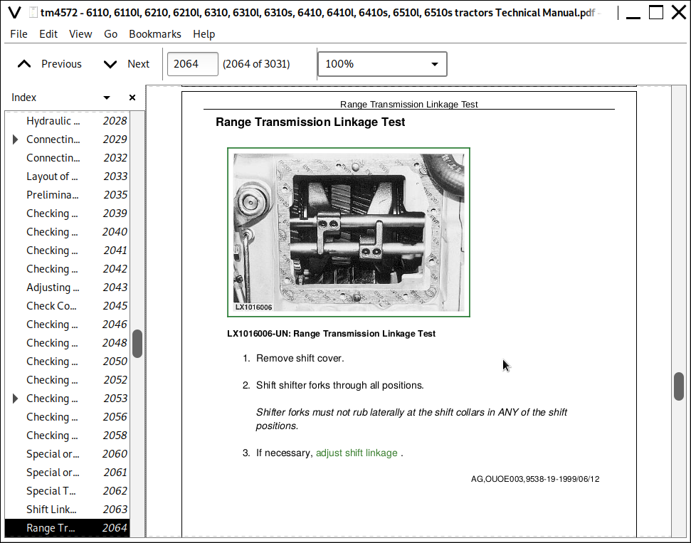
Range Transmission Linkage Test
Adjusting Range Box Shifting
Gear Transmission Linkage Test
Adjusting Shift Linkage at Gear Transmission
Adjusting Neutral Start Switch
Checking Neutral Start Switch
Adjusting the Shift Linkage and Parking Lock
Clutch Pedal Adjustment
Group 20: SyncroPlusSyncroPlus is a trademark of Deere & Company. Transmission Operation
Layout of 12-Speed Transmission
Layout of 12-Speed Transmission with Creeper
Lubrication System
Shift Operation
Synchronization
Transmission Circuit - Key to Hydraulic Schematic
Transmission Circuit - Theory of Operation
Group 20A: Perma-Clutch II
Components
Clutch Design
Power Flow, Clutch Pedal Depressed
Power Flow, Clutch Pedal Not Depressed
Transmission Oil Pump - Theory of Operation
Perma Clutch II - Legend for Hydraulic Schematic
Description of Valves and Other Hydraulic Components
Theory of Operation - Pressure Regulating and Filter Relief Valves
Theory of Operation - Clutch Pedal and Engagement Override Valves
Theory of Operation - Cooling
Group 20B: Gear Transmission
Gear Transmission Design
Power Flow in 1st Gear
Power Flow in 2nd Gear
Power Flow in 3rd Gear
Power Flow in Reverse Gear
Neutral Start Switch
Group 20C: Creeper Transmission
Layout of Creeper Transmission
Power Flow With Creeper Disengaged
Power Flow With Creeper Engaged
Group 20D: Range Transmission
Range Transmsission
Layout
Power Flow, Range A
Power Flow, Range B
Power Flow, Range C
Power Flow, Range D
Parking Lock
Section 251: Power Reverser Transmission
Group 05: Operational Checkout
Operational Checks
Group 10: Troubleshooting
Explanation of System Diagnosis
Safety Precautions
Special or Essential Tools
Specifications
Hydraulic Oil Warmup
Connecting JT07115 Hydraulic Test Kit
Connecting the Sensocontrol Testing Equipment
Layout of Test Connections and Sending Units
Preliminary Checks
Checking Gear and Range Engagement
Checking Forward/Reverse Modulation
Checking the Transmission Oil Filter
Checking System (Engagement) Pressure
Adjusting System (Engagement) Pressure
Check Components Dependent on System (Engagement) Pressure
Checking the Filter Relief Valve
Checking the Clutch Pedal Valve
Checking the Disk Clutch and Disk Brake
Checking Lubricating Oil Pressure
Checking the Clutch Cooling System
Checking the Flow Rate
Checking the Cooler Relief Valve
Group 15: Tests and Adjustments
Special or Essential Tools
Special Tool (Dealer-Manufactured)
Shift Linkage Test
Range Transmission Linkage Test
Adjusting Range Box Shifting
Gear Transmission Linkage Test
Adjusting Shift Linkage at Gear Transmission
Adjusting Reverser Control Linkage
Adjusting the Shift Linkage and Parking Lock
Clutch Pedal Adjustment
Group 20: Power Reverser Transmission Operation
Design
Transmission Circuit - Theory of Operation
Group 20A: Power Reverser Module
Components
Design and Powerflow
Power Reverser Module - Sectional View
Theory of Operation - Transmission Oil Pump
Valves and Other Hydraulic Components
Power Reverser - Legend for Hydraulic Circuit Diagram
Description of Valves and Other Hydraulic Components
Theory of Operation - Pressure Regulating and Filter Relief Valves
Theory of Operation - Forward/Reverse Modulation
Theory of Operation - Clutch Pedal Valve
Theory of Operation - Engagement Override Valve
Theory of Operation - Cooling
Group 20B: Gear Transmission
Illustration of Gear Transmission
Design and Powerflow
Section 255: Transmission
Group 05: Operational Checkout
Preliminary Checks
Operational Checkout
Group 10A: Troubleshooting PowrQuad PowrQuad is a trademark of Deere & Company. Transmission
Use Step-By-Step Hydraulic Diagnostic Charts
Special or Essential Tools
Connecting the SensoControl Testing Equipment
Service Equipment and Tools
Other Material
Observe Safety Precautions
Avoid High-Pressure Fluids
General Information on Diagnostics
Notes on the Diagnostic Program
Service Code List (RCU)
Diagnostic Address List (RCU)
Calibration Address List (RCU)
Calibrating the RCUReverser Control Unit (electronic control unit for electrical reverser control)
Adjust for Correct Pressure and Temperature References
Shortened Diagnostic Procedure
Test-Driving the Tractor
Troubleshooting System Test
Major System Checks
Additional Troubleshooting Test Procedures
Group 10B: Troubleshooting Autoquad II Transmission
Special or Essential Tools
General Information on Diagnostics
Notes on the Diagnostic Program
Service Code List (PEC) - Transmission
Diagnostic Address List (PEC) - Transmission
List of Calibratable Addresses (PEC) - Transmission
Group 15: Tests and Adjustments
Reverser Control Linkage Adjustment
Adjusting Shifter and Parking Lock - Reverser Control on Shift Console
Adjusting the Shift Linkage and Parking Lock - Reverser Control on Steering Column
Shifter and Parking Lock Adjustment
Clutch Pedal Adjustment
Transmission System Pressure Check
Group 20A: PowrQuadPowrQuad is a trademark of Deere & Company. Transmission Operation
PowrQuadPowrQuad is a trademark of Deere & Company. Transmission Layout
PowrQuadPowrQuad is a trademark of Deere & Company. Housings
Planetary Operation
Air Pump
Transmission Oil Pump
Clutch Oil Manifold
Reverse Brake Housing
Forward/Reverse Controls
Hydraulic Schematic - Mechanical Reverser Control
Hydraulic Schematic - Electrical Reverser Control
Filter Relief Valve
Pressure Regulating Valve
Forward-Reverse Modulation
EOV Circuit (With Mechanical Reverser Control)
Theory of Operation - Electrical Reverser Control
Reverse Drive Lever
Park Switch
Valve Housing on PowrQuad PowrQuad is a trademark of Deere & Company. Module
Relays
RCURCU = Reverser Control Unit
Detail of Hydraulic Circuit Diagram (Simplified)
Speed Control Circuit
Speed Modulation
Clutch Cooling Components
Oil Cooler
Cooling Valve
FWD-REV Cooling Control Valve
Cooler and Lube Circuits
Module Lube
Module Lube Flow Paths
Oil Cooler
Test Ports and Sending Units - With Mechanical Reverser Control
Test Ports and Sending Units - With Electrical Reverser Control
Group 20B: Autoquad II Transmission Operation
PowrQuad Module
PowrQuad and AutoQuadII Transmissions
Comparison of Transmission Versions
AutoQuad II Transmission Components
Description of PEC
Electric Shifting
Automatic Speed Matching
Automatic Shifting
Group 20C: Creeper Transmission
Creeper Transmission Operation
Power Flow With Creeper Transmission Engaged
Group 20D: Range Box
Design (16-Speed Transmission)
Design (20-Speed Transmission)
Design (24-Speed Transmission)
Power Flow in Range A (16-Speed Transmission)
Power Flow in Range B (16-Speed Transmission)
Power Flow in Range C (16-Speed Transmission)
Power Flow in Range D (16-Speed Transmission)
Power Flow in Range A (20- and 24-Speed Transmissions)
Power Flow in Range E (20- and 24-Speed Transmissions)
Power Flow in Range F (24-Speed Transmission)
Parking Lock
Section 256: Drive Systems (Except Transmission)
Group 05: Operational Checkout
Checking Rear PTO
Checking Front PTO
Group 10: Troubleshooting
Front Wheel Drive
Differential
Hydraulic Pump Drive
Final Drives
Rear PTO
Front PTO
Group 15: Tests
Safety Precautions
Special or Essential Tools
Connecting the Sensocontrol Testing Equipment
Specifications
Hydraulic Oil Warmup
Testing Front Wheel Drive Clutch System Pressure
Testing Hydraulic Differential Lock System Pressure
Testing the Rear PTO
Front PTO Check
Group 20A: Front Wheel Drive Clutch
Design
Oil and Power Flows With Front-Wheel Drive Engaged
Oil and Power Flows With Front-Wheel Drive Disengaged
Group 20B: Differential
Design
Power Flow When Moving Straight Ahead
Power Flow When Cornering
Oil Flow With Differential Lock Engaged
Oil Flow With Differential Lock Disengaged
Group 20C: Final Drives
Description
Group 20D: Rear PTO
Description of Rear PTO Options
PTO Modulating Valve and Solenoid Valve
Operation of PTO Clutch and Brake
PTO Power Flow (540 RPM)
PTO Power Flow (540/1000 RPM, Reversible)
Group 20E: Front PTO
Front PTO Operation
Counterclockwise-Rotating Seen in the direction of travel Front PTO - Sectional View
Independent Hydraulic Circuit
Oil Cooler
Modulating Valve and Solenoid
Hydraulic Pump
Section 260: Steering and Brakes
Group 05: Operational Checkout
Checking the Steering
Group 10: Troubleshooting
Hydrostatic Steering
Group 15: Tests and Adjustments
Special or Essential Tools
Specifications
Testing Leaf Springs of Steering Valve
Checking Steering System for External Leakage
Steering System Internal Leak Check
Steering Unit Leak Check
Steering Valve Hydraulic Connections
Testing and Adjusting Shock Valves
Bleeding the Brakes
Group 20A: Hydrostatic Steering
Description of Steering Valve
Operation of Metering Unit
Oil Flow In Steering System
Oil Flow - Neutral Position
Oil Flow - Emergency Steering
Group 20B: Hydraulic Brakes
Power Brake Valve
Brake Valve - Sectional View
Hydraulic System Schematic
Oil Flow to Brake Valve
Oil Flow During Braking
Oil Flow During Braking (Hydraulic Pump Not Working)
Rear Brake Operation
Section 270: Hydraulic System
Group 05: Operational Checks
Explanation of Operational Checks
Safety Precautions
Operational Checks
Operational Checks on Rockshaft Control
Group 10: System Diagnosis
Troubleshooting Notes
Safety Precautions
Special or Essential Tools
Connecting Test Equipment - Test Ports
Hydraulic Oil Warmup
Test Specifications
System Diagnosis in Hydraulic System
Information on System Diagnosis
Test Result LOG - Hydraulic System
Group 15: Tests and Adjustments
Explanation of the Hydraulic Tests
Safety Precautions
Special or Essential Tools
Service Equipment and Tools
Hydraulic Oil Warmup
Lube Oil Pressure of Charge Pump
Hydraulic Pump System Pressure Test and Adjustment
Adjusting Hydraulic Pump Pressure and Flow Controller
Checking Load Sense Pressure (Pilot Pressure)
Checking the Load-Sensing Valve
Differential Pressure (Dynamic)
Causes of Internal Leaks
Hydraulic System - Remedy for Missing Shuttle Valve
Check for Leaks at Valve Spools
Diagnosing Faults at the Selective Control Valves
Diagnosing Faults at Independent Control Valves
Checking Pressure Relief Valve of Rockshaft
Charge Oil Pump - Volume
Hydraulic Pump
General Information on Diagnostics
Testing and Adjusting the Control Units
Testing, Calibrating and Adjusting the Hitch Control Unit (HCU)
Hitch Troubleshooting Tips
Identification of Hitch Controls
Test Sequence - Rockshaft
HCU service code list - rockshaft
Diagnostic address list (HCU) - rockshaft
Calibration (HCU) - rockshaft
Quick Reference, Calibration (HCU) - Rockshaft
Sway dampening, enabling on HCU (rockshaft)
Additional Checks
Checking for Leaks at the Rockshaft Valve
Checking the Stepper Motor and Rockshaft Valve
Centering the Stepper Motor
Checking Depth to Which Raising and Lowering Valves are Screwed In
Checking the Position Sensor
Checking and Adjusting the Draft Sensor
Checking, Calibrating and Adjusting the Electrical Control for Independent Control Valves (PEC)
Armrest-Integrated Multi-Function Lever
Test Procedure - Independent Control Valves
PEC Service Code List - Independent Control Valves
Diagnostic Address List (PEC) - Independent Control Valves
Calibration (PEC) - Independent Control Valves
Quick Reference, Calibration (PEC) - Independent Control Valves
Enabling Function 2 or 3 (PEC) - Independent Control Valves
Checking the Stepper Motor and Stepper Motor Driver
Group 20: Hydraulic System
Hydraulic Symbols (ISO 1219)
Hydraulic System Description
Hydraulic System Operation
Hydraulic System - Symbolic View
Hydraulic System - Schematic View
Hydraulic System - Three-Dimensional View
Group 20A: Charge Oil Pump
Charge Pump - Description and Theory of Operation
Group 20B: Hydraulic Pumps
Description of Hydraulic Pump
Layout of Oil Lines
Hydraulic Pump - Theory of Operation
Operating Modes
Group 20C: Valves, Oil Cooler and Filter
Hydraulic Oil Filter With Filter Relief Valve
Oil Cooler
Primary Filter
Shuttle Valve Description
Shuttle Valve Operation
Main Valve Block with Priority Valve
Priority Valve Operation
Group 20D: Rockshaft
Rockshaft Description
Rockshaft Operation
Rockshaft Valve - Theory of Operation
Position Sensor
Draft Sensor
Control Console
Hitch Control Unit (HCU)
Direct Control of Rockshaft
Group 20E: SCVs and Couplers
Selective Control Valves
200 Series Selective Control Valve - Neutral Position
200 Series Selective Control Valve - Extend Position
200 Series Selective Control Valve - Retract Position
200 Series Selective Control Valve - Float Position
300 Series Selective Control Valve - Neutral Position
300 Series Selective Control Valve - Extend Position
300 Series Selective Control Valve - Retract Position
300 Series Selective Control Valve - Float Position
Couplers
Endplates on SCV Units - Overview
Group 20F: Independent Selective Control Valve
Description
Independent Control Valve (mechanical controlled) - Sectional View
Independent Control Valve (Electrically Actuated) - Sectional View
Oil Flow Through the Independent Control Valve
Right Special End Cap
Section 280: Miscellaneous
Group 05: TLS Front Axle Operational Checkout
Operational Checkout Notes
Safety Measures
Operational Check
Monitoring and Warning Devices
Group 10: TLS Front Axle Troubleshooting
Special Tools
General Information on Diagnostics
Safety Measures
System Diagnosis (Troubleshooting)
Troubleshooting
Notes on the Diagnostic Program
Explanation, System Start - System Fault
Explanation of Monitoring and Warning Devices
Test Sequence-Troubleshooting
Explanation of Diagnostics Address 01
Explanation of Diagnostics Address 02
Service Code List (SFA)
Diagnostic Address List (SFA)
Calibrating the FWD axle with TLS
Group 15: TLS Front Axle Tests and Adjustments
Explanation of Tests and Adjustments
Safety Measures
Special or Essential Tools
Specifications
Relieve Pressure from Suspended MFWD Axle Hydraulic System
Bleeding the Hydraulic System
Check and Charge Suspended MFWD Axle Accumulators
Group 20: TLS Front Axle Operation
6110 to 6410 Tractor Suspension
6110 to 6410 Tractor Components
Description-Level Control
Operation
Hydraulic Circuit Schematic-Suspension Function
Hydraulic Circuit Schematic-Level Control (Up)
Hydraulic Circuit Schematic-Level Control (Down)
Electronic Control Unit (SFA)
Position Sensor
Section 290: Cab
Group 05: Operational Checks
Before You Start
Group 10A: Air Conditioning - System Diagnosis
Safety At Work
Handling Refrigerant
Safety Equipment
In An Emergency
Storage of Refrigerant Containers
R134A Refrigerant
Important Note
Service Equipment and Tools
Other Materials Specifications
Specifications
Air Conditioning System Diagnosis
Group 10B: Ventilation and Heater - System Diagnosis
Check Heading
Group 10C: Operator's Seat - System Diagnosis
Diagnosis, MSG95 Operator's Seat
Weight and Height Setting not Functioning in Upward Direction
Weight and Height Setting not Functioning in Downward Direction
Spring Collapses after a Short Interval
Spring Can Be Lowered Properly, but Does not Pump Up from the Lowest Position
Spring Can Be Pumped Up to the Uppermost Position, but Does not Deflate
Spring Can Be Pumped Up and Lowered, but Returns to its Original Height
Group 20A: Air Conditioning System - Theory of Operation
Principle of Heat Exchange
R134A Refrigerant
Refrigerant Circuit Diagram
Description of How Refrigerant Circuit Functions
Compressor
Condenser
Receiver-Drier
Expansion Valve
Thermostat Switch
Evaporator
High/Low Pressure Switch
Temperature Control and Compressor Switch
Group 20B: Ventilation and Heater - Theory of Operation
Check Heading
Section 299: Special Tools (Dealer Fabricated)
Group 05: Special Tools (Dealer Fabricated)
Holding Tool
DFRW2-Needle Valve Test Hose Assembly
DFRW85-Reverse Brake Test Plate
DFLX10 and DFLX11 -Tap-Out Harnesses
DFLX12 - 11-BIT- and 29-BIT- CAN BUS Special Tool
DFLX14 –– Solenoid Test Harness
John Deere Tractors 6110, 6110l, 6210, 6210l, 6310, 6310l, 6310s, 6410, 6410l, 6410s, 6510l, 6510s Diagnosis and Tests Service Technical Manual (TM4572)
![]()