
John Deere Self-Propelled Sprayer 4710 Repair Service Manual (TM1861)
Complete Repair Service Manual for John Deere Self-Propelled Sprayer 4710 (SN. from 004001), with technical information to maintain, repair, and rebuild like professional mechanics.
John Deere Self-Propelled Sprayer 4710 workshop Repair manual includes:
* Numbered table of contents easy to use so that you can find the information you need fast.
* Detailed sub-steps expand on repair procedure information
* Numbered instructions guide you through every repair procedure step by step.
* Troubleshooting and electrical service procedures are combined with detailed wiring diagrams for ease of use.
* Notes, cautions and warnings throughout each chapter pinpoint critical information.
* Bold figure number help you quickly match illustrations with instructions.
* Detailed illustrations, drawings and photos guide you through every procedure.
* Enlarged inset helps you identify and examine parts in detail.
TM1861 - John Deere Self-Propelled Sprayer 4710 Technical Manual - Repair.PDF
TM1861 - John Deere Self-Propelled Sprayer 4710 Technical Manual - Repair.EPUB
Total Pages: 1,122 pages
File Format: PDF/EPUB/MOBI/AZW (PC/Mac/Android/Kindle/iPhone/iPad; bookmarked, ToC, Searchable, Printable)
Language: English
MAIN SECTIONS
Foreword
General Information
Safety
General Information
Fuels and Lubricants
Engine
Component Removal and Installation
Fuel, Air Intake, and Cooling Systems
Throttle Controls
Diesel Fuel System
Engine Cooling System
Electrical
Connector Repair
Charging Circuit
Starting Circuit
Switches and Relays
Monitoring Systems and Sensors
Accessory Connectors
Convenience and Accessory Components
Retractable Ladder
Power Train Repair
Remove and Install Hydrostatic Components
Hydrostatic Drive Repair
Planetary Hub Repair
Steering and Brakes
Steering Column
Remove and Install Steering Valves
Steering Cylinder
Brakes
Suspension and Tread Adjust Repair
Suspension
Tread Adjust Valves
Tread Adjust Cylinders
Tread Adjust Shim Pads
Hydraulic System
Hydraulic Pump-Eaton
Hydraulic Valves
Boom Hydraulic Cylinders
Hydraulic Oil Cooler
Hydraulic Reservoir
Accumulator
Solution Spray System
Nozzle Repair
Solution Tank
Solution Pump
Solution Control Valves
132 L (35 Gal) Foam Marker System
132 L (35 Gal) Foam Marker System Repair
On Board Air System
Operator Station
Component Removal and Installation
Controls
Air Conditioning System
Heating System
Air Suspension Seat
Cab Door and Windshield
Boom Repair
Boom Repair
Dealer Fabricated Tools
tm1861 - 4710 Self-Propelled Sprayer Repair
Table of Contents
Foreword
Section 10: General Information
Group 05: Safety
Follow Safety Instructions
Recognize Safety Information
Understand Signal Words
Perform Service Safely
Park Machine Safely
Handle Fluids Safely—Avoid Fires
Prevent Battery Explosions
Prepare for Emergencies
Protect Against High Pressure Spray
Prevent Acid Burns
Wear Protective Clothing
Handle Chemical Products Safely
Avoid Contact with Agricultural Chemicals
Clean Vehicle of Hazardous Pesticides
Support Machine Properly
Service Machines Safely
Practice Safe Maintenance
Avoid Harmful Asbestos Dust
Work In Ventilated Area
Work in Clean Area
Remove Paint Before Welding or Heating
Avoid Heating Near Pressurized Fluid Lines
Avoid High-Pressure Fluids
Service Tires Safely
Service Cooling System Safely
Illuminate Work Area Safely
Replace Safety Signs
Use Proper Lifting Equipment
Use Proper Tools
Construct Dealer-Made Tools Safely
Decommissioning — Proper Recycling and Disposal of Fluids and Components
Live With Safety
Group 10: General Information
Specifications
Dimensions—18.3 m (60 ft) Boom
Dimensions—24.4 m and 27.4 m (80 and 90 ft) Boom
Dimensions—All Machines
Dimensions—All Machines
Identification Numbers
Face Seal Fittings Assembly and Installation—All Pressure Applications
Metric Face Seal Fitting Torque Chart—Standard Pressure Applications
Metric Face Seal Fitting Torque Chart—High Pressure Applications
SAE Face Seal Fitting Torque Chart—Standard Pressure Applications
SAE Face Seal Fitting Torque Chart—High Pressure Applications
Four Bolt Flange Fittings Assembly and Installation—All Pressure Applications
SAE Four Bolt Flange Cap Screw Torque Values—Standard Pressure Applications
SAE Four Bolt Flange Cap Screw Torque Values—High Pressure Applications
External Hexagon Port Plug Torque Chart
Metric Bolt and Screw Torque Values
Unified Inch Bolt and Screw Torque Values
Glossary of Terms
Group 15: Fuels and Lubricants
Diesel Fuel
Testing Diesel Fuel
Handling and Storing Diesel Fuel
Lubricity of Diesel Fuel
Diesel Engine Coolant (engine with wet sleeve cylinder liners)
Testing Diesel Engine Coolant
Supplemental Coolant Additives
Operating in Warm Temperature Climates
Additional Information About Diesel Engine Coolants and John Deere LIQUID COOLANT CONDITIONER
Diesel Engine Break-In Oil — Non-Emissions Certified and Certified Tier 1, Tier 2, Tier 3, Stage I, Stage II, and Stage III
Diesel Engine Oil — Non-Emissions Certified and Certified Tier 1 and Stage I
Extended Diesel Engine Oil Service Intervals — Non-Emissions Certified and Certified Tier 1 and Stage I
Hydrostatic/Hydraulic Drive Oil
Planetary Hub Oil
Grease
Suspension and Steering Grease
Alternative and Synthetic Lubricants
Lubricant Storage
Section 20: Engine
Group 05: Component Removal and Installation
Repair Engine—Use CTM104
Essential or Recommended Tools
Specifications
Clean Vehicle of Hazardous Pesticides
Remove Engine
Install Engine
Section 30: Fuel, Air Intake, and Cooling Systems
Group 05: Throttle Controls
Remove and Install Throttle Actuator
Group 10: Diesel Fuel System
Specifications
Remove Fuel Tank
Clean and Inspect Fuel Tank
Install Fuel Tank
Group 15: Engine Cooling System
Essential or Recommended Tools
Specifications
Clean Vehicle of Hazardous Pesticides
Test Radiator and Cap
Remove Hydraulic Oil Cooler and A/C Condenser Assembly
Install Hydraulic Oil Cooler and A/C Condenser Assembly
Remove Radiator
Install Radiator
Inspect Belt Tensioner
Replace Belt Tension Mechanism
Section 40: Electrical
Group 05: Connector Repair
Connector Identification and Functions
Essential or Recommended Tools
Using High-Pressure Washers
Service Parts Kits
Replace SURE-SEAL Connectors
Replace CPC™, Large Mate-N-Lok®, and Metrimate® Pin Type Connectors
Replace CPC™ Blade Type Connectors
Replace Small Mate-N-Lok® Socket Connector
Replace Small Mate-N-Lok® Pin Connector
Replace Weather Pack™ Connector
Replace SURE-SEAL® Connector with Weather Pack™ Connector
Remove Connector Body from Blade Terminals
Install WEATHER PACK Contact
Repair YAZAKI Connectors
Replace Molex MINI-FIT Connector
Group 10: Charging Circuit
Repair Alternator—Use CTM77
Disconnect Electrical Circuit
Remove and Install Alternator
Group 15: Starting Circuit
Essential or Recommended Tools
Specifications
Repair Starter—Use CTM77
Remove and Install Starter Motor
Replace Starter Circuit Relay
Replace and Adjust Neutral Start Switch
Group 20: Switches and Relays
Disconnect Electrical Circuit
Replace A/C High and Low Pressure Switches (S.N. —4000)
Replace A/C High/Low Pressure Switch (S.N. 4001—)
Side Console Switches
Replace Side Console Switches
Replace Dome Light Switch
Replace Cab Door Light Switch
Replace Seat Raise/Lower Switch
Replace Starting Aid Switch
Replace Ignition Switch
Replace A/C Deicing Switch and Blower Motor Resistor
Replace Boom Fold/Level Switch
Replace Thermo Starting Aid and Relay
Load Center Fuses
Load Center Relays and Diodes
Replace Remote Throttle Switch
Replace Remote Solution Pump Switch
Replace Remote Ladder Switch (S.N. —4000)
Replace Remote Ladder Switch (S.N. 4001—)
Ladder Actuator Relay
18.3 M (60 Ft) Boom Relays
24.4 M and 27.4 M (80 and 90 Ft) Boom Relays
Group 25: Monitoring Systems and Sensors
Other Material
Specifications
Disconnect Electrical Circuit
Replace Turn Signal Indicator Bulbs
Replace Steering Column Mini-Pod
Replace Chassis Computer Unit/Spray Rate Control Unit (CCU/SRC)
Replace Engine Speed Sensor
Replace Engine Oil Pressure Sensor
Replace Engine Coolant Temperature Sensor
Replace Air Filter Restriction Indicator Sensor
Replace Hydraulic Oil Temperature Sensor
Replace Wheel Speed Sensor
Adjust Wheel Speed Sensor
Replace Fuel Level Sender
Replace Solution Pressure Sensor
Remove and Install Flowmeter Sensor
Replace Active Terminator
Replace Passive Terminator
Group 30: Accessory Connectors
Replace Three-Pin Accessory Outlets
Replace and Adjust Field Lights
Group 35: Convenience and Accessory Components
Replace Circulation Blower Motor
Remove Air Quality (AQS) Pressurizer Blower Motor
Replace Wiper Motor
Replace Windshield Washer Pump
Replace Seat Air Compressor Motor
Remove Radio and Speakers
Group 40: Retractable Ladder
Service Parts Kits
Remove and Install Ladder Actuator
Disassemble, Inspect and Assemble Ladder Actuator
Section 50: Power Train Repair
Group 05: Remove and Install Hydrostatic Components
Essential or Recommended Tools
Service Equipment and Tools
Other Material
Specifications
Emergency Tow Procedure
Start-Up Procedure After Hydrostatic Repair
Flushing Hydrostatic Drive System
Remove Hydrostatic Drive Pump
Install Hydrostatic Drive Pump
Replace Hydrostatic Drive Pump Isolators (S.N. 4001—)
Remove and Install Drive Shaft and Flywheel
Inspect Drive Shaft
Remove Hydrostatic Drive Motor
Install Hydrostatic Drive Motor
Remove Planetary Hub
Install Planetary Hub
Remove, Install and Adjust Hydrostatic Control Cable
Group 10: Hydrostatic Drive Repair
Essential or Recommended Tools
Service Equipment and Tools
Other Material
Specifications
Clean Vehicle of Hazardous Pesticides
Remove and Install Hydrostatic Pump Shaft Seal
Replace Hydrostatic Pump Cartridge Valves
Replace Hydrostatic Pump Charge Pressure Relief Valve
Repair Charge Pump
Remove and Install Hydrostatic Pump Control Valve
Remove and Install Control Valve Neutral Start Switch
Adjust Control Valve Eccentric Plug
Disassemble Hydrostatic Drive Pump
Inspect and Repair Hydrostatic Drive Pump
Assemble Hydrostatic Drive Pump
Disassemble Hydrostatic Drive Motor
Assemble Hydrostatic Drive Motor
Group 15: Planetary Hub Repair
Determine Which Planetary Hub Repair Procedure To Use
Essential or Recommended Tools
Service Equipment and Tools
Other Material
Specifications
Clean Vehicle of Hazardous Pesticides
Disassemble Planetary Hub—Style A
Assemble Planetary Hub—Style A
Disassemble Planetary Hub—Style B
Assemble Planetary Hub—Style B
Section 60: Steering and Brakes
Group 05: Steering Column
Essential or Recommended Tools
Specifications
Repair Steering Column (S.N. —4000)
Repair Steering Column (S.N. 4001—)
Bleed Steering System
Group 10: Remove and Install Steering Valves
Specifications
Remove Steering Valve (S.N. —4000)
Remove Steering Valve (S.N. 4001—)
Remove and Install Steering Valve with Auto Trac (S.N. 4001—)
Repair Steering Valve (S.N. —4000)
Repair Steering Valve (S.N. 4001—)
Install Steering Valve (S.N. —4000)
Install Steering Valve (S.N. 4001—)
Replace Shuttle Valve (S.N. —4000)
Replace Shuttle Valve (S.N. 4001—)
Toe Control Valve Hose Routing Diagram Without Auto Trac
Toe Control Valve Hose Routing Diagram with Auto Trac
Remove and Install Toe-Control Valve (If Equipped)
Group 15: Steering Cylinder
Service Parts Kit
Specifications
Remove and Install Steering Cylinder
Repair Steering Cylinder (S.N. —4000)
Repair Steering Cylinder (S.N. 4001—)
Check Front Axle Toe-In
Adjust Front Axle Toe-In
Group 20: Brakes
Other Material
Specifications
Inspect Service Brake System Components
Disassemble, Inspect and Assemble Service Brake Linkage
Remove and Install Service Brake Valve
Remove Service Brake Caliper
Disassemble, Inspect and Assemble Service Brake Caliper
Install Service Brake Caliper
Start-Up Procedure After Brake System Repair
Section 61: Suspension and Tread Adjust Repair
Group 05: Suspension
Essential or Recommended Tools
Other Material
Specifications
Clean Vehicle of Hazardous Pesticides
Replace Suspension Bushings and Seals
Adjust Front and Rear Air Spring Assemblies
Remove and Install Air Spring Leveling System Control Valve
Air Spring Leveling System Linkage
Group 10: Tread Adjust Valves
Essential or Recommended Tools
Specifications
Service Parts Kit
Tread Adjust Valve Block
Remove and Install Tread Adjust Valve Block
Replace Vickers Control Valve Coil(s)
Replace Tread Adjust Valve
Remove, Inspect and Install Manifold Check Valve and Pilot Piston
Group 15: Tread Adjust Cylinders
Essential or Recommended Tools
Other Material
Service Parts Kit
Remove and Install Hydraulic Tread Adjust Cylinders
Disassemble Tread Width Adjustment Cylinder (Snap Ring Retention)
Inspect Cylinder Barrel
Tread Width Adjustment Cylinder Components (Snap Ring Retention)
Assemble Tread Width Adjustment Cylinder (Snap Ring Retention)
Group 20: Tread Adjust Shim Pads
Essential or Recommended Tools
Other Material
Replacing Top Tread Adjust Shim Pads
Replacing Bottom Tread Adjust Shim Pads
Section 70: Hydraulic System
Group 05: Hydraulic Pump—Eaton
Service Parts Kit
Specifications
Clean Vehicle of Hazardous Pesticides
Relieve Hydraulic System Pressure
Remove and Install Hydraulic Pump
Disassemble and Assemble Hydraulic Pump
Remove and Install Hydraulic Pump Compensator
Repair Hydraulic Pump Compensator
Group 10: Hydraulic Valves
Essential or Recommended Tools
Other Material
Specifications
Service Parts Kit
18.3 m (60 Ft) Boom Valve
24.4 m and 27.4 m (80 and 90 ft) Boom Valve
24.4 m and 27.4 m (80 and 90 ft) Roll Bias Boom Valve (Optional)
Disassemble, Inspect and Assemble 24.4 m and 27.4 m (80 and 90 ft) Roll Bias Boom Valve
Remove and Install Boom Control Valve
Boom Control Valve General Information
Disassemble, Inspect and Assemble Boom Control Valve
Replace Priority Valve
Disassemble, Inspect and Assemble Priority Valve (S.N. 4001—)
Remove and Install Proportional Valve
Disassemble and Assemble Proportional Valve
Remove and Install Reverse Boost, Load Sense Jam and Shuttle Valves (S.N. —4000)
Remove and Install Reverse Boost, Load Sense Jam and Shuttle Valves (S.N. 4001—)
Exploded View Of Reverse Boost, Load Sense Jam and Shuttle Valves (S.N. 4001—)
Replace Proportional Valve
Group 15: Boom Hydraulic Cylinders
Other Material
Specifications
Service Parts Kit
Remove and Install 18.3 m (60 ft) Boom Lift Cylinders
Remove and Install 24.4 m and 27.4 m (80 and 90 ft) Boom Lift Cylinders
Remove and Install 18.3 m (60 ft) Boom Leveling Cylinders
Remove and Install 24.4 m and 27.4 m (80 and 90 ft) Boom Leveling Cylinder (S.N. —4000)
Remove and Install 18.3 m (60 ft) Boom Folding Cylinders
Remove and Install 24.4 m and 27.4 m (80 and 90 ft) Boom Folding Cylinders (S.N. —4000)
Remove and Install 24.4 m and 27.4 m (80 and 90 ft) Boom Fold Cylinder (S.N. 4001—)
Disassemble and Assemble Boom Lift Cylinder
Disassemble and Assemble Outer Folding Cylinder (S.N. —4000)
Disassemble and Assemble Outer Folding Cylinder (S.N. 4001—)
Disassemble and Assemble Roll Bias Cylinder
Disassemble and Assemble Boom Tilt Cylinder
Disassemble and Assemble Inner Boom Fold Cylinder (S.N. —4000)
Disassemble and Assemble Boom Inner Fold Cylinder (S.N. 4001—)
Disassemble and Assemble Below Horiz. Tilt Cylinder
Group 20: Hydraulic Oil Cooler
Hydraulic Oil Cooler/Air Conditioning Condenser
Group 25: Hydraulic Reservoir
Specifications
Remove Hydraulic Reservoir
Install Hydraulic Reservoir
Clean Hydraulic Reservoir Strainers
Group 30: Accumulator
Service Equipment and Tools
Specifications
Remove and Install Accumulator
Charge Accumulator (Serial No. —2253)
Charge Accumulator (Serial No. 2254— )
Section 80: Solution Spray System
Group 05: Nozzle Repair
Decontaminate Spray Equipment
Clean Vehicle of Hazardous Pesticides
Cleaning Hardi Single Nozzle Bodies and Check Valves
Cleaning Hardi Triplet Nozzle Bodies and Check Valves
Cleaning TEEJET TEEJET is a trademark of Spraying System Co. Single Nozzle Bodies and Check Valves
Cleaning TEEJET Triplet Nozzle Bodies
Cleaning SPRAY MASTER Single Nozzle Bodies and Check Valves
Cleaning SPRAY MASTER Triple Nozzle Bodies
Group 10: Solution Tank
Specifications
Service Equipment and Tools
Other Material
Decontaminate Spray Equipment
Flush Solution Tank and Spray System
Remove and Install Solution Tank (S.N. —4000)
Remove and Install Solution Tank (S.N. 4001—)
Remove and Install Agitation Nozzles
Group 15: Solution Pump
Service Equipment and Tools
Other Material
Specifications
Decontaminate Spray Equipment
Remove Solution Pump and Motor (S.N. —4000)
Remove Solution Pump and Motor (S.N. 4001—)
Solution Pump Exploded View
Repair Solution Pump
Repair Solution Pump Hydraulic Motor
Install Solution Pump and Motor (S.N. —4000)
Install Solution Pump and Motor (S.N. 4001—)
Group 20: Solution Control Valves
Other Material
Specifications
Decontaminate Spray Equipment
Replace Solution Control Valves (S.N. —4000)
Disassemble and Assemble Fittings
Repair Check Valves and Strainers
Replace Solution Control Valves (S.N. 4001—)
Exploded View— Flowmeter Assembly
Remove and Install Flowmeter Assembly
Replace Flowmeter
Remove and Install Flowmeter Sensor
Remove and Install Boom Section Shut-Off Valves
Section 81: 132 L (35 Gal) Foam Marker System
Group 05: 132 L (35 Gal) Foam Marker System Repair
Specifications
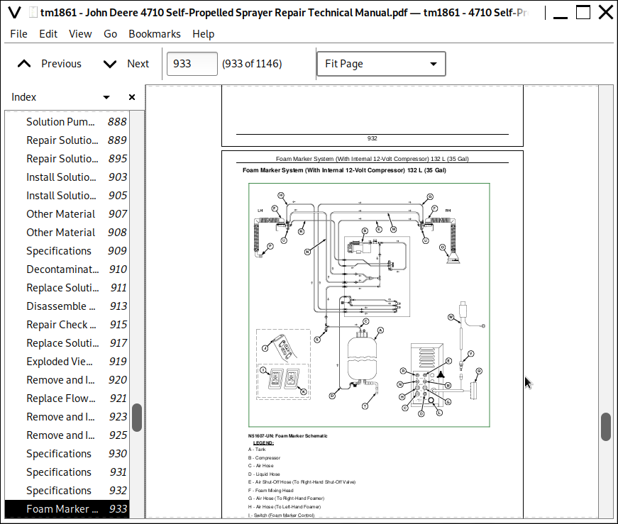
Foam Marker System (With Internal 12-Volt Compressor) 132 L (35 Gal)
Repair Foam Marker Tubes
Replace Foam Marker Fuses
Repair Tank
Repair Foam Mixing Head
Repair Compressor
Repair Foam Collectors
Repair Foam Marker Quick Fill
Fittings
Disassemble, Inspect and Assemble Foam Mixing Head
Group 10: On Board Air System
Specifications
Service Part Kit
On Board Air Compressor (S.N. —4000)
On Board Air Compressor (S.N. 4001—)
Remove On Board Air Compressor
Disassemble And Inspect On Board Air Compressor
Assemble On Board Air Compressor
Install On Board Air Compressor
Remove and Install On Board Air Dryer (S.N. —4000)
Repair On Board Air Dryer
Disassemble and Assemble Unloader Valve (S.N. 4001—)
Section 90: Operator Station
Group 05: Component Removal and Installation
Essential or Recommended Tools
Specifications
Clean Vehicle of Hazardous Pesticides
Remove Cab
Install Cab
Group 10: Controls
Remove and Replace Hydro Control Lever Assembly
Remove, Install, and Adjust Temperature Control Cable
Group 15: Air Conditioning System
Essential or Recommended Tools
Other Material
Service Parts Kits
Specifications
Hose and Tubing O-Ring Connection Torques
System Information
Diagram - Air Conditioning System
Air Conditioning System Fittings—Reference Chart
Discharge Air Conditioning System
Flush Compressor
Flush Evaporator
Flush Evaporator (Through Expansion Valve)
Flush Condenser
Purge Air Conditioning System
Evacuate Air Conditioning System
Charge Air Conditioning System
Refrigerant Oil Information
Check Refrigerant Oil Charge
Determine Correct Refrigerant Oil Charge
Add Refrigerant Oil to System
Add Oil to Pressurized System
Remove and Install Compressor
Test Volumetric Efficiency
Test Shaft Seal Leakage
Disassemble and Assemble Compressor Clutch
Check Clutch Hub Clearance
Inspect Compressor Manifold
Disassemble, Inspect and Assemble Compressor
Remove and Install Compressor Relief Valve
Remove and Install Expansion Valve
Replace Receiver-Dryer
Remove Hydraulic Oil Cooler/Air Conditioning Condenser
Install Hydraulic Oil Cooler/Air Conditioning Condenser
Leak Test Hydraulic Oil Cooler/Air Conditioning Condenser
Remove Air Quality System Module
Remove and Install Heater Core or Evaporator
Leak Test Air Quality System Module
Install Air Quality System Module
Group 20: Heating System
Remove Heater Control Valve
Leak Test Heater Control Valve
Install Heater Control Valve
Group 25: Air Suspension Seat
Other Material
Remove Seat from Suspension (S.N. —4000)
Remove Seat from Suspension (S.N. 4001—)
Remove Air Seat Suspension System (S.N. 4001—)
Disassemble, Inspect and Assemble Seat Air Suspension Assembly (S.N.—4000)
Operator Seat—Exploded View (S.N. 4001—)
Operator Seat Air Suspension Assembly—Exploded View (S.N. 4001—)
Disassemble and Assemble Operator's Seat AirSuspension Assembly (S.N. 4001—)
Group 30: Cab Door and Windshield
Specifications
Replace Cab Door Latch Assembly
Replace Cab Door Jaw Assembly
Replace Cab Door Interior Release Handle
Cab Door Adjustment—Step 1
Cab Door Adjustment—Step 2
Cab Door Adjustment—Step 3
Cab Door Adjustment—Step 4
Cab Door Adjustment—Step 5
Replace Windshield Glass or Seal
Section 100: Boom Repair
Group 05: Boom Repair
Essential or Recommended Tools
Specifications
Remove and Install Boom Shock Absorbers and Rubber Stops
Remove and Install Boom Roll Suspension Springs
Remove and Install Boom Rear Anti-Yaw Link
Replace Boom Anti-Yaw Link Washers
Remove and Install Yaw Rocker Cushions
Remove and Install Boom Center Roll Bearing
Section 199: Dealer Fabricated Tools
Group 05: Dealer Fabricated Tools
DFN20 Solution Pump Seal Driver
DFN21 Pump Support Fixture
DFN22 Bearing Seat Driver
DFN23 Hydrostatic Motor Seal Driver
DFNX65-A1 Eccentric Plug Adjustment Tool
DFNX65-A2 Sizing Arbor
DFNXT1—High Pressure Flange Wrench
DFNXT2—Agitation Nozzle Tool
John Deere Self-Propelled Sprayer 4710 Repair Service Manual (TM1861)
![]()