
Volvo EC45 Compact Excavators Service Repair Manual
Complete service manual for Volvo EC45 Compact Excavators, with all the shop information to maintain, diagnose, repair, and rebuild like professional mechanics.
Volvo Constructions EC45 Compact Excavators workshop service & repair manual includes:
* Numbered table of contents easy to use so that you can find the information you need fast.
* Detailed sub-steps expand on repair procedure information
* Numbered instructions guide you through every repair procedure step by step.
* Troubleshooting and electrical service procedures are combined with detailed wiring diagrams for ease of use.
* Notes, cautions and warnings throughout each chapter pinpoint critical information.
* Bold figure number help you quickly match illustrations with instructions.
* Detailed illustrations, drawings and photos guide you through every procedure.
* Enlarged inset helps you identify and examine parts in detail.
Volvo EC45 Compact Excavators Service Repair Manual.pdf
TABLE OF CONTENTS
0 - Foreword.....2
0 - GENERAL.....3
00 - DESCRIPTION; COMPLETE MACHINE.....4
Position of components.....5
Warning and information decals.....6
Caution sign - Operation and maintenance.....7
Warning sign - Open engine hood only with engine stopped.....8
Foreword.....9
Warning sign - Safety distance from the work area.....10
Warning sign - Safety distance from the movement area.....11
Caution sign - Track tension.....12
Caution sign - Diesel engine starting procedure.....13
Caution sign - Lifting the machine.....14
Caution sign - Lashing.....15
Caution sign - Emergency exit.....16
Machine identification.....17
03 - SPECIFICATIONS.....19
Tightening torques.....20
Main dimensions EC 45.....31
Load capacity tables EC 45-22.....33
Fuel; lubricant and filling capacities-56.....34
Load capacity tables EC 45.....35
Reach of the working attachment EC 45.....36
Reach EC 45.....37
Strength class 8.8 Metric coarse and fine threads.....39
Strength class 10.9 Metric coarse and fine threads.....40
UNC-threads; coarse pitch.....41
Plugs with tapered thread.....42
Tightening torques; engine-55.....43
Mechanical transmission - track gearbox.....44
Hydraulic motor 1 - travel system.....45
Fuels; lubricants and filling capacities (litres).....46
ENGINE.....47
Electrical system.....49
Power transmission.....50
Hydraulic system EC 45.....51
Slewing ring; tightening torques-27.....52
07 - STANDARD TIME.....53
Operation numbers for additional work.....54
1 - STANDARD PARTS; SERVICE.....56
16 - LUBRICANT; FUEL; OTHER FLUID.....57
Hydraulic oil.....58
Recommended lubricants.....63
Alternative fuels.....64
17 - SERVICE.....67
Service and maintenance.....68
Repairing hydraulic system.....70
Electric welding.....71
Cleanliness; braking and hydraulic system.....72
Maintenance instructions.....73
Engine air filter unit.....77
Change engine oil; replace filter.....79
Recharging of batteries.....81
Hydraulic system; replacement of hydraulic filter element.....82
Changing the hydraulic oil-.....84
Travel gear; oil change.....87
Inspection.....88
Cylinder speed.....89
Swing speed.....93
Slewing overtravel.....94
Measuring the play of the slewing bearing.....96
Travel Speed.....99
Jump starting.....101
19 - GENERAL.....103
Safety concerns everybody!.....104
General precautions.....106
Preparations for work.....109
Safety measures during operation.....112
Move and operate machine safely.....117
2 - ENGINE WITH MOUNTING AND EQUIPMENT.....119
20 - GENERAL.....120
Description-00.....121
Precautions.....123
Troubleshooting chart.....124
21 - ENGINE.....130
Specification; engine.....131
Specification; weight.....132
Specification; filling capacities.....133
Valve timing.....134
COOLING SYSTEM.....135
Tightening torques; engine.....136
Engine trouble shooting.....137
Compression pressure inspection.....139
Valves; adjusting.....141
22 - LUBRICATING SYSTEM.....143
Lubrication system; specification.....144
Lubricating system; description.....145
Removing the oil filter.....147
Installing the oil filter.....148
Removing the oil pressure switch.....149
Installing the oil pressure switch.....151
23 - FUEL SYSTEM.....152
Description.....153
Disassembling the fuel pump.....154
Installing the fuel pump.....155
Changing the fuel filter-24.....156
Bleeding the fuel system.....158
Disassembling the fuel injection line.....159
Assembling the fuel injection line.....160
Idle speed; inspection and adjustment.....161
25 - INLET & EXHAUST SYSTEM.....163
Schematic.....164
26 - COOLING SYSTEM.....165
Removing the coolant pump.....166
Removing the thermostat housing.....169
Tensioning the V-belt.....173
Changing the V-belt.....174
3 - ELECTRICAL; WARNING; INFORMATION; INSTRUMENTS.....175
30 - GENERAL.....176
Electrical system; description.....177
Electrical system; technical data.....178
Basic objects of examination.....179
Diagnostics.....180
Electric system; trouble shooting.....182
Precautions when handling plug connectors.....183
31 - BATTERY.....185
Battery; location and removal.....186
Battery; description.....188
Battery; specification.....189
32 - ALTERNATOR; CHARGE REGULATOR.....190
Tests before disassembly.....191
Removing the generator.....193
Installing the generator.....194
Disassemble the generator.....196
Assemble the generator.....202
Checking the voltage regulation.....204
Checking the performance characteristics.....205
33 - STARTING SYSTEM.....207
Starter motor; disassembly and assembly.....208
35 - LIGHTING.....210
Boom_cabin_weather roof.....211
Working headlights and main headlights; description.....214
Working headlights and main headlights; specification.....215
37 - CABLE; FUSE; RELAY.....216
Colour codes.....217
Designations of electrical components.....218
Wiring diagram; schematic drawing (part 1).....225
Wiring diagram; schematic drawing (part 2).....228
Wiring engine; schematic drawing.....231
Complete wiring diagram (part 1).....234
Complete wiring diagram (part 2).....236
Fuses for machine equipment.....239
Fuses for cabin equipment.....240
Relay.....241
38 - INSTRUMENT; SENSOR; WARNING & INFORMATION SYSTEM.....242
Electrical components (hydraulic system side part 1).....243
Electrical components (hydraulic system side part 2).....244
Electronic multi-function switch PUMA (ECU1).....245
error codes.....247
4 - POWER TRANSMISSION.....248
40 - GENERAL.....249
Fuel; lubricant and filling capacities.....250
Working principle of the travel system.....251
Technical data.....254
44 - HYDROSTATIC DRIVE.....256
Design of travel motor.....257
Design of axial piston motor.....259
Brake valve (counter balance valve).....261
Removing the travel motor.....264
Assembling the travel motor.....267
Travel motor; exploded view.....270
Travel gear; dismantling.....272
Travel gear; mounting.....281
Hydraulic motor 001; travel gear.....292
Disassembling the hydraulic motor.....295
Assembling the hydraulic motor.....308
Removing the gear motor.....321
Assembling the gear motor.....323
Hydraulic motor – slewing of superstructure.....325
Removing the oil distributor seals.....327
Assembling the oil distributor seals.....329
Removing the cylinder block.....330
Assembling the cylinder block.....332
Disassembling pistons and guide sleeves.....333
Assembling pistons and guide sleeves.....335
Removing the radial seals.....336
Assembling the radial seals.....337
Disassembling the roller bearings.....339
Assembling the roller bearings.....340
Swivel joint.....343
49 - MISCELLANEOUS.....345
Applying the brake.....346
Releasing the slewing brake.....347
Assembling the brake discs.....348
Removing the brake discs.....350
Miscellaneous.....351
5 - BRAKE.....352
53 - TRACK BRAKE.....353
Brake; description.....354
6 - STEERING.....355
60 - GENERAL.....356
Steering system; description.....357
7 - FRAME; SPRINGS; DAMPING; AXLE SUSPENSION; WHEEL_TRACK UNIT.....358
71 - FRAME.....359
Slewing ring; tightening torques.....360
General description.....361
Removing the superstructure.....363
Assembling the superstructure.....365
77 - WHEELS; TRACKS; TYRE; HUB; DRUM.....366
Drive gear; tightening torque.....367
Track supporting idler; tightening torque.....368
Track roller; tightening torque.....369
Track pad; tightening torque.....370
Removing the guide sprocket .....371
Assembling the guide sprocket-.....373
Sprocket; measurement of wear-.....375
Sprocket; measurement of wear.....376
Removing the guide sprocket.....377
Assembling the guide sprocket.....378
Adjusting the Track Tension.....379
Removing the crawler tracks.....381
Assembling the crawler track.....383
Removing the rubber track.....385
Assembling the rubber track.....387
Removing the top roller.....388
Assembling the top roller.....389
Removing the track roller.....390
Assembling the track roller.....392
8 - MACHINERY HOUSE; CAB; EXTERIOR TRIM PARTS ANYWHERE.....393
80 - GENERAL.....394
Cabin; specification.....395
Cabin; tightening torques.....396
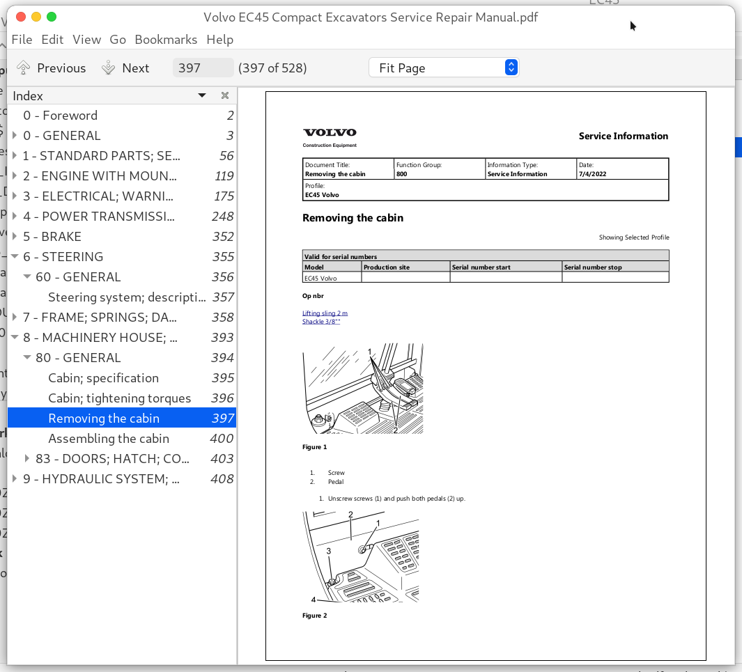
Removing the cabin.....397
Assembling the cabin.....400
83 - DOORS; HATCH; COVER PLATE; (all).....403
Cabin door; description.....404
Windscreen.....406
9 - HYDRAULIC SYSTEM; DIGGING_HANDLING_GRADING EQUIPMENT; MISCELLANEOUS.....408
90 - GENERAL.....409
Hydraulic circuit; dipper arm - Image.....410
Hydraulic circuit; dozer blade - Image.....411
Servo hydraulics - Image.....412
Hydraulic system; auxiliary pressure block - Image.....413
Hydraulic circuit; slewing gear_offset - Image.....414
Hydraulic diagram EC 45; complete - Image.....415
Hydraulic system; function diagram - Image.....416
Hydraulic components; cleanliness during handling.....417
Hydraulic system; function diagram.....418
Hydraulic diagram EC 045; complete.....420
Hydraulic circuit; slewing gear_offset.....422
Hydraulic circuit; travel system.....424
Hydraulic circuit; boom.....427
Hydraulic system; auxiliary pressure block.....429
Servo hydraulics.....431
Hydraulic circuit for bucket.....433
Hydraulic circuit; dozer blade.....435
Hydraulic circuit; dipper arm.....437
Hydraulic system; capacities.....439
Hydraulic system; description.....440
Hydraulic oil; description.....442
Hydraulic oil; storage and handling.....443
Hydraulic components; storing and transporting.....444
91 - WORKING HYDRAULIC; SERVO HYDRAULICS.....445
Solenoid valve for hydraulic working unit - Image.....447
Balancing valve (offset cylinder) Test and adjustment procedure - Image.....448
Balancing valve (offset cylinder) - Image.....449
Hydraulic oil tank; filling capacity.....450
Checking the hydraulic oil level.....451
Changing the hydraulic oil.....452
Oil cooling system.....455
Removing the oil cooler.....456
Changing the hydraulic oil filter.....459
Test and adjustment values EC 045.....461
Way valve; control valve.....463
Control valve.....465
Removing the valve block.....467
Installing the valve block.....468
Dismantling the valve block.....470
Assembling the valve block.....471
Pressure relief valves.....473
Checking and adjusting the pilot pressure.....474
Stand-by pressure.....477
Checking and adjusting the FR pressure control valve.....478
Checking and adjusting the LS pressure relief valve.....480
Tests and adjustments of the power control.....483
Checking and adjusting the dipper arm cylinder (volumetric capacity).....486
Checking and adjusting the breaker (volumetric capacity).....488
Hydraulic lock; hose rupture valve.....490
Hose rupture valve on boom cylinder-056.....492
Hose rupture valve on boom cylinder Test and adjustment procedure.....494
Hose rupture valve on boom cylinder; leak test.....496
Hose rupture valve on dipper.....497
Hose rupture valve on dipper arm cylinder; leakage test.....499
Balancing valve (offset cylinder).....500
Balancing valve (offset cylinder) Test and adjustment procedure.....502
Valve block for slewing gear.....504
Control valve block for slewing gear; test and adjustment.....507
Solenoid valve for hydraulic working unit.....509
Removing the hydraulic oil pump.....512
Installing the hydraulic pump.....514
General.....516
Auxiliary pressure block.....518
Pressure regulator (hydraulic control elements).....521
Hydraulic safety solenoid valve.....523
99 - MISCELLANEOUS.....525
Hose rupture valve on boom cylinder - Image.....526
Hose rupture valve on boom cylinder.....527
Volvo EC45 Compact Excavators Service Repair Manual
![]()