
John Deere Gator Utility Vehicle TS, TH 6X4, and TH 6X4 Diesel Diagnosis and Repair Service Manual (TM2239)
John Deere Gator Utility Vehicle TS, TH 6X4, and TH 6X4 Diesel Diagnosis and Repair Service Manual (TM2239)
tm2239 - Gator Utility Vehicle TS, TH 6X4,and TH 6X4 Diesel Technical Manual.pdf
Complete All Inclusive Technical Manual with electrical wiring diagrams for John Deere Gator Utility Vehicle TS, TH 6X4, and TH 6X4 Diesel, with all the shop information to maintain, diagnose, repair, rebuild like professional mechanics (Diagnosis, Operation, Tests, Repair, Service, Troubleshooting).
John Deere Gator Utility Vehicle TS, TH 6X4, and TH 6X4 Diesel workshop technical service manual includes:
* Numbered table of contents easy to use so that you can find the information you need fast.
* Detailed sub-steps expand on repair procedure information
* Numbered instructions guide you through every repair procedure step by step.
* Troubleshooting and electrical service procedures are combined with detailed wiring diagrams for ease of use.
* Notes, cautions and warnings throughout each chapter pinpoint critical information.
* Bold figure number help you quickly match illustrations with instructions.
* Detailed illustrations, drawings and photos guide you through every procedure.
* Enlarged inset helps you identify and examine parts in detail.
Total Pages: 1,847 pages
File Format: PDF (bookmarked, ToC, Searchable, Printable, high quality)
Language: English
tm2239 - Gator™ Utility Vehicle TS, TH 6X4,and TH 6X4 Diesel
Table of Contents
Foreword
Section 10: Safety
Group 05: Safety
Recognize Safety Information
Understand Signal Words
Replace Safety Signs
Handle Fluids Safely—Avoid Fires
Prepare for Emergencies
Prevent Battery Explosions
Prevent Acid Burns
Wear Protective Clothing
Avoid High-Pressure Fluids
Avoid Heating Near Pressurized Fluid Lines
Service Machines Safely
Use Proper Tools
Park Machine Safely
Support Machine Properly
Use Proper Lifting Equipment
Work in Clean Area
Protect Against High Pressure Spray
Illuminate Work Area Safely
Work In Ventilated Area
Remove Paint Before Welding or Heating
Avoid Harmful Asbestos Dust
Follow Tire Recommendations
Stay Clear of Rotating Drivelines
Service Cooling System Safely
Dispose of Waste Properly
Handle Chemical Products Safely
Live With Safety
Section 20: Specifications
Group 05: Fastener Torques
Metric Bolt and Screw Torque Values
Unified Inch Bolt and Screw Torque Values
Group 15: O-Ring Seal Service Recommendations
Face Seal Fittings With Inch Stud Ends Torque
Face Seal Fittings With Metric Stud Ends Torque
Service Recommendations For Flat Face O-Ring Seal Fittings
Service Recommendations for O-Ring Boss Fittings
Straight Fitting or Special Nut Torques
Metric Cap Screw Torque Values—Grade 7
Gasket Sealant Application
Group 20: General Information
Gasoline
Gasoline Storage
Diesel Fuel—North America
Diesel Fuel—Europe
Diesel Fuel Storage
Engine Oil
Engine Break-In Oil
4-Cycle Diesel Engine Oil—North America
Diesel Engine Oil—Europe
Transaxle Oil
Grease
Chain Lubricant
Alternative Lubricants
Synthetic Lubricants
Lubricant Storage
Mixing of Lubricants
Oil Filters
Group 25: Coolant
Diesel Engine Coolant
John Deere COOL-GARD™ II Coolant Extender
Group 30: Serial Number Locations
Product Serial Number
Engine Serial Number Location
Transaxle Serial Number Location
Section 30: Engine – Gas (FE290D, FE350D)
Group 05: Specifications
General Specifications
Specifications
Essential or Recommended Tools
Service Equipment and Tools
Other Material
Group 10: Component Location
Engine Components, FE290D, FE350D
Fuel System Components
Fuel System Components—Evaporative
Carburetor Components
Balancer Components
Starting Motor Components
Group 15: Theory of Operation
Lubrication System Operation
Hydraulic Lifter Operation
Evaporative Emissions System Operation
Carburetor Fuel and Air
Group 20: Diagnostics
Engine Troubleshooting Guide
Starting Motor Troubleshooting Guide (FE290D, FE350D)
Group 25: Tests and Adjustments
Throttle Cable and Pedal Stop Adjustment (FE290D, FE350D)
Choke Cable Adjustment (FE290D, FE350D)
Air Intake System Check
Governor Adjustment
Slow Idle Mixture Screw and Speed Adjustments
High Idle Speed Adjustment
Fuel Pump Pressure Test
Fuel Pump Flow Test (FE290D, FE350D)
Cylinder Compression Test (FE290D, FE350D)
Valve Clearance Adjustment (FE290D) (FE350-AS25, BS25, CS25)
Automatic Compression Release (ACR) Test
Crankcase Vacuum Test
Ignition Coil Air Gap Adjustment (FE290D, FE350D)
Oil Pressure Test
Group 30: Repair
Muffler Removal and Installation
Fuel Pump Removal and Installation
Carburetor Removal and Installation
Disassemble and Assemble Carburetor
Oil Filter and Adaptor
Engine Removal and Installation (FE290D, FE350D)
Inspect Crankcase Breather
Remove and Install Blower Housing
Remove and Install Flywheel
Remove and Install Rocker Arm (FE290D)
Remove and Install Rocker Arm (FE350D)
Inspect Rocker Arm
Remove and Install Cylinder Head
Disassemble and Assemble Cylinder Head
Inspect and Replace Cylinder Head
Recondition Valve Seats
Lap Valves
Remove and Install Crankcase Cover
Remove and Install Camshaft
Inspect Camshaft
Adjust Camshaft Axial Play (FE350D)
Inspect Automatic Compression Release (ACR)
Inspect and Replace Tappets (FE290D)
Replace Hydraulic Lifter (FE350D)
Remove Piston and Connecting Rod
Install Piston and Connecting Rod
Disassemble Piston and Connecting Rod
Assemble Piston and Connecting Rod
Inspect Piston and Connecting Rod
Reciprocating Balancer
Remove and Install Crankshaft
Analyze Crankshaft and Connecting Rod
Inspect Crankshaft
Crankshaft End Play Check
Adjust Crankshaft End Play
Replace Crankshaft Oil Seal
Inspect Cylinder Block
Measure Cylinder Bore
Deglaze Cylinder Bore
Rebore Cylinder
Disassemble and Assemble Oil Pump
Inspect Oil Pump
Inspect and Replace Governor
Inspect and Replace Governor Shaft
Replace Governor Shaft Oil Seal
Remove and Install Ignition Coil
Replace Ignition Module
Remove and Install Stator
Section 30A: Engine – Gas (FJ400D)
Group 05: Specifications
General Specifications
Test and Adjustment Specifications
Repair Specifications
Torque Specifications
Essential Tools
Other Materials
Group 10: Component Location
Summary of References
Engine Components (FJ400D)
Fuel System, Evaporative Emission Components (FJ400D)
Carburetor Components (FJ400D)
Starting Motor Components (FJ400D)
Group 15: Theory of Operation
Carburetor Fuel-Air
Governor Operation
Evaporative Emission Operation
Ignition Theory
Group 20: Diagnostics
Summary of References
System: Engine Troubleshooting Guide
System: Starting Motor Troubleshooting Guide
Group 25: Tests and Adjustments
Summary of References
Throttle Cable and Pedal Stop Adjustment (FJ400D)
Governor Static Adjustment (FJ400D)
Slow Idle Speed Adjustment (FJ400D)
Fast Idle Speed Adjustment (FJ400D)
Check Air Intake System (FJ400D)
Adjust Choke Cable (FJ400D)
Test Fuel Pump Pressure (FJ400D)
Test Fuel Pump Flow (FJ400D)
Check and Adjust Valve Clearance (FJ400D)
Test Automatic Compression Release (ACR) (FJ400D)
Adjust Ignition Coil Air Gap (FJ400D)
Test Spark (FJ400D)
Test Oil Pressure (FJ400D)
Test Crankcase Vacuum (FJ400D)
Group 30: Repair
Summary of References
Remove and Install Muffler (FJ400D)
Remove and Install Air Cleaner (FJ400D)
Remove and Install Fuel Pump (FJ400D)
Remove and Install Carburetor (FJ400D)
Disassemble and Assemble Carburetor (FJ400D)
Remove and Install Engine (FJ400D)
Inspect Crankcase Breather (FJ400D)
Remove and Install Blower Housing (FJ400D)
Remove and Install Flywheel (FJ400D)
Remove and Install Rocker Arm (FJ400D)
Remove and Inspect Push Rods (FJ400D)
Remove and Install Cylinder Head (FJ400D)
Disassemble and Assemble Cylinder Head (FJ400D)
Recondition Valve Seats (FJ400D)
Lap Valves (FJ400D)
Remove and Install Crankcase Cover (FJ400D)
Remove and Install Camshaft (FJ400D)
Inspect Camshaft (FJ400D)
Inspect Automatic Compression Release (ACR) (FJ400D)
Balancer Remove and Install (FJ400D)
Inspect and Replace Tappets (FJ400D)
Piston and Connecting Rod (FJ400D)
Remove and Install Crankshaft (FJ400D)
Inspect Crankshaft (FJ400D)
Analyze Crankshaft and Connecting Rod (FJ400D)
Crankshaft Oil Seal (FJ400D)
Inspect Cylinder Block (FJ400D)
Deglaze Cylinder (FJ400D)
Rebore Cylinder (FJ400D)
Disassemble and Assemble Oil Pump (FJ400D)
Inspect Oil Pump (FJ400D)
Remove and Install Ignition Module (FJ400D)
Remove and Install Stator (FJ400D)
Section 30B: Engine – Gas (FH601D)
Group 05: Specifications
Specifications
Essential or Recommended Tools
Service Equipment and Tools
Other Material
Group 10: Component Location
FH601D Engine
Fuel System Components
Carburetor Components
Group 15: Theory of Operation
Carbureted Engine Fuel and Air System Operation
Governor Operation
Lubrication System Operation
Group 20: Troubleshooting
Engine Troubleshooting Guide
Engine Runs Erratically/Loss Of Power
Starting Motor Troubleshooting Guide (FH601D)
Group 25: Diagnostics
Diagnostic Table
Group 30: Tests and Adjustments
Air Intake System Check
Choke Cable Adjustment (FH601D)
Throttle Cable and Pedal Stop Adjustment (FH601D)
Governor Adjustment (FH601D)
Fast Idle Speed Adjustment
Slow Idle Speed Adjustment
Fuel Pump Pressure Test
Fuel Pump Flow Test (FH601D)
Cylinder Compression Test (FH601D)
Valve Clearance Adjustment (FH601D)
Crankcase Vacuum Test (FH601D)
Oil Pressure Test (FH601D)
Ignition Coil Air Gap Adjustment
Group 35: Engine Repair
Muffler Removal and Installation (FH601D)
Fuel Pump Removal and Installation (FH601D)
Carburetor Removal and Installation (FH601D)
Carburetor Disassembly and Assembly (FH601D)
Main Jet Replacement
Intake Manifold Removal and Installation
Engine Removal and Installation (FH601D)
Blower Housing Removal and Installation (FH601D)
Cylinder Head Removal and Installation (FH601D)
Push Rod and Rocker Arm Removal and Installation
Valve Train Removal and Installation
Piston Removal and Installation
Inspect Piston and Cylinder
Cylinder Bore Honing
Cylinder Bore Resizing
Crankcase Cover Removal and Installation (FH601D)
Crankcase Cover Inspection
Governor Assembly Removal/Replacement
Governor Assembly Inspection
Camshaft/Tappet Removal and Installation
Camshaft Disassembly/Inspection
Crankshaft Removal/Replacement
Crankshaft Inspection
Connecting Rod Inspection
Breather Valve Removal and Installation
Breather Valve Inspection
Oil Pump Removal and Installation
Oil Pump Inspection (FH601D)
Oil Pickup Removal and Installation
Oil Screen Inspection/Cleaning
Flywheel Removal and Installation (FH601D)
Stator Coil Inspection
Ignition Coil Removal and Installation
Starting Motor Removal and Installation (FH601D)
Section 30C: Engine – Diesel (3TNV70, 3TNV74)
Group 05: Specifications
Specifications
Service Equipment and Tools
Other Material
Group 10: Component Location
Fuel System
Fuel Tank Components
Coolant System Components
Group 15: Theory of Operation
Cooling System Theory of Operation
Lubrication System Operation
Fuel System Theory of Operation
Air System Operation
Group 20: Diagnostics
Engine Troubleshooting and Diagnostics
Diagnose Engine Oil
Diagnose Excessive Fuel Consumption
Diagnose Incorrect Manifold Pressure
Diagnose Low Engine Compression
Diagnose Engine Starting Problem
Diagnose Poor Engine Operation
Diagnose Abnormal Coolant Temperature
Diagnose Coolant in Oil or Oil in Coolant
Diagnose Engine
Group 25: Tests and Adjustments
Summary of References
Air Restriction Indicator Test
Adjust Fast Idle Speed
Adjust Slow Idle
Throttle Cable Adjustment
Adjust Valve Clearance
Check Valve Lift
Test Cylinder Compression
Adjust Water Pump/Alternator Drive Belt
Test Thermostat
Test Radiator Bubble
Test Cooling System Pressure
Test Radiator Cap Pressure
Engine Oil Pressure Test
Test Fuel Injection System
Test Fuel Injection Nozzle
Adjust Injection Pump Timing
Check Injection Pump Static Timing
Bleed Fuel System Air
Test Fuel Transfer Pump Flow
Test Fuel Transfer Pump Pressure
Group 30: Repair
Summary of Reference
Engine Removal and Installation (Diesel—3TNV70)
Muffler Removal and Installation Diesel (3TNV70)
Exhaust Manifold Removal and Installation
Remove and Install Rocker Arm Cover
Remove and Install Rocker Arm and Push Rods
Cylinder Head Removal and Installation Diesel (3TNV70)
Recondition Cylinder Head
Remove and Install Rear Crankshaft Oil Seal
Remove and Install Front Crankshaft Oil Seal
Remove and Install Timing Gear Cover
Check Camshaft End Play
Check Timing Gear Backlash
Remove and Install Idler Gear
Remove and Install Cam Followers
Remove and Install Camshaft (3TNV70)
Remove and Install Oil Pan and Strainer
Check Connecting Rod Side Play
Check Crankshaft End Play
Check Connecting Rod Bearing Clearance
Check Crankshaft Main Bearing Clearance
Remove, Inspect, and Install Connecting Rod
Disassemble and Assemble Pistons
Cylinder Bore
Remove and Install Crankshaft and Main Bearings
Remove and Install Flywheel (3TNV70)
Remove and Install Flywheel Plate
Remove and Install Timing Gear Housing
Remove and Install Oil Pump
Coolant Temperature Switch
Remove and Install Thermostat
Remove and Install Water Pump
Fuel Filter Components
Remove and Install Fuel Transfer Pump
Remove and Install Fuel Injection Nozzle
Disassemble, Clean, Inspect, and Assemble Fuel Injector
Remove and Install Fuel Injection Pump
Remove and Install Fuel Control and Governor Linkage
Remove and Install Fuel Shutoff Solenoid
Starting Motor Removal and Installation
Repair Alternator
Section 40: Electrical
Group 05: General Information
Operation and Diagnostics
Diagnostic Information
Wire Color Abbreviation Chart
Reading Electrical Schematics
Common Circuit Tests
Conductors for 12 Volt Circuits
Group 10: Specifications
General Electrical Specification
Service Equipment and Tools
Group 15: Component Location
Main Wiring Harness—TS Gators
Main Wiring Harness—TH Gas Gators
Main Wiring Harness—TH Diesel Gators
Cooling System Electrical Component Location—TH Diesel
Group 20: Schematics and Harnesses
Electrical Schematic and Wiring Harness Legend—TS and TH Gas Gators
Electrical Schematic and Wiring Harness Legend—TH Diesel Gator
Main Wiring Schematic—TS Gators (SN -100000)
Main Wiring Schematic—TS Gators (SN 100001-)
Main Wiring Harness—TS Gators (SN -100000)
Main Wiring Harness—TS Gators (SN 100001-)
Main Wiring Harness Wire Color Codes—TS Gators
Main Wiring Schematic—TH Gas Gators (SN -006629)
W1 Main Wiring Harness—TH Gas Gators (SN -006629)
Main Wiring Schematic—TH Gas Gators (SN 006630-)
W1 Main Wiring Harness—TH Gas Gators (SN 006630-)
Main Wiring Harness Wire Color Codes—TH Gas Gators
Main Wiring Schematic—TH Diesel Gators (SN -002013)
W1 Main Wiring Harness—TH Diesel Gators (SN -002013)
Main Wiring Schematic—TH Diesel Gators (SN 002014-050000)
W1 Main Wiring Harness—TH Diesel Gators (SN 002014-050000)
Main Wiring Schematic—TH Diesel Gators (SN 050001-110000)
W1 Main Wiring Harness—TH Diesel Gators (SN 050001-110000)
Main Wiring Schematic—TH Diesel Gators (SN 110001-)
W1 Main Wiring Harness—TH Diesel Gators (SN 110001-)
Main Wiring Harness Wire Color Codes—TH Diesel Gators
W2 Engine Wiring Harness—TS Gators
W2 Engine Wiring Harness—TH Gas Gators
W2 Engine Wiring Harness—TH Diesel Gators (glow plugs)
G2 Stator—Gas Engines
Group 25: Operation and Diagnostics
Power Circuit Operation—TS and TH Gas
Power Circuit Operation—TH Diesel
Power Circuit Schematic—TS Gas (SN -100000)
Power Circuit Schematic—TS Gas (SN 100001-)
Power Circuit Schematic—TH Gas
Power Circuit Schematic—TH Diesel
Power Circuit Diagnosis—TS and TH Gas
Power Circuit Diagnosis—TH Diesel
Cranking Circuit Operation—TS
Cranking Circuit Operation—TH Gas
Cranking Circuit Operation—TH Diesel
Cranking Circuit Schematic—TS
Cranking Circuit Schematic—TH Gas
Cranking Circuit Schematic—TH Diesel
Cranking System Diagnosis—TS
Cranking Circuit Diagnosis—TH Gas
Cranking Circuit Diagnosis—TH Diesel
Ignition Circuit Operation—TS and TH Gas
Ignition Circuit Wiring Schematic—TS
Ignition Circuit Wiring Schematic—TH Gas
Ignition Circuit Diagnosis—TS and TH Gas
Charging Circuit Operation—TS and TH Gas
Charging Circuit Operation—TH Diesel
Charging Circuit Schematic—TS (SN -100000)
Charging Circuit Schematic—TS (SN 100001-)
Charging Circuit Schematic—TH Gas
Charging Circuit Schematic—TH Diesel
Charging Circuit Diagnosis—TS
Charging Circuit Diagnosis—TH Gas
Charging Circuit Diagnosis—TH Diesel
Headlight Circuit Operation—TS and TH Gas
Headlight Circuit Operation—TH Diesel
Headlight Circuit Wiring Schematic—TS and TH Gas Gators
Headlight Circuit Wiring Schematic—TH Diesel
Headlight Circuit Diagnosis—TS and TH Gas
Headlight Circuit Diagnosis—TH Diesel
Fuel Shutoff Circuit Operation—TH Gas
Fuel Shutoff Circuit Operation—TH Diesel
Fuel Shutoff Circuit Wiring Schematic—TH Gas
Fuel Shutoff Circuit Wiring Schematic—TH Diesel (Run Position)
Fuel Shutoff Circuit Wiring Schematic—TH Diesel (Start Position)
Fuel Shutoff Circuit Diagnosis—TH Gas
Fuel Shutoff Circuit Diagnosis—TH Diesel
Park Brake Light Circuit Operation—TS
Park Brake and Differential Lock Lights Circuit Operation—TH Gas
Park Brake and Differential Lock Lights Circuit Operation—TH Diesel
Park Brake Light Circuit Schematic—TS (SN -100000)
Park Brake Light Circuit Schematic—TS (SN 100001-)
Park Brake and Differential Lock Lights Circuit Schematic—TH Gas
Park Brake and Differential Lock Lights Circuit Schematic—TH Diesel
Park Brake Light Circuit Diagnosis—TS
Differential Lock and Park Brake Lights Diagnosis—TH Gas
Differential Lock and Park Brake Lights Diagnosis—TH Diesel
Hour Meter Circuit Operation—TS and TH Gas
Hour Meter Operation—TS (SN 30001-)
Hour Meter and Oil Pressure Light Circuit Operation—TH Diesel
Hour Meter Circuit Wiring Schematic—TS and TH Gas
Hour Meter and Oil Pressure Light Circuit Wiring Schematic—TH Diesel
Hour Meter Circuit Diagnosis—TS and TH Gas
Hour Meter and Oil Pressure Light Circuit Diagnosis—TH Diesel
Power Port Operation—TS and TH Gas
Power Port Operation—TH Diesel
Power Port Wiring Schematic—TS and TH Gas
Power Port Wiring Schematic—TH Diesel
Power Port Circuit Diagnosis—TS and TH Gas
Power Port Circuit Diagnosis—TH Diesel
Cooling System Circuit Operation—TH Diesel
Cooling System Circuit Electrical Schematic—TH Diesel
Cooling System Circuit Diagnosis—TH Diesel
Glow Plug Circuit Operation—TH Diesel
Glow Plug Circuit Electrical Schematic—TH Diesel
Glow Plug Circuit Diagnosis—TH Diesel
Group 30: Tests and Adjustments
Summary of References
Ground Circuit Tests
Charge Battery
Battery Load Test
Stator—Unregulated Voltage Output Test—TS
Stator—Unregulated Voltage Output Test—TH Gas
Stator—Regulated Amperage and Voltage Tests—TS and TH Gas
Regulator/Rectifier Test—TH Gas
Alternator Regulated Amperage and Voltage Test—TH Diesel
Alternator Unregulated Amperage Test—TH Diesel
Starting Motor Solenoid Test
Starting Motor Loaded Amperage Draw Test
Starting Motor No-Load Amperage and RPM Tests
Brake Lights Switch Test
Relay Test
Fuel Shutoff Solenoid Test—TH Diesel
Spark Test
Ignition Coil Air Gap Adjustment—TS and TH Gas
Spark Plug Cap Test
Spark Plug Gap Adjustment
Flywheel Magnet Test
Glow Plug Test—TH Diesel
Key Switch Test
Headlight Switch Test (2 Position)
Light Switch Test (3 Position)
Neutral Start Switch Test
Park Brake or Differential Lock Switch Test
Cooling Fan Temperature Switch Test—TH Diesel
Engine Coolant Temperature Switch Test
Turn Signal Lights Switch Test
Hazard Lights Switch Test
Raise/Lower Switch Test
Horn Switch Test, Push
Diode Test
Engine Oil Pressure Switch Test
Bulb Test
Fuse Test
Group 35: Repair
Summary of References
Alternator Disassembly, Inspection, and Assembly—TH Diesel
Starting Motor Removal and Installation—TS FE290D, FE350D Engine
Starting Motor Removal and Installation—TS FJ400D Engine
Starting Motor Removal and Installation—TH Gas
Starting Motor Solenoid Tests—All Models
Starting Motor Test—Gas Engine Models
Starting Motor Disassembly and Assembly—TS and TH Gas
Starting Motor Inspection—TS and TH Gas
Winch Remote Switch Test
Group 40: Attachments Theory of Operation
Attachments Circuit Operation
Group 45: Optional Light Kits
Rear Marker/Brake Lights Kit Operation—TS and TH Gas
Rear Marker/Brake Lights Kit Operation—TH Diesel
Rear Marker/Brake Lights Kit Schematic—TS and TH Gas
Rear Marker/Brake Lights Kit Schematic—TH Diesel
Rear Marker/Brake Lights Circuit Wiring Harness
Rear Marker/Brake Lights Kit Circuit Schematic
Rear Marker/Brake Lights Kit Circuit Wiring Harness Color Codes
Rear Lights Kit Schematic (SN 50001-)
Rear Lights Adaptor Wiring Harness (SN 50001-)
Rear Lights Adaptor Schematic (SN 50001-)
Taillights Wiring Harness (SN 50001-)
Taillights Schematic (SN 50001-)
Brake Switch Circuit Wiring Harness
Brake Switch Circuit Schematic
Brake Switch Circuit Wiring Harness Color Codes
Rear Marker/Brake Lights Kit Diagnosis TS and TH
Group 50: Optional Deluxe Light Kit
Turn Signal/Hazard/Marker/Brake Lights Operation—TS and TH Gas
Turn Signal/Hazard/Marker/Brake Lights Operation—TH Diesel
Turn Signal/Hazard/Marker/Brake Lights Kit Circuit Schematic—TS and TH Gas
Turn Signal/Hazard/Marker/Brake Lights Kit Circuit Schematic—TH Diesel
Signal Lights Wiring Harness
Front Signal Lights Wiring Harness Schematic
Front Signal Lights Wiring Color Codes
Rear Marker/Brake/Turn/Hazard Lights Circuit Wiring Harness
Rear Marker/Brake Lights Kit Circuit Schematic
Rear Marker/Brake Lights Kit Circuit Wiring Harness Color Codes
Turn Signal Lights Circuit Diagnosis
Hazard Lights Circuit Diagnosis
Rear Marker Lights Diagnosis—TS & TH
Brake Lights Diagnosis- TS and TH
Group 55: Homologated Light and Horn—Diesel
Homologated Light and Horn Wiring Harness (SN -050000)
Homologated Light and Horn Schematic (SN -050000)
Homologated Light and Horn Wiring Harness (SN 050001-)
Homologation Schematic (SN 050001-)
Light and Horn Kit Harness Wire Color Codes
Homologated Lights Circuit Diagnosis
Homologated Horn Circuit Diagnosis
Group 60: Hydraulic Front Implement Lift Kit
Hydraulic Front Implement Lift Operation—TS and TH Gas
Hydraulic Front Implement Lift Operation—TH Diesel
Hydraulic Front Implement Lift Circuit Schematic—TS and TH Gas
Hydraulic Front Implement Lift Circuit Schematic—TH Diesel
Hydraulic Front Implement Lift Wiring Harness
Hydraulic Front Implement Lift Schematic
Hydraulic Front Implement Lift Wiring Color Codes
Hydraulic Front Implement Lift Circuit Diagnosis
Group 65: Optional Gauges Kit
Gauges Kit Component Location—TS & TH Gators
Gauges Kit Operation
Gauges Kit Wiring Schematic—TS and TH Gas
Gauges Kit Wiring Schematic—TH Diesel
Gages Kit Wiring Harness
Gauges Kit Circuit Wiring Harness Color Codes
Group 70: Horn Kit
Horn Kit Component Location
Horn Kit Circuit Operation
Horn Kit Circuit Wiring Schematic—TS and TH Gas Gators
Horn Kit Circuit Wiring Schematic—TH Diesel Gators
Horn Kit Wiring Harness
Horn Kit Wiring Harness Schematic
Horn Kit Circuit Wiring Harness Color Codes
Horn Kit Circuit Diagnosis
Group 75: Backup Alarm
Backup Alarm Kit Circuit Operation—T-Series Gas (SN -050000)
Backup Alarm Kit Circuit Operation—T-Series Gas (SN 050001-)
Backup Alarm Kit Circuit Operation—TH Diesel (SN -050000)
Backup Alarm Kit Circuit Operation—TH Diesel (SN 050001-)
Backup Alarm Kit Circuit Wiring Schematic—T-Series Gas
Backup Alarm Kit Circuit Wiring Schematic—TH Diesel
Backup Alarm Kit Wiring Harness
Backup Alarm Kit Wiring Harness Schematic
Backup Alarm Kit Wiring Color Codes
T-Series Backup Alarm Kit Circuit Diagnosis
Group 80: Cargo Box Lift Kit
Cargo Box Actuator Components
Cargo Box Lift Theory of Operation
Cargo Box Lift Kit Circuit Operation—TS and TH Gas
Cargo Box Lift Kit Circuit Operation—TH Diesel
Cargo Box Lift Kit Circuit Schematic—TS and TH Gas
Cargo Box Lift Kit Circuit Schematic—TH Diesel
Cargo Box Lift Kit Wiring Harness
Cargo Box Lift Kit Wiring Harness (Detail)
Cargo Box Lift Kit Wiring Harness Schematic
LH Cargo Box Lift Kit Wire Color Codes
Cargo Box Lift System Troubleshooting
Cargo Box Lift Kit Circuit Diagnosis—TS and TH Gas Gators
Cargo Box Lift Kit Circuit Diagnosis—TH Diesel Gators
Group 85: Winch
Specifications
Winch Circuit Schematic—TS and TH Gas
Winch Circuit Schematic—TH Diesel
Winch Wiring Harnesses
Winch Wiring Harness Color Codes
Relay Block and Remote Switch
Winch Theory of Operation
Winch Circuit Diagnostics
Group 90: Heater Kit
Heater Specifications
Heater Operation
Heater Troubleshooting
Heater Schematic
Heater Wiring Harness
Heater Diagnosis
Section 50: Power Train
Group 05: Specifications
Specifications
Essential or Recommended Tools
Other Material
Group 10: Component Location
Summary of References
Transaxle Case Components
Transaxle Gear Components
TH 6X4—Axle Housing Components
TS—Axle Housing Components
Differential Components
Differential Shift Components
Drive Clutch
Driven Clutch
Group 15: Theory of Operation
Clutch Operation
Group 20: Diagnostics
Diagnostic Check Points
Group 25: Tests and Adjustments
Summary of References
Transaxle Shift Adjustment
Differential Lock Cable Adjustment
Differential Lock Switch Adjustment—TH
Drive Train Performance Tests
Driven Clutch Back-Shifting Check
Clutch Center Distance Check—Diesel Machines
Drive Chain Adjustment—TH
Group 30: Repair
Summary of References
Drive Clutch Removal and Installation—TS
Drive Clutch Removal and Installation—TH
Driven Clutch Removal and Installation
Drive Clutch Disassembly and Assembly
Driven Clutch Disassembly and Assembly
Driven Clutch Ramp Button Replacement
Transaxle Removal and Installation—TS
Transaxle Removal and Installation—TH
Transaxle Disassembly and Assembly
Axle Shaft Seal Removal and Installation
Section 60: Steering
Group 05: Specifications
Specifications
Group 10: Component Location
Steering Component Location
Group 15: Diagnostics
Troubleshooting
Steering System Checks
Group 20: Tests and Adjustments
Summary of References
Toe-In Adjustment
Steering Wheel Removal, Installation, and Adjustment
Group 25: Repair
Summary of References
Tie Rod End Removal and Installation
Steering Assembly Removal and Installation
Spindle Shaft and Bushing Removal and Installation
Steering Rack Boot Removal and Installation
Section 70: Brakes
Group 05: Specifications
Specifications
Other Material
Group 10: Component Location
Brake and Brake Cable
Transaxle Brake
Park Brake and Differential Lock Linkage
Group 15: Theory of Operation
Brake Operation
Park Brake and Differential Lock Operation
Group 20: Diagnostics
Diagnosis Test/Check Points
Troubleshooting Guide
Group 25: Tests and Adjustments
Summary of References
Brake Function Test
Brake Pedal Freeplay Adjustment
Brake Adjustment
Group 30: Repair
Summary of References
Brake Cable Removal and Installation
Brake Pedal Assembly Removal and Installation
Parking Brake Removal and Installation
Brake Rods Removal and Installation
Brake Disc Assembly Removal and Installation
Section 80: Miscellaneous
Group 05: Specifications
Specifications
Group 10: Repair
Summary of References
Hood Removal and Installation
Front Skid Plate Removal and Installation
Front Grille Removal and Installation
Seat Removal and Installation
Seat Base Cover Removal and Installation
Battery Removal and Installation—Gas Engine Models
Battery Removal and Installation—Diesel Models
Shock Absorber Removal and Installation
Control Arm Removal and Installation
Front Wheel Removal and Installation
Front Wheel Bearing Replacement
Rear Wheel Removal and Installation
Cargo Box Removal and Installation
Cargo Box Side Removal and Installation (SN 50001- )
Dash Panel Removal and Installation
Headlight Lamp Housing Removal and Installation
Fuel Tank Removal and Installation
Fuel Tank Removal and Installation TS (SN 100001-)
Carbon Canister Removal and Installation (SN 100001-)
Front Fender Removal and Installation
Rear Fender Removal and Installation—TS Gators
Rear Fender Removal and Installation—TH Gators
Servicing Cooling System
Front Radiator Removal and Installation
Side Radiator Removal and Installation
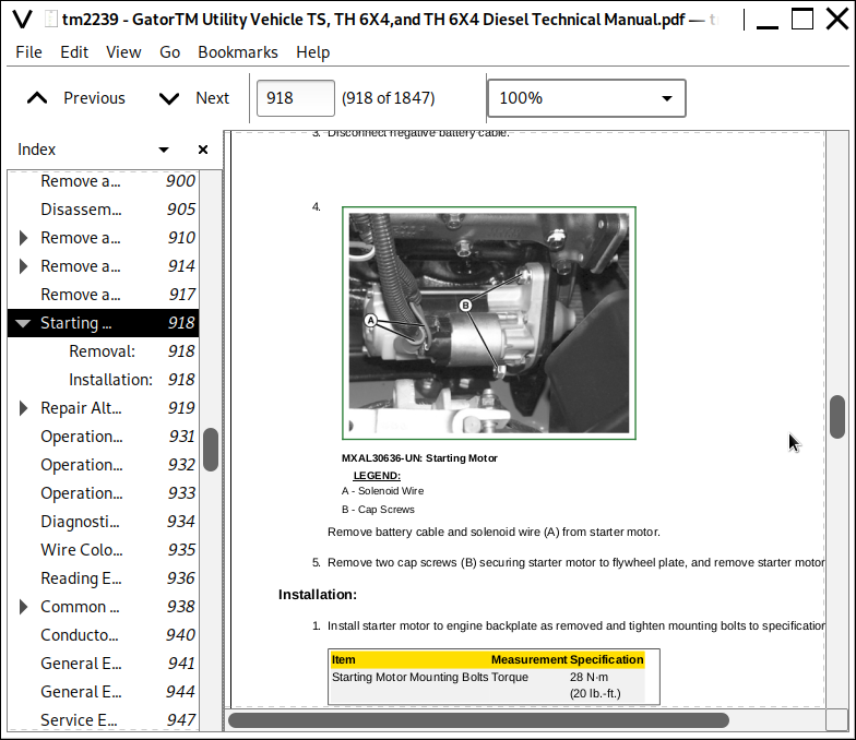
![]()