Caterpillar ASPHALT SCREED AS2252C Repair Service Manuals (SN Prefix TDS)
Complete service repair manuals with electrical wiring diagrams for Caterpillar ASPHALT SCREED AS2252C, with all the workshop service information to maintain, diagnose, repair, and rebuild.
Caterpillar Caterpillar ASPHALT SCREED AS2252C Repair Service Manuals
workshop service manual includes:
* Numbered table of contents easy to use so that you can find the information you need fast.
* Detailed sub-steps expand on repair procedure information
* Numbered instructions guide you through every repair procedure step by step.
* Troubleshooting and electrical service procedures are combined with detailed wiring diagrams for ease of use.
* Notes, cautions and warnings throughout each chapter pinpoint critical information.
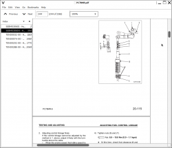
* Bold figure number help you quickly match illustrations with instructions.
* Detailed illustrations, drawings and photos guide you through every procedure.
* Enlarged inset helps you identify and examine parts in detail.
KENR5998 - Disassembly and Assembly (AS2252C Asphalt Screed).pdf
KENR6687 - Schematic (AS-2252C Screed Electrical System 253-4749).pdf
KENR6688 - Schematic (AS2251C and AS2302C Screed Hydraulic System 253-4750-02).pdf
KENR6951-02 - Specifications (AS2252C Asphalt Screed).pdf
KENR6951-02 - Systems Operation (AS2252C Asphalt Screed).pdf
KENR6951-02 - Testing and Adjusting (AS2252C Asphalt Screed).pdf
KENR8228 - Systems Operation; Troubleshooting; Testing and Adjusting (Cat® Grade and Slope v2.2x for Pavers and Cold Planers).pdf
Total Pages: 471 pages
File Format: PDF (bookmarked, ToC, Searchable, Printable, high quality)
Manual Type: Disassembly & Assembly, Testing & Adjusting, Specifications, Systems Operation, Electrical Schematic, Troubleshooting...
Language: English
AS2252C ASPHALT SCREED TDS
TABLE OF CONTENTS
KENR5998 - Disassembly and Assembly (AS2252C Asphalt Screed)................1
Screed - Remove and Install................3
Platform - Remove and Install................10
Screed Plate (Main) - Remove and Install................20
Screed Plate (Extender) - Remove and Install................31
Heating Element (Main Screed) - Remove and Install................39
Heating Element (Extender) - Remove and Install................41
Flow Divider Valve - Remove and Install................45
Gear Motor (Vibratory - Main) - Remove................48
Gear Motor (Vibratory - Extender) - Remove................51
Gear Motor (Vibratory) - Disassemble................55
Gear Motor (Vibratory) - Assemble................59
Gear Motor (Vibratory - Main) - Install................64
Gear Motor (Vibratory - Extender) - Install................66
Vibratory Group (Main) - Remove................70
Vibratory Group (Extender) - Remove................73
Vibratory Group - Disassemble................78
Vibratory Group - Assemble................80
Vibratory Group (Main) - Install................82
Vibratory Group (Extender) - Install................84
Power Adjuster Motor Group (Crown) - Remove................88
Power Adjuster Motor Group (Crown) - Disassemble................89
Power Adjuster Motor Group (Crown) - Assemble................91
Power Adjuster Motor Group (Crown) - Install................93
Power Adjuster Motor Group (Extender Height) - Remove................94
Power Adjuster Motor Group (Extender Height) - Disassemble................96
Power Adjuster Motor Group (Extender Height) - Assemble................98
Power Adjuster Motor Group (Extender Height) - Install................100
Height Adjuster Jack (Extender) - Remove and Install................102
Height Adjuster Group (Extender) - Remove................105
Height Adjuster Group (Extender) - Disassemble................108
Height Adjuster Group (Extender) - Assemble................110
Height Adjuster Group (Extender) - Install................112
Manual Adjuster (Screed Plate Angle) - Remove and Install................115
Solenoid Valve (Extender Extend and Extender Slope) - Remove................118
Solenoid Valve (Extender Extend and Extender Slope) - Disassemble................121
Solenoid Valve (Extender Extend and Extender Slope) - Assemble................124
Solenoid Valve (Extender Extend and Extender Slope) - Install................127
Hydraulic Cylinder (Extender Extend) - Remove and Install................129
Hydraulic Cylinder (Extender Slope) - Remove and Install................132
Screed Chain (Crown) - Remove and Install................135
Drive Shaft (Crown) - Remove................138
Drive Shaft (Crown) - Disassemble................140
Drive Shaft (Crown) - Assemble................141
Drive Shaft (Crown) - Install................142
Thickness Control - Remove................144
Thickness Control - Disassemble................145
Thickness Control - Assemble................146
Thickness Control - Install................147
Drop Arm - Remove and Install................148
Extender Carriage - Remove................152
Extender Carriage - Disassemble................156
Extender Carriage - Assemble................158
Extender Carriage - Install................160
Shoe (End Gate) - Remove and Install................163
Actuator (End Gate) - Remove and Install................165
End Gate - Remove and Install................167
Screed Frame (Extender) - Remove and Install................169
KENR6687 - Schematic (AS-2252C Screed Electrical System 253-4749)................180
Collage................181
Main................196
KENR6688 - Schematic (AS2251C and AS2302C Screed Hydraulic System 253-4750-02)................198
Collage................199
Main................207
Features................207
Cover Page................208
Information................0
Component Location................209
Fluid Power Symbols................210
Electrical Symbols................211
Schematic................212
Machine View................0
Machine Component Locations................213
KENR6951-02 - Specifications (AS2252C Asphalt Screed)................214
Drop Arm................215
Screed Plate - 457.2 mm (18 inch) Berm Extender................216
Screed Plate................218
Screed Plate - Without Berm Extender................220
Screed Plate - 304 mm (12 inch) Berm Extender................222
Crown Group................224
Power Adjuster Motor (Crown)................225
Power Adjuster Motor (Height)................227
Flow Divider Valve................228
Gear Motor (Vibratory)................229
Vibratory Lines Group................230
Vibratory Group................232
Height Adjuster Group................234
Height Adjuster - Clockwise................237
Height Adjuster - Counter Clockwise................238
Slope Lines Group................239
Solenoid Valve (Extender Extend and Extender Slope)................241
Extension Lines Group................242
Hydraulic Cylinder (Extender)................244
Berm Lines Group................245
Solenoid Valve (Berm)................246
Hydraulic Cylinder (Berm)................247
End Gate................248
Screed Wiring................249
Screed Frame................250
Extender Carriage................252
Wiring (Screed Heater)................254
Operator Platform................256
KENR6951-02 - Systems Operation (AS2252C Asphalt Screed)................257
Graphic Color Codes................258
Screed Hydraulic System................260
Operator Controls................269
Screed Components................276
Screed Control System................289
Electric Heat System................298
Electrical Schematic................315
KENR6951-02 - Testing and Adjusting (AS2252C Asphalt Screed)................317
Machine Preparation for Troubleshooting................318
Visual Inspection................320
Screed Troubleshooting................323
Screed Plate - Check and Adjust................330
Height Adjuster - Check and Adjust................331
Berm - Check and Adjust................334
Heater Element - Test................336
Temperature Sensor (Electric Heat) - Test................342
KENR8228 - Systems Operation; Troubleshooting; Testing and Adjusting (Cat® Grade and Slope v2.2x for Pavers and Cold Planers)................346
System Components................347
Modes of Operation................356
Display Icons................361
Menus................375
Configuration Menu................376
Installation Menu................393
System Setup................399
Display................401
Data Link................411
General Information................415
Service Tools................422
Diagnostic Capabilities................424
Valve Speed - Set................434
Valve - Calibrate................442
Sensor - Calibrate................450
Electrical Connector - Inspect................452
Wiring Harness (Open Circuit) - Test................461
Wiring Harness (Short Circuit) - Test................462
Module - Flash Program................463
Module - Replace................465
System Schematic................468
Caterpillar ASPHALT SCREED AS2252C Repair Service Manuals (SN Prefix TDS)


