
Volvo L90B Wheel Loaders Service Repair Manual
Volvo L90B Wheel Loaders Service Repair Manual
Complete official service repair manual with Electrical Wiring Diagrams for Volvo L90B Wheel Loaders, with all the workshop information to maintain, test, repair, service like professional mechanics.
Volvo L90B Wheel Loaders workshop service repair manual includes:
* Numbered table of contents easy to use so that you can find the information you need fast.
* Detailed sub-steps expand on repair procedure information
* Numbered instructions guide you through every repair procedure step by step.
* Troubleshooting and electrical service procedures are combined with detailed wiring diagrams for ease of use.
* Notes, cautions and warnings throughout each chapter pinpoint critical information.
* Bold figure number help you quickly match illustrations with instructions.
* Detailed illustrations, drawings and photos guide you through every procedure.
* Enlarged inset helps you identify and examine parts in detail.
PRODUCT DETAILS:
Total Pages: 703 pages
File Format: PDF (bookmarked, Searchable, Printable, high quality)
Language: English
0 - GENERAL
1 - STANDARD PARTS, SERVICE
2 - ENGINE WITH MOUNTING AND EQUIPMENT
3 - ELEC. SYSTEM; WARNING SYSTEM; INFORMATION SYSTEM; INSTRUMENTS
4 - POWER TRANSMISSION
5 - BRAKE
6 - STEERING
7 - FRAME; SPRINGS; DAMPING; AXLE SUSPENSION; WHEEL_TRACK UNIT
8 - MACHINERY HOUSE; CAB; EXTERIOR TRIM PARTS ANYWHERE
9 - HYDRAULIC SYSTEM; DIGGING_HANDLING_GRADING EQUIPM.; MISC EQUIPM
Foreword
0 - GENERAL
00 - DESCRIPTION; COMPLETE MACHINE
Description-[0521]
Product Identification Plates
03 - SPECIFICATIONS
Brakes, L120B
Brakes, L90B
Capacities
Electrical system, L120B
Electrical system, L90B
Engine, L120B
Engine, L90B
Hydraulic system, L120B
Hydraulic system, L90B
Power transmission, L120B
Power transmission, L90B
Servo system, L120B
Servo system, L90B
Steering system, L120B
Steering system, L90B
Tightening torques
VOLVO BM standard tightening torques
Weights, (approx.)
07 - STANDARD TIME
Time Guide
08 - TOOL
E-Tools
1 - STANDARD PARTS, SERVICE
17 - SERVICE
Charging of batteries-[0042]
Cleanliness brake and hydraulic systems
Electric welding
Repairing hydraulic systems
Towing the machine
19 - GENERAL
A few simple rules for batteries
A few simple rules of safety
A few simple rules when inflating tyres
A few simple rules when servicing
Charging batteries
Danger in connection with polymer materials
Measures to prevent a fire
Refrigerant in air-conditioning units
Safety concerns everybody!
Service position
Starting with booster batteries
2 - ENGINE WITH MOUNTING AND EQUIPMENT
20 - GENERAL
21 - ENGINE
Checking function, engine
Engine, fitting
Engine, removing
Specifications-[5529]
Specifications-[5543]
Specifications, L120B-[5557]
Specifications, L90B-[5609]
22 - LUBRICATING SYSTEM
Specifications, L120B-[5446]
Specifications, L90B-[5458]
23 - FUEL SYSTEM
Checking rotational speed with frequency meter
Fuel system, bleeding
Idling speed, checking and adjusting
Injection timing, checking and adjusting
Specifications, L120B-[5158]
Specifications, L120B-[5231]
Specifications, L120B-[5257]
Specifications, L120B-[5322]
Specifications, L90B-[5217]
Specifications, L90B-[5243]
Specifications, L90B-[5309]
Specifications, L90B-[5334]
25 - INLET & EXHAUST SYSTEM
Specifications-[5100]
Specifications-[5114]
Specifications, L120B-[5128]
Specifications, L90B-[5140]
26 - COOLING SYSTEM
Radiator, changing
Specifications-[4950]
Specifications-[5004]
Specifications, L120B-[5032]
Specifications, L90B-[5044]
3 - ELECTRICAL; WARNING; INFORMATION; INSTRUMENTS
30 - GENERAL
Description
Special instructions when working on the electrical systems
Specifications-[4912]
31 - BATTERY
Charging of batteries
Specifications-[4843]
32 - ALTERNATOR; CHARGE REGULATOR
Specifications-[4826]
33 - STARTING SYSTEM
Preheating, description of function
Specifications-[4810]
Starting engine, description of function
Stop solenoid, description of function
35 - LIGHTING
Headlights, adjusting
Specifications-[4724]
36 - OTHER ELECTRICAL EQUIPMENT
Code key for connectors (connected to the circuit board)
Code key for connectors (others)
Code key for diodes
Control unit function, general description
Emergency operational, electrical
Functions which are not included in the central warning
Monitored functions
Other electrical functions (controlled by the control unit)
Units connected to the control unit
37 - CABLE; FUSE; RELAY
Circuit board
Codes used in wiring diagrams
Component location, circuit 101–108
Component location, circuit 11–110
Component location, circuit 111–117
Component location, circuit 121–129
Component location, circuit 131–1310
Component location, circuit 141–147
Component location, circuit 151–155
Component location, circuit 161–168
Component location, circuit 171–177
Component location, circuit 181–187
Component location, circuit 191–197
Component location, circuit 201–2010
Component location, circuit 211–2110
Component location, circuit 21–210
Component location, circuit 221–229
Component location, circuit 31–310
Component location, circuit 41–410
Component location, circuit 51–510
Component location, circuit 61–610
Component location, circuit 71–79
Component location, circuit 81–810
Component location, circuit 91–97
Electrical distribution box
Explanations to wiring diagrams
Fuses
List of circuits
Relays
Specifications-[3259]
Wiring diagram, circuit 101–108
Wiring diagram, circuit 11–110
Wiring diagram, circuit 111–117
Wiring diagram, circuit 121–129
Wiring diagram, circuit 131–1310
Wiring diagram, circuit 141–147
Wiring diagram, circuit 151–155
Wiring diagram, circuit 161–168
Wiring diagram, circuit 171–177
Wiring diagram, circuit 181–187
Wiring diagram, circuit 191–197
Wiring diagram, circuit 201–2010
Wiring diagram, circuit 211–2110
Wiring diagram, circuit 21–210
Wiring diagram, circuit 221–229
Wiring diagram, circuit 31–310
Wiring diagram, circuit 41–410
Wiring diagram, circuit 51–510
Wiring diagram, circuit 61–610
Wiring diagram, circuit 71–79
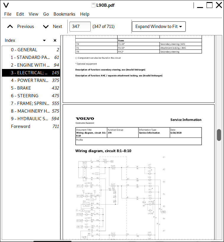
Wiring diagram, circuit 81–810
Wiring diagram, circuit 91–97
38 - INSTRUMENT; SENSOR; WARNING & INFORMATION SYSTEM
Centre instrument panel (control lamp panel)
Contronic System
Front left panel
Front right panel
Instruments and controls
Other controls
Right instrument panel
Service Contronic Display Unit
4 - POWER TRANSMISSION
40 - GENERAL
APS (Automatic Power Shift)
Specifications, L120B-[2933]
Specifications, L90B-[2946]
41 - CLUTCH; TORQUE CONVERTER
Specifications, L120B-[2906]
Specifications, L90B-[2917]
42 - TRANSMISSION; HYDRAULIC CONTROL
Gear selector valve
Gear selector valve _ transmission
Oil Pressures, checking (all)
Specifications-[0058]
Specifications, L120B
Specifications, L90B
Specifications
Transmission, fault tracing
Transmission, fitting (together with engine)
Transmission, removing (together with engine)
43 - GEARBOX
Specifications-[0037]
45 - PROPELLER SHAFT
Specifications-[0009]
46 - FRONT AXLE; REAR AXLE
Differential housing, changing wear ring
Differential lock, front, adjusting
Specifications-[4405]
Specifications-[4545]
Specifications, L120B-[4440]
Specifications, L120B-[4513]
Specifications, L90B-[4455]
Specifications, L90B-[4528]
5 - BRAKE
51 - WHEEL BRAKE
Description
Function
Specifications, L120B
Specifications, L90B
Specifications
52 - HYDRAULIC BRAKE SYSTEM
Accumulator, checking (Removed)
Adjusting brake pedal angle
Brake system, checking and adjusting of pressure in circuit
Brake system, checking and adjusting unloading pressure
Brake system, checking function
Brake valve
Hydraulic diagram, L120B
Hydraulic diagram, L90B
Specifications, L120B-[0615]
Specifications, L120B
Specifications, L90B-[0626]
Specifications, L90B
55 - PARKING BRAKE
Basic setting, checking and adjusting
Description
Hydraulically controlled
Specifications
6 - STEERING
60 - GENERAL
Description, L120B
Description, L90B
64 - STEERING
Description-[3651]
Function
Hydraulic diagram, basic machine (L90B)
Hydraulic diagram, basic machine, lever steering (CDC) (L120B)
Hydraulic diagram, basic machine, lever steering (CDC) (L90B)
Hydraulic diagram, basic machine , lever steering (CDC), secondary steering (L120B)
Hydraulic diagram, basic machine , lever steering (CDC), secondary steering (L90B)
Hydraulic diagram, basic machine, secondary steering (L120B)
Hydraulic diagram, basic machine, secondary steering (L90B)
Pressure _ flow compensator, description, L120B
Pressure _ flow compensator, description, L90B
Pump, description, L120B
Pump, description, L90B
Shift valve, L120B
Specifications, L120B-[3840]
Specifications, L120B-[4247]
Specifications, L90B-[3855]
Specifications, L90B-[4302]
Stand-by pressure, checking and adjusting
Steering cylinder, component location
Steering valve, description, L120B
Steering valve, description, L90B
Steering valve, L120B
Working pressure checking and adjusting
66 - LEVEL STEERING
Adjusting steering speed, lever steering
Checking the output voltage from steering lever
Control valve, lever steering (CDC)
Description of hydraulic system
Description
Hydraulic diagram, basic machine, lever steering (CDC)
7 - FRAME; SPRINGS; DAMPING; AXLE SUSPENSION; WHEEL_TRACK UNIT
71 - FRAME
General description
Specifications-[3319]
Specifications-[3337]
Specifications, L120B
Specifications, L90B
74 - FRAME LINK
Specifications
75 - AXLE SUSPENSION
Adjusting the rear rear-axle bridge axial clearance, L120B
Adjusting the rear rear-axle bridge axial clearance, L90B
Front rear-axle bridge, complete, L120B
Front rear-axle bridge, complete, L90B
Rear axle suspension, L120B
Rear axle suspension, L90B
Rear axle suspension
77 - WHEELS; TRACKS; TYRE; HUB; DRUM
Specifications-[2139]
8 - MACHINERY HOUSE; CAB; EXTERIOR TRIM PARTS ANYWHERE
81 - CAB, NAKED; CANOPY
Specifications-[2120]
87 - AIR CONDITIONING UNIT
AC safety, description of function
Description-[2104]
Description
Electrical system, description of function
Refrigerant for all air conditioning
Specifications-[1953]
9 - HYDRAULIC SYSTEM; DIGGING_HANDLING_GRADING EQUIPMENT; MISCELLANEOUS
91 - WORKING HYDRAULIC; SERVO HYDRAULICS
Adjusting automatic lifting and tilting
AHC automatic connection of attachments with hydraulic functions
AHC _ Separate attachment locking
Automatic lifting and tilting and floating position
Back-up valve, checking opening pressure-[1658]
Back-up valve, checking opening pressure
Changing or repairing hydraulic pumps-[1525]
Changing or repairing hydraulic pumps
Control valve, functions
Detent function floating position and floating position
Detent function lifting _ automatic lifting (boom kick-out)
Hydraulic diagram, detent function floating position and floating position
Hydraulic diagrams, L120B
Hydraulic diagrams, L90B
Hydraulic oil pump, checking and adjusting unloading pressure (Applies only to L120B)
Hydraulic oil pump, checking and adjusting working pressure
Sequence valves, checking and adjusting opening pressure
Servo pressure, checking and adjusting (AHC)
Servo pressure, checking and adjusting (not AHC)
Servo pressure, checking by spool in control valve
Servo valve, adjusting controls
Servo valve, function
Shock and anti-cavitation functions
Shock valve, tilting function, checking and adjusting
Specifications-[1709]
Specifications-[1718]
Specifications, L120B-[1429]
Specifications, L120B-[1536]
Specifications, L120B-[1740]
Specifications, L90B-[1441]
Specifications, L90B-[1547]
Specifications, L90B-[1754]
Specifications
Working hydraulics, description
94 - UNIT, LOAD HANDLING
Lifting cylinder, L120B
Lifting cylinder, L90B
Specifications, L120B
Specifications, L90B
Tilting cylinder, L90B _ L120B
99 - MISCELLANEOUS
Accumulator, filling with gas
Boom Suspension System, electrical system
Boom Suspension System, hydraulic system
Boom Suspension System
Checking function, boom suspension system
Valve block, boom suspension system
![]()