
John Deere 2025R and 2025R Compact Utility Tractors Diagnostic and Repair Service Manual (TM147619)
Complete All Inclusive Technical Manual with electrical wiring diagrams for John Deere 2025R and 2026R Compact Utility Tractors, with all the shop information to maintain, diagnostic, repair, service like professional mechanics (Diagnosis, Operation, Tests, Repair, Service, Troubleshooting).
John Deere 2025R and 2026R Compact Utility Tractors workshop technical service manual includes:
* Numbered table of contents easy to use so that you can find the information you need fast.
* Detailed sub-steps expand on repair procedure information
* Numbered instructions guide you through every repair procedure step by step.
* Troubleshooting and electrical service procedures are combined with detailed wiring diagrams for ease of use.
* Notes, cautions and warnings throughout each chapter pinpoint critical information.
* Bold figure number help you quickly match illustrations with instructions.
* Detailed illustrations, drawings and photos guide you through every procedure.
* Enlarged inset helps you identify and examine parts in detail.
tm147619 - 2025R and 2026R Compact Utility Tractors Diagnostic and Repair Technical Manual.pdf
tm147619 - 2025R and 2026R Compact Utility Tractors Diagnostic and Repair Technical Manual.epub
Total Pages: 1,422 pages
File Format: PDF/EPUB/MOBI/AZW (PC/Mac/Android/Kindle/iPhone/iPad; bookmarked, ToC, Searchable, Printable)
Language: English
tm147619 - 2025R and 2026R Compact Utility Tractors Diagnostic and Repair Manual
Table of Contents
Foreword
Section 10: General Information
Group 05A: Safety
Work In Ventilated Area
Recognize Safety Information
Avoid Backover Accidents
Prevent Machine Runaway
Avoid Contact with Agricultural Chemicals
Clean Vehicle of Hazardous Pesticides
Use a Safety Chain
Work in Clean Area
Decommissioning — Proper Recycling and Disposal of Fluids and Components
Avoid Harmful Asbestos Dust
Avoid Hot Exhaust
Clean Exhaust Filter Safely
Handle Fuel Safely—Avoid Fires
Prepare for Emergencies
Handle Fluids Safely—Avoid Fires
Avoid High-Pressure Fluids
Install All Guards
Use Proper Lifting Equipment
Illuminate Work Area Safely
Live With Safety
Service Machines Safely
Support Machine Properly
Remove Paint Before Welding or Heating
Park Machine Safely
Stay Clear of Rotating Drivelines
Follow Safety Instructions
Use Proper Tools
Service Tires Safely
Keep ROPS Installed Properly
Construct Dealer-Made Tools Safely
Practice Safe Maintenance
Understand Signal Words
Replace Safety Signs
Avoid Heating Near Pressurized Fluid Lines
Wear Protective Clothing
Service Accumulator Systems Safely
Handling Batteries Safely
Handle Agricultural Chemicals Safely
Service Cooling System Safely
Use Steps and Handholds Correctly
Transport Tractor Safely
Group 05B: General References
Deliver Safely
Information Available in Sections, Groups and Subgroups
Glossary of Terms
Trademarks
Group 05C: Technical Specific References
Unified Inch Bolt and Screw Torque Values
Metric Bolt and Screw Torque Values
Metric Cap Screw Torque Values—Grade 7
Gasket Sealant Application
Service Recommendations for O-Ring Boss Fittings
Service Recommendations for Flat Face O-Ring Seal Fittings
Group 05D: Fuel and Lubricants
Diesel Fuel
Handling and Storing Diesel Fuel
Engine Oil
Alternative and Synthetic Lubricants
Lubricant Storage
Mixing of Lubricants
Grease
Transmission and Hydraulic Oil
Diesel Engine Coolant
Group 05E: Serial Number Locations
Serial Numbers
Machine Product Identification Number
Engine Serial Number
Transmission Serial Number
Section 20: Engine Repair
Group 05: Engine
Engine Removal and Installation
Valve Cover Removal and Installation
Rocker Arm and Push Rod Removal and Installation
Rocker Arm and Push Rod Disassemble and Assemble
Exhaust Manifold Removal and Installation
Cylinder Head Removal and Installation
Cylinder Head Disassemble and Assemble
Cylinder Head Reconditioning
Crankshaft Rear Oil Seal Removal and Installation
Remove and Install Crankshaft Rear Oil Seal Case Removal and Installation
Replace Crankshaft Front Oil Seal Removal and Installation
Timing Gear Cover Removal and Installation
Idler Gear Removal and Installation
Camshaft Followers Removal and Installation
Camshaft Removal and Installation
Camshaft, Gear, Bushing and Bore Inspection
Oil Pan and Strainer Removal and Installation
Connecting Rod Side Play Check
Crankshaft End Play Check
Connecting Rod Bearing Clearance Check
Crankshaft Main Bearing Clearance Check
Piston and Connecting Rod Removal
Piston and Connecting Rod Installation
Piston and Connecting Rod Disassemble
Piston and Connecting Rod Assemble
Cylinder Bore Inspection
Cylinder Boring
Crankshaft and Main Bearings Removal
Crankshaft and Main Bearings Installation
Flywheel Removal and Installation
Engine Back Plate Removal and Installation
Oil Pump Inspection
Group 10: Cooling System
Fan and Alternator Belt Removal and Installation
Radiator Removal and Installation
Water Pump Removal and Installation
Thermostat Removal and Installation
Coolant Temperature Sensor Removal and Installation
Block Heater Installation
Section 30: Fuel, Air Intake, and Exhaust Repair
Group 05: Fuel
Throttle Cable Removal and Installation
Fuel Transfer Pump Removal and Installation
Fuel Injection Nozzle Removal and Installation
Fuel Injection Nozzle Clean and Inspect
Fuel Injection Pump Removal
Fuel Injection Pump Installation
Fuel Shutoff Solenoid Removal and Installation
Fuel Filter Assembly Removal and Installation
Fuel Tank Removal and Installation
Group 10: Air Intake
Air Cleaner Assembly Removal and Installation
Intake Manifold
Group 20: Exhaust
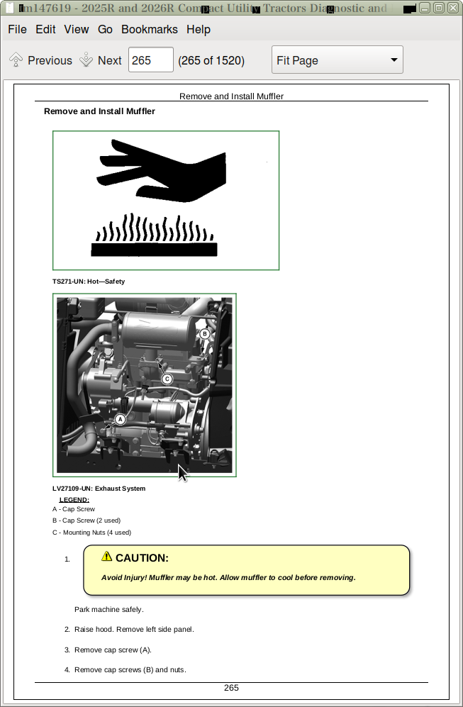
Remove and Install Muffler
Exhaust Manifold
Section 40: Electrical Repair
Group 05: Connectors
Installation of Repair Wire Assembly (RWA)
Using High-Pressure Washers
Remove Connector Body from Blade Terminals
Replace WEATHER PACK™ Connector
Install WEATHER PACK™ Contact
Repair (Pull Type) METRI-PACK™ Connectors
Repair (Push Type) METRI-PACK™ Connectors
Exploded View—CINCH Flexbox Connectors
CINCH™ Flexbox Connectors
Repair DEUTSCH™ Connectors
Group 10: Battery, Starter and Alternator
Prevent Battery Explosions
Battery Removal and Installation
Starting Motor Removal and Installation
Starting Motor Disassembly and Assembly
Starting Motor Inspection/Test
Alternator Removal and Installation
Group 15: Electrical System Components
Instrument Control Cluster (ICC) Removal and Installation
Section 50: Drive Systems and Transmission Repair
Group 10: Power Train
Transmission Removal and Installation
Hydrostatic Drive Removal and Installation
Hydrostatic Drive Disassemble
Hydrostatic Drive Assemble
Range Transmission Removal and Installation
Hydrostatic Pedals and Linkage Removal and Installation
Hydrostatic Pedals Linkage Adjustment
Group 15: MFWD
MFWD Axle Removal and Installation
MFWD Axle Disassemble
MFWD Axle Assemble
MFWD Spindle Shaft Disassemble
MFWD Spindle Shaft Assemble
MFWD Differential Disassemble
MFWD Differential Assemble
MFWD Drive Shaft Removal
Group 20: Differential
Rear Axle Removal and Installation
Rear Differential Removal and Installation
Rear Differential Disassemble
Rear Differential Assemble
Group 25: PTO
PTO Valve Removal
PTO Clutch Removal
PTO Clutch Disassemble
PTO Clutch Assemble
PTO Clutch Installation
Rear PTO Driveshaft and Gears Removal
Rear PTO Driveshaft and Gears Installation
Mid PTO Driveshaft and Gears Removal
Mid PTO Driveshaft and Gears Installation
Section 60: Steering and Brake Repair
Group 05: Steering
Steering Wheel Removal and Installation
Steering Cylinder Removal and Installation
Tilt Steering Column Removal and Installation
Tilt Steering Column Disassemble and Assemble
Steering Control Unit (SCU) Removal and Installation
Tie Rod Removal and Installation
Group 10: Brake
Brake Assembly Removal
Brake Assembly Installation
Brake Pedal Linkage Removal and Installation
Brake Pedal Linkage Adjustment
Section 70: Hydraulics Repair
Group 10: Hydraulic Pump and Filter
Hydraulic Pump Removal and Installation
Hydraulic Pump Disassemble
Hydraulic Pump Assemble
Oil Cooler Removal and Installation
Group 15: Rockshaft
Rockshaft Housing Removal
Rockshaft Housing Installation
Rockshaft Disassemble
Rockshaft Assemble
Rockshaft Position Feedback Disassemble
Rockshaft Position Feedback Assemble
Rockshaft Lift Arm Removal and Installation
Group 20: Range Control and Three Point Hitch
Range Control Lever Removal and Installation
Group 25: Selective Control Valve
Mid Selective Control Valve (SCV) Removal and Installation
Mid Selective Control Valve (SCV) Disassemble and Assemble
Group 30: Hydraulic Lines
Main Hydraulic Lines Removal and Installation
Steering Lines Removal and Installation
Mid SCV Hydraulic Lines Removal and Installation
Power Beyond Hydraulic Lines Removal and Installation
Third Function Hydraulic Lines Removal and Installation
Rear Coupler Kit Lines Removal and Installation
Independent Lift Kit Lines Removal and Installation
Independent Lift Kit and Power Beyond Lines Removal and Installation
Independent Lift Kit and Third Function Lines Removal and Installation
Independent Lift Kit and Third SCV with Continuous Flow Lines Removal and Installation
Section 80: Miscellaneous Repair
Group 10: Hood and Side Panels
Hood Removal and Installation
Hood Strut Removal and Installation
Grille Removal and Installation
Group 15: Wheels
Front Wheels Removal and Installation
Rear Wheels Removal and Installation
Group 20: Mid-Mount Lift
Mid Mount Mower Draft Arm Removal and Installation
Mid Mount Rockshaft and Lift Arm Removal
Mid Mount Lift Adjustment
Section 90: Cab/Open Operator’s Station Repair
Group 10: Seat and Support
Seat Removal and Installation (DOM)
Seat Removal and Installation (EEC)
Seat Base Removal and Installation (DOM)
Seat Base Removal and Installation (EEC)
Center Closeout Panel Removal and Installation
Seat Closeout Removal and Installation
Group 15: Control Console
Control Panel Removal
Control Panel Installation
Group 20: Roll-Gard
ROPS Removal
ROPS Installation
Group 25: Open Operator Station Components
Foot Deck Removal and Installation
Group 30: Fenders
Right Rear Fender Removal and Installation
Left Rear Fender Removal and Installation
Section 211: Diagnostic Trouble Codes
Group 05: General References
Diagnostic Display Messages - Summary of References
Diagnostic Display Messages Overview
Group 10: Diagnostic Display Messages
Instrument Cluster Control (ICC) Display Messages
Troubleshooting Unresolved Problems
Section 212: Observable Symptoms and System Diagnostics
Group 05: General References
Observable Symptoms and System Diagnostics - Summary of References
Group 20: Engine System Diagnostics
Engine Diagnosis
Group 30: Fuel, Air Intake, Exhaust, and Cooling System Diagnostics
Fuel and Air System Diagnosis
Group 40: Electrical System Diagnostics
Starting System Diagnosis
Charging System Diagnosis
Group 50: Drive Systems and Transmission System Diagnostics
MFWD System Diagnosis
Power Train System Diagnosis
Differential Lock System Diagnosis
Rear PTO System Diagnosis
Group 60: Steering and Brakes System Diagnostics
Rear Brake System Diagnosis
Steering System Diagnosis
Group 70: Hydraulic System Diagnostics
Hydraulic System Diagnosis
SCV / Hitch System Diagnosis
Section 220: Engine Operation, Test, and Adjustments
Group 05: General References
Engine Operation, Test, and Adjustments - Summary of References
Engine Information
Install Test Equipment 20-1
Install Test Equipment 20-2
Group 10: Calibrations, Preliminary Checks and Operational Checks
Engine—Preliminary Checks
Engine—Operational Checks
Group 20: Theory of Operation
Lubrication System Theory of Operation
Group 40: Component and Connector Information
Engine Component Location
Group 50: Tests and Adjustments
Valve Clearance Adjustment
Camshaft End Play Check
Timing Gear Backlash Check
Cylinder Compression Test
Cylinder Leakage Test
Engine Oil Pressure Test
Fan and Alternator Belt Adjustment
Section 230: Fuel , Air Intake, Exhaust, and Cooling Operation, Test, and Adjustments
Group 05: General References
Fuel , Air Intake, Exhaust, and Cooling Operation, Test, and Adjustments - Summary of References
Install Test Equipment 30-1
Install Test Equipment 30-2
Install Test Equipment 30-3
Install Test Equipment 30-4
Group 10: Calibrations, Preliminary Checks and Operational Checks
Air Intake Operational Checks
Cooling Operational Checks
Fuel Operational Checks
Group 20: Theory of Operation
Air Intake System Theory of Operation
Fuel System Theory of Operation
Cooling System Theory of Operation
Group 40: Component and Connector Information
Air Cleaner and Intake Component Location
Fuel System Component Location
Group 50: Tests and Adjustments
Check Air Intake and Exhaust System
Throttle Cable Adjustment
Fuel System Leakage Test
Bleed Fuel System
Fuel Pump Supply Pressure Test
Fuel Pump Supply Flow Test
Fuel Injection Nozzle Test
Injection Pump Timing (EPA Engines)
Check Injection Pump Static Timing
Adjust Fuel Injection Timing
Air Filter Restriction Indicator Test
Cooling System Pressure Test
Radiator Cap Pressure Test
Thermostat Opening Test
Section 240A: Electrical General and Theory of Operation
Group 05: General References
Electrical General and Theory of Operation - Summary of References
Electrical Designators
Electrical Procedure
Circuit Malfunctions
Circuit Types
Relay Circuit Types
Electrical Schematic Symbols
Reading Wiring Functional Schematics
Wiring Diagram and Schematic Information
Troubleshooting Unresolved Electrical/Electronic Problems
Visually Inspect Electrical System
Using a Probe Light
Using a Digital Multimeter
Group 20AA: Starting and Charging
Power Circuit Theory of Operation
Charging Circuit Theory of Operation
Cranking and Starting Circuit Theory of Operation
Group 20BA: Lighting—Without License Light
Lighting Circuit Theory of Operation—Without License Light
Group 20BB: Lighting—With License Light
Lighting Circuit Theory of Operation—With License Light
Group 20EA: Instrument Cluster Control (ICC)
Instrument Cluster Control (ICC) Theory of Operation
Section 240B: Electrical Schematics
Group 05: General References
Electrical Schematics - Summary of References
Group 30AA: Starting and Charging (SE1)
Starting and Charging (SE1)
Group 30BA: Lighting—Without License Light (SE2A)
Lighting—Without License Light Schematic (SE2A)
Group 30BB: Lighting—With License Light (SE2B)
Lighting—With License Light Schematic (SE2B)
Group 30BC: Brake Switch, Horn, And Rear Trailer Connector (SE2C)
Brake Switch, Horn, And Rear Trailer Connector (SE2C)
Group 30CA: Instrument Cluster Control (ICC) (SE3)
Instrument Cluster Control (ICC) Schematic (SE3)
Group 30DA: Kits (SE4)
Kits (SE4)
Group 30EA: Electrical Harness Diagrams
W050 Positive Battery Cable Diagram
W051 Negative Battery Cable Diagram
W150 Left-Hand Fender Harness Diagram
W151 Right-Hand Fender Harness (DOM) Diagram
W152 Right-Hand Fender Harness (EEC) Diagram
W300 Chassis Harness (DOM) Diagram
W301 Chassis Harness (EEC) Diagram
Section 240C: Electrical Components and Connectors
Group 05: General References
Electrical Components and Connectors - Summary of References
Group 40AA: Starting and Charging (SE1)
G01 Battery
G02 Alternator
K01 Starter Relay
K02 Glow Plug Relay
K15 Fuel Shutoff Relay
M01 Starter Motor
M02 Fuel Pump Motor
M06 Air Seat Compressor Motor
R01 Glow Plug
R02 Glow Plug
R03 Glow Plug
S01 Key Switch
X03 Junction Block
X04 Power Port
Y09 Fuel Shutoff Solenoid
Group 40BA: Lighting—Without License Light (SE2A)
E01 Left Front Headlight
E02 Right Front Headlight
E03 Left Rear Lights
E04 Right Rear Lights
E05 Left Work Light
E06 Right Work Light
E20 Left Fender Work Light
E21 Right Fender Work Light
S02 Light Control Module
Group 40BB: Lighting—With License Light (SE2B)
E01 Left Front Headlight—EEC
E02 Right Front Headlight—EEC
E03 Left Rear Lights—EEC
E04 Right Rear Lights—EEC
E05 Left Work Light—EEC
E06 Right Work Light—EEC
E15 License Light—EEC
E20 Left Fender Work Light—EEC
E21 Right Fender Work Light—EEC
S02 Light Control Module—EEC
S12 Light Switch—EEC
S65 Hazard Switch—EEC
Group 40BC: Brake Switch, Horn, And Rear Trailer Connector (SE2C)
H02 Horn
S15 Horn Switch
S41 Brake Switch
X25 Rear Trailer Connector
Group 40CA: Instrument Cluster Control (ICC) (SE3)
B02 Engine Coolant Temperature Sensor
B04 Engine Oil Pressure Switch
F26 Air Seat Fuse
H01 Warning Alarm—EEC
ICC
ICC-J1 Connector
ICC-J2 Connector
ICC-J3 Connector
S03 PTO Switch
S11T Turn Signal Switch
S38 Seat Switch
S39 Air Seat
S42 Park Brake Switch
S61 Neutral Switch
S62 Reverse Sensing Switch
S64 Mid/Both/Rear PTO Select Switch
S66 Front Hitch Detection Sensor
Y01 PTO Solenoid
Group 40DA: Kits (SE4)
B07 Hydraulic Temperature Switch
E33 Hydraulic Temperature Indicator
K25 Continuous Flow Relay
S09_C Dual Rear Continuous Switch
S68 Hydraulic Mower Lift Switch
Y08D Dual Rear Continuous Soleniod
Group 40ZA: Fuses and Relays
Load Center (LCS)—DOM
Load Center (LCS)—EEC
Group 40ZB: Ground Points
Battery Negative Ground
Fuel Gage Ground
Fuel Tank Ground
W01 Chassis Ground
Group 40ZC: Interconnects
X20 Cab Interconnect 1
X21 Cab Interconnect 2
X22 Mower Lift Interconnect 1
X23 Mower Lift Interconnect 2
X30 Continuous Flow Jumper Harness Interconnect
X150 Left-Hand Fender Harness Interconnect
X151 Right-Hand Fender Harness Interconnect—DOM
X152 Right-Hand Fender Harness Interconnect—EEC
XR01 Glow Plugs Interconnect
Group 40ZD: Electrical Harness Component Location
W050 Positive Battery Cable Component Location
W051 Negative Battery Cable Component Location
W060 Continuous Flow Jumper Harness
W150 Left-Hand Fender Harness Component Location
W151 Right-Hand Fender Harness (DOM) Component Location
W152 Right-Hand Fender Harness (EEC) Component Location
W300 Chassis Harness (DOM) Component Location
W301 Chassis Harness (EEC) Component Location
Section 240D: Electrical Tests and Adjustments
Group 05: General References
Electrical Tests and Adjustments - Summary of References
How to Use Electrical Tests and Adjustments Information
Group 50: Tests and Adjustments
Connector Test
Diode Test
Fuse Test
Light Test
Miscellaneous Component Test
Motor Test
Pump Test
Relay Test
Resistor Test
Sensor Test
Solenoid Test
Switch Test
Alternator Circuit Test
Battery Inspection Test
Open Circuit Load Test
ICC—Instrument Cluster Control Unit Test
Section 250: Drive Systems and Transmission Operation, Test, and Adjustments
Group 05A: General References
Drive Systems and Transmission Operation, Test, and Adjustments Summary of References
Install Test Equipment 50-1
Install Test Equipment 50-2
Install Test Equipment 50-3
Group 10A: Calibrations, Preliminary Checks and Operational Checks
Transmission—Preliminary Checks
Transmission—Operational Checks
PTO - Preliminary Checks
PTO - Operational Checks
Differential and MFWD - Preliminary Checks
Differential and MFWD - Operational Checks
Group 20A: Theory of Operation
Gear Train Theory of Operation
Range Gear Theory of Operation
MFWD Theory of Operation
PTO Theory of Operation
Group 30A: Schematics
Hydrostatic Transmission Functional Schematic
Group 40A: Component and Connector Information
Drive Systems and Transmission Component and Connector Overview
G301 Hydrostatic Transmission
F401 Hydrostatic Filter
V301 Hydrostatic Charge Pressure Relief Valve
V302 Hydrostatic System Relief Valve (Forward)
V303 Hydrostatic System Relief Valve (Reverse)
P301 Hydrostatic System Hydraulic Pump
M301 Hydrostatic System Hydraulic Motor
G701 MFWD
G601 PTO Assembly
G602 PTO Clutch Assembly
V601 Rear and Mid PTO Lube Relief Valve
Final Drive Assembly
Front Axle Input Gear and Differential
Front Axle Case and Tie Rod
Front Axle Final Drive Gears
Group 50A: Tests and Adjustments
Hydrostatic High Pressure Relief Test
Charge Pump Pressure Test
PTO Valve Pressure Test
MFWD Driveline Test
Adjust Differential Lock
Section 260: Steering and Brakes Operation, Test, and Adjustments
Group 05A: General References
Steering and Brakes Operation, Test, and Adjustments Summary of References
Install Test Equipment 60-1
Install Test Equipment 60-2
Group 10A: Calibrations, Preliminary Checks and Operational Checks—Steering
Steering - Preliminary Check
Steering - Operational Check
Group 10B: Calibrations, Preliminary Checks and Operational Checks—Brakes
Brakes - Preliminary Check
Brakes - Operational Check
Group 20A: Theory of Operation—Steering
Steering System Operation
Group 20B: Theory of Operation—Brakes
Brakes System Operation
Group 30A: Schematics—Steering
Steering System Functional Schematic
Group 40A: Component and Connector Information—Steering
Steering System Overview
G101 Steering Valve
V101 Steering Relief Valve
P101 Steering Gerotor
V102 Steering Spool Valve
C101 Steering Cylinder
Group 40B: Component and Connector Information—Brakes
Brake System Overview
Group 50A: Tests and Adjustments—Steering
Steering Pressure Check
Steering Pump Flow Test
Steering System Test
Check Toe-in
Group 50B: Tests and Adjustments—Brakes
Adjust Brakes
Adjust Park Brake Engagement (DOM)
Adjust Park Brake Engagement (EEC)
Section 270: Hydraulics Operation, Test, and Adjustments
Group 05A: General References
Hydraulics - Summary of References
Install Test Equipment 70-1
Install Test Equipment 70-2
Group 10: Calibrations, Preliminary Checks and Operational Checks
Hydraulics - Preliminary Check
Hydraulics - Operational Check
Group 20: Theory of Operation
Hydraulic System Operation
Rockshaft Valve Operation
Rate of Drop/Stop Valve Operation
Mid Selective Control Valve (SCV) Operation
Third Function (SCV) Operation
Group 30: Schematics
Hydraulic Functional Schematics
Rockshaft Functional Schematic
Third Function Schematic
Mid SCV Functional Schematic
Power Beyond Functional Schematic
Group 40: Component and Connector Information
Hydraulic System Overview
P001 Hydraulic Pump
F001 Suction Screen
H001 Oil Cooler
Rockshaft System Overview
C401 Rockshaft Cylinder
D401 Load Check Valve
G401 Rockshaft Control Manifold
V401 Rockshaft Control Valve
V403 Rockshaft Surge Relief Valve
V405 Rockshaft Main Spool Valve
V406 Rockshaft Unloading Valve
V407 Rockshaft Flow Control Valve
V408 Rockshaft Rate of Drop Valve
V409 Rockshaft Lower Spool Valve
G601 PTO Valve Assembly
Mid SCV System Overview
V402 System Relief Valve
C501 Load Boom Cylinder
C502 Load Bucket Cylinder
G501 Manual Mid SCV Valve
V501 Mid SCV I Spool Valve
V502 Mid SCV II Spool Valve
Third Function Overview
G504 Third Function Valve
Power Beyond System Overview
G503 Power Beyond Assembly
Group 50: Tests and Adjustments
Heating Hydraulic Oil
Hydraulic Pump Flow Test
System Pressure Relief Valve Test and Adjustment
SCV Leakage Test
Rockshaft Lift Cycle Test
Rate of Drop/Stop Valve Adjustment
Rockshaft Leakage Test
Rockshaft Position Feedback Linkage Adjustment
Adjust Rockshaft Feedback Friction Washers
Section 290: Cab/Open Operators Station Operation, Test, and Adjustments
Group 05A: General References
Cab/Open Operators Station Operation, Test, and Adjustments Summary of References
Group 20B: Seat Theory of Operation
Operator Station - Air Seat Operation
Operator Station - Mechanical Seat Operation (EEC)
Operator Station - Mechanical Seat Operation (DOM)
Group 30A: Schematics
Operator Station - Schematics
Group 40: Component and Connector Information
Operator Station - Component and Connector Information
Section 299: Service Tools
Group 05A: General References
Special Tools - Summary of References
Group 05C: Dealer Fabricated and Service Tools
DFLV104—PTO Clutch Spring Compression Tool
John Deere 2025R and 2026R Compact Utility Tractors Diagnostic and Repair Service Manual (TM147619)
![]()