
Liebherr Diesel Engine D 934 A6 / D 936 A6 Repair Service Manual
Complete service repair manual with electrical wiring diagrams for Liebherr Diesel Engine D 934 A6 / D 936 A6 / D934S / L D936 L, with technical information to maintain, diagnose, repair, and service like professional mechanics.
Liebherr Diesel Engine D 934 A6 / D 936 A6 workshop service & repair manual includes:
* Numbered table of contents easy to use so that you can find the information you need fast.
* Detailed sub-steps expand on repair procedure information
* Numbered instructions guide you through every repair procedure step by step.
* Troubleshooting and electrical service procedures are combined with detailed wiring diagrams for ease of use.
* Notes, cautions and warnings throughout each chapter pinpoint critical information.
* Bold figure number help you quickly match illustrations with instructions.
* Detailed illustrations, drawings and photos guide you through every procedure.
* Enlarged inset helps you identify and examine parts in detail.
10116428 - Workhsop Manual Liebherr Diesel Engine D 934 A6/D 936 A6.pdf
10301429 (09.2006) - Liebherr Diesel Engine D934S / L D936 L Service Manual.pdf
PRODUCT DETAILS:
Total Pages: 298 + 179 pages
File Format: PDF (Internal Links, Bookmarked, Table of Contents, Searchable, Printable, high quality)
Language: English
TABLE OF CONTENTS
General information .. 1-11
1.1 Structure of this manual.. 1-14
1.2 Important notes within this manual .. 1-16
1.3 Symbols in this manual.. 1-17
1.4 Notes on safety.. 1-18
1.4.1 General notes on safety .. 1-18
1.4.2 Modifications to the diesel engine .. 1-19
1.4.3 Preventing injury to persons.. 1-19
1.4.4 Preventing damage to property .. 1-20
Technical Data.. 1-22
1.5.1 Engine in general .. 1-22
1.5.2 Standard tightening torques for screw connections .. 1-27
1.5.3 Standard torques for locking screws and banjo bolts.. 1-28
1.5.4 Special torques, tightening specifications and installation specifications.. 1-29
General notes.. 1-29
Tightening specification main bearing .. 1-29
Tightening specifications for piston cooling nozzle .. 1-29
Tightening specification for final regulating valve.. 1-30
Tightening specification oil drain valve.. 1-30
Tightening specification crankshafts accessories .. 1-31
Tightening specification connecting rod .. 1-32
Tightening specification cylinder head .. 1-32
Installation and tightening specification counterbalancing shafts (D 934).. 1-33
Tightening specification for camshaft sprocket on aggregate carrier and flywheel side.. 1-34
Tightening specification fitting in oil filter bracket .. 1-34
Tightening specification injection pump .. 1-35
Tightening specification cable harness on injection pump .. 1-35
Installation and tightening specification injection nozzle and pressure pipe tube .. 1-36
Tightening specification for nozzle retaining nut .. 1-37
Installation and tightening specification injection line .. 1-38
Tightening specification for sensoric .. 1-39
Installation and tightening specification speed sensor (camshaft sprocket) .. 1-40
Tightening specification heater flange.. 1-40
Tightening specification idler .. 1-41
Tightening specification air compressor gear.. 1-41
Tightening specification for coolant pump connector .. 1-41
Tightening specification turbocharger and flange on turbocharger .. 1-42
Tightening specification generator belt pulley .. 1-43
Tightening specification flywheel housing .. 1-43
Tightening specification flywheel.. 1-44
Tightening specification torsional vibration damper .. 1-45
Tightening specification for engine control unit plug .. 1-45
Tightening specification control unit-mount .. 1-45
Tightening specification power take-off .. 1-46
Cleaning agents, thread-locking adhesives and greases .. 1-47
Representations of the engine and engine components .. 1-48
1.6.1 View of the engine (aggregate carrier side and turbocharger side).. 1-48
1.6.2 View of the engine (flywheel side and injection system side).. 1-50
1.6.3 Engine cross-section .. 1-52
1.6.4 Crankshaft drive .. 1-53
1.6.5 Gear train (D 934).. 1-55
1.6.6 Gear train (D 936).. 1-56
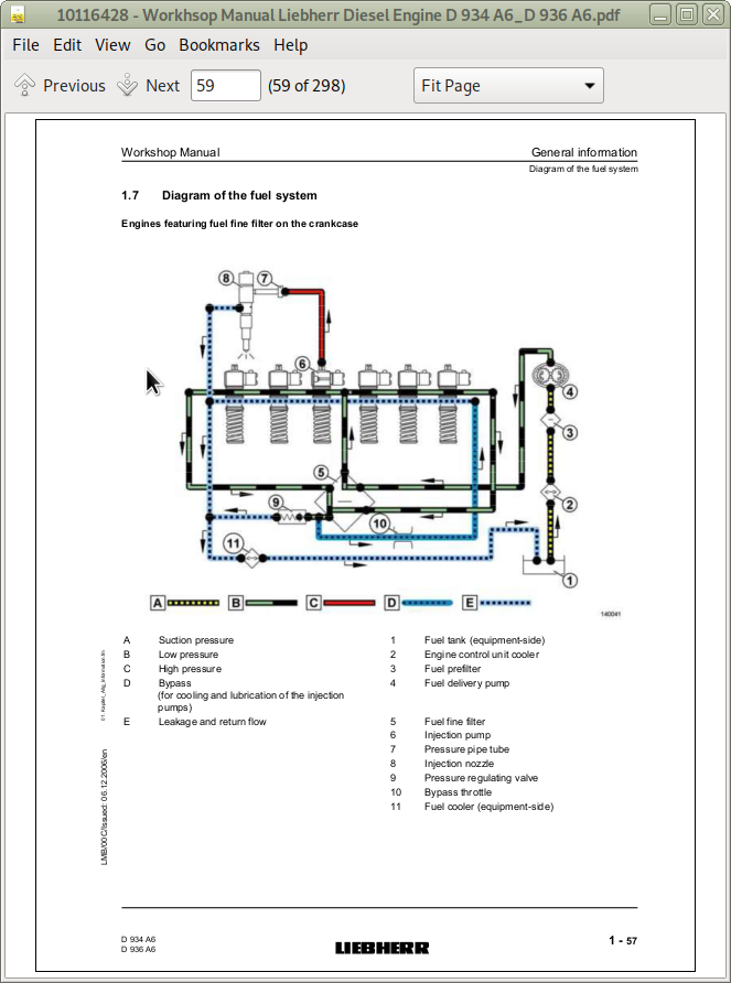
1.7 Diagram of the fuel system .. 1-57
1.8 Diagram of lube oil system .. 1-59
1.9 Diagram of coolant system .. 1-60
1.10 Allocation of ducts in the crankcase and in the cylinder head .. 1-62
1.11 Tools .. 1-63
Special tools .. 1-63
Fastening the engine onto the engine assembly stand .. 1-63
Fastening of lifting eyes on the crankcase .. 1-66
Turning gears .. 1-67
Angle of rotation devices .. 1-70
Checking excess length of the cylinder liners .. 1-73
Installing and dismantling crankshaft accessories .. 1-74
Installing and dismantling the front crankshaft seal.. 1-74
Installing and dismantling the crankshaft .. 1-74
Checking combustion pressure .. 1-74
Installing and dismantling the piston with connecting rod and piston rings .. 1-75
Installing and dismantling the piston rings.. 1-75
Installing and dismantling the cylinder head.. 1-75
Installing and dismantling valve stem seals, valve springs and valves .. 1-75
Installing and dismantling the counterbalancing shafts .. 1-77
Installing and dismantling the oil cooler housing with oil cooler .. 1-77
Installing and dismantling the injection lines .. 1-77
Installing and dismantling the pressure pipe tube and injection nozzle.. 1-78
Checking, dismantling and reassembling the injection nozzle (step-type holder) .. 1-78
Installing and dismantling the injection pump and roller tappet .. 1-78
Installing and dismantling the exhaust pipes .. 1-79
Installing and dismantling the flywheel .. 1-79
Installing and dismantling the rear crankshaft seal .. 1-79
Commercially-approved tools.. 1-80
Installing and dismantling the final regulating valve .. 1-80
Checking, dismantling and reassembling the injection nozzle (step-type holder) .. 1-80
Cylinder head, engine control and valves .. 2-81
2.1 Installing and dismantling the rocker arm support and push rods .. 2-82
2.2 Installing and dismantling the valve fitting (for engines with and without ZBS) .. 2-83
2.3 Installing and dismantling the cylinder head.. 2-84
2.4 Installing and dismantling valve stem seals, valve springs and valves .. 2-86
2.4.1 Removing .. 2-88
2.4.2 Installation .. 2-88
2.5 Installing and dismantling the roller tappet (valve control).. 2-90
2.6 Dismantling and installing the camshafts .. 2-91
2.6.1 Removing .. 2-92
2.6.2 Installation .. 2-93
Engine .. 3-95
3.1 Checking combustion pressure .. 3-97
3.2 Installing and dismantling the piston with connecting rod and piston rings .. 3-100
3.2.1 Summary .. 3-100
3.2.2 A: Installing and dismantling the piston with connecting rod from the engine .. 3-101
Removing .. 3-102
Installation .. 3-105
B: installing and dismantling the piston rings .. 3-107
Removing .. 3-108
Installation .. 3-108
C: installing and dismantling the piston .. 3-109
3.3 Installing and dismantling the cylinder liner .. 3-110
3.4 Checking excess length of the cylinder liners.. 3-112
3.5 Installing and dismantling the generator mount .. 3-113
3.6 Installing and dismantling the air-conditioning compressor and generator mount.. 3-115
3.7 Installing and dismantling crankshaft accessories.. 3-117
3.8 Installing and dismantling the front crankshaft seal .. 3-119
3.8.1 General notes.. 3-120
3.8.2 Removing .. 3-120
Installation .. 3-121
Installing and dismantling the aggregate carrier .. 3-125
3.10 Installing and dismantling the flywheel .. 3-127
3.10.1 Removing .. 3-130
3.10.2 Installation .. 3-130
3.11 Installing and dismantling the rear crankshaft seal.. 3-133
3.11.1 General notes .. 3-134
3.11.2 Removing .. 3-134
3.11.3 Installation .. 3-135
3.12 Dismantling and installing the flywheel housing .. 3-138
3.13 Dismantling and installing the idler .. 3-140
3.14 Installing and dismantling the crankshaft .. 3-142
3.14.1 Removing .. 3-145
3.14.2 Installation .. 3-148
3.15 Installing and dismantling the crankshaft gear wheel .. 3-151
4.1 Notes regarding working on the fuel system and injection system .. 4-154
4.2 Installing and dismantling fuel lines .. 4-155
4.3 Installing and dismantling the fuel prefilter with bracket .. 4-162
4.4 Installing and dismantling the fuel fine filter with bracket .. 4-163
4.5 Installing and dismantling the fuel multiplier .. 4-165
4.6 Installing and dismantling the fuel delivery pump .. 4-166
4.7 Installing and dismantling the injection lines.. 4-167
4.7.1 Removing .. 4-168
4.7.2 Installation .. 4-169
Installing and dismantling the pressure pipe tube and injection nozzle .. 4-170
4.8.1 Removing .. 4-171
4.8.2 Installation .. 4-172
Checking, dismantling and reassembling the injection nozzle (step-type holder).. 4-174
Check the injection nozzle.. 4-177
Check the opening pressure .. 4-178
Adjusting the opening pressure .. 4-178
Spray formation test and buzz test .. 4-180
Checking for leaks .. 4-180
Dismantling and reassembling the injection nozzle.. 4-181
4.10 Draining the fuel ducts in the crankcase.. 4-184
4.11 Installing and dismantling the injection pump and roller tappet .. 4-189
4.11.1 Removing .. 4-191
4.11.2 Installation .. 4-191
Belt drive .. 5-195
5.1 Installing and dismantling the ribbed V-belt tensioning device .. 5-196
5.2 Installing and dismantling the ribbed V-belt deflection pulley .. 5-197
Charge air and exhaust system .. 6-199
6.1 Installing and dismantling the air induction pipe .. 6-200
6.2 Installing and dismantling the connecting line (turbocharger - intercooler) .. 6-201
6.3 Installing and dismantling the exhaust pipes .. 6-205
6.4 Installing and dismantling the engine brake .. 6-207
6.5 Installing and dismantling the intake manifold .. 6-208
6.6 Installing and dismantling the adapter .. 6-209
6.7 Installing and dismantling the exhaust stack .. 6-210
6.8 Installing and dismantling the flange .. 6-211
6.9 Installing and dismantling the thermal protection plate on the exhaust pipe .. 6-212
6.10 Installing and dismantling the thermal protection plate on the turbocharger .. 6-213
6.11 Installing and dismantling the turbocharger .. 6-214
6.12 Checking axial clearance and radial clearance of the turbocharger .. 6-216
Electrical system .. 7-217
7.1 Installing and dismantling the heater flange .. 7-218
7.2 Installing and dismantling the generator .. 7-220
7.3 Installing and dismantling the generator belt pulley.. 7-221
7.4 Installing and dismantling the starter .. 7-223
7.5 Installing and dismantling the sensors.. 7-224
7.6 Installing and dismantling the engine control unit .. 7-226
7.7 Installing and dismantling the engine control unit-mount.. 7-228
Lubrication system .. 8-233
8.1 Installing and dismantling the crankcase breather .. 8-234
8.2 Installing and dismantling the oil return-flow line (crankcase breather) .. 8-236
8.3 Installing and dismantling the oil dipstick and guide tube .. 8-237
8.4 Installing and dismantling the oil intake .. 8-238
8.5 Installing and dismantling the multi-part oil sump and ladder frame (D 936) .. 8-240
8.6 Installing and dismantling the single-unit oil sump.. 8-246
8.7 Installing and dismantling the connector (oil sump - crankcase) (D 934) .. 8-250
8.8 Installing and dismantling the oil suction pipe (D 936).. 8-251
8.9 Installing and dismantling the ladder frame .. 8-252
8.10 Installing and dismantling the oil cooler housing with oil cooler.. 8-253
8.11 Dismantling and installing the oil pressure pump .. 8-255
8.12 Installing and dismantling the oil suction pump (D 936) .. 8-257
8.13 Installing and dismantling the piston cooling nozzle .. 8-258
8.14 Dismantling and installing the sealing parts of the oil suction pump.. 8-260
8.15 Installing and dismantling the final regulating valve.. 8-261
8.16 Check the oil pressure, adjust as necessary .. 8-264
Cooling system .. 9-267
9.1 Installing and dismantling the coolant vent line .. 9-268
9.2 Installing and dismantling the coolant pump .. 9-269
9.3 Installing and dismantling the coolant manifold (on the thermostat housing or aggregate carrier) .. 9-271
9.4 Installing and dismantling the thermostat housing and thermostat .. 9-273
9.5 Checking the thermostat .. 9-274
Power take-off and air / air-conditioning compressor .. 10-277
10.1 Installing and dismantling the power take-off for fuel delivery pump .. 10-278
10.2 Dismantling and removing power take-off 1 .. 10-279
10.3 Dismantling and removing power take-off 2 .. 10-281
10.4 Dismantling and removing power take-off 3 .. 10-282
10.6 Installing and removing the power take-off on the flywheel housing .. 10-285
10.6.1 Removing .. 10-286
10.6.2 Installation .. 10-287
10.7 Dismantling and installing the switchable power take-off on the flywheel housing .. 10-289
10.7.1 Removing .. 10-290
10.7.2 Installation .. 10-291
10.8 Installing and dismantling the air-conditioning compressor .. 10-293
![]()