
John Deere 7, 8, 8A, 8B, 10, 10A, 46, 47, 48, 260, 260B, 270A, 270B, 375, 375A, 385A, 447, 448, 485 and 485A Backhoes Diagnostic and Repair Service Manual (TM2213)
Complete All Inclusive Technical Manual with electrical wiring diagrams for John Deere 7, 8, 8A, 8B, 10, 10A, 46, 47, 48, 260, 260B, 270A, 270B, 375, 375A, 385A, 447, 448, 485 and 485A , with all the shop information to maintain, diagnose, and service like professional mechanics (Diagnosis, Operation, Tests, Repair, Service, Troubleshooting).
John Deere 7, 8, 8A, 8B, 10, 10A, 46, 47, 48, 260, 260B, 270A, 270B, 375, 375A, 385A, 447, 448, 485 and 485A workshop technical service manual includes:
* Numbered table of contents easy to use so that you can find the information you need fast.
* Detailed sub-steps expand on repair procedure information
* Numbered instructions guide you through every repair procedure step by step.
* Troubleshooting and electrical service procedures are combined with detailed wiring diagrams for ease of use.
* Notes, cautions and warnings throughout each chapter pinpoint critical information.
* Bold figure number help you quickly match illustrations with instructions.
* Detailed illustrations, drawings and photos guide you through every procedure.
* Enlarged inset helps you identify and examine parts in detail.
tm2213 - 7, 8, 8A, 8B, 10, 10A, 46, 47, 48, 260, 260B, 270A, 270B, 375, 375A, 385A, 447, 448, 485 and 485A Backhoes Technical Manual.pdf
Total Pages: 303 pages
File Format: PDF (PC/Mac/Android/Kindle/iPhone/iPad; bookmarked, ToC, Searchable, Printable)
Language: English
tm2213 - 7, 8, 8A, 8B, 10, 10A, 46, 47, 48, 260, 260B, 270A, 270B, 375, 375A, 385A, 447, 448, 485 and 485A Backhoes
Table of Contents
Foreword
Section 00: General Information
Group 05A: Safety
Recognize Safety Information
Handle Fuel Safely—Avoid Fires
Prevent Battery Explosions
Prepare for Emergencies
Prevent Acid Burns
Service and Operate Chemical Sprayers Safely
Handle Chemical Products Safely
Avoid High-Pressure Fluids
Park Machine Safely
Support Machine Properly
Wear Protective Clothing
Work in Clean Area
Service Machines Safely
Work In Ventilated Area
Illuminate Work Area Safely
Replace Safety Signs
Use Proper Lifting Equipment
Remove Paint Before Welding or Heating
Avoid Heating Near Pressurized Fluid Lines
Keep ROPS Installed Properly
Service Tires Safely
Avoid Harmful Asbestos Dust
Practice Safe Maintenance
Use Proper Tools
Decommissioning — Proper Recycling and Disposal of Fluids and Components
Prevent Machine Runaway
Handle Starting Fluid Safely
Service Cooling System Safely
Stay Clear of Rotating Drivelines
Protect Against High Pressure Spray
Construct Dealer-Made Tools Safely
Clean Vehicle of Hazardous Pesticides
Servicing Electronic Control Units
Welding Near Electronic Control Units
Keep Electronic Control Unit Connectors Clean
Live With Safety
Group 05B: General References
Interlock System
Metric Bolt and Screw Torque Values
Metric Cap Screw Torque Values—Grade 7
Unified Inch Bolt and Screw Torque Values
Service Recommendations For Flat Face O-Ring Seal Fittings
Service Recommendations for O-Ring Boss Fittings
Group 05C: Technical Specifications
Hydraulic Specifications
Torque Specifications
Group 05D: Fuels and Lubricants
Alternative Lubricants
Synthetic Lubricants
Lubricant Storage
Mixing of Lubricants
Chassis Grease
Group 05E: Serial Number Locations
Machine Product Identification Number
Section 100: Repair
Group 10: Restrictor Repair
Restrictor Inspection - 260, 270A and 270B
Restrictor Inspection - 7, 8, 8A, 8B, 10, 10A, 46, 47 and 48
Restrictor Inspection - 375, 375A, 385A, 447, 448, 485 and 485A
Group 15: System Relief Valve Inspection
System Relief Valve Inspection - 7, 8, 8A, 8B, 10A, 46, 47 and 48
System Relief Valve Inspection - 260 and 270A
System Relief Valve Inspection - 260B and 270B
System Relief Valve Inspection - 375, 375A, 385A, 447, 448, 485 and 485A
Group 20: Control Spool Repair
Spool Disassembly and Assembly - 7, 8, 8A, 8B, 10, 10A, 46, 47 and 48
Spool Disassembly and Assembly - 375, 375A, 385A, 447, 448, 485 and 485A
Group 25: Load Check Valve Inspection
Load Check Valves Inspection - 7, 8, 8A, 8B, 10, 10A, 46, 47 and 48 Model
Load Check Valves Inspection - 375, 375A, 385A, 447, 448, 485, and 485A Models
Load Check Valves Inspection - 260, 270A and 270B Models
Group 30: Dipperstick Circuit Relief Valve Inspection
Dipperstick Circuit Relief Valve Inspection - 7, 8, 8A, 8B, 10, 10A, 46, 47 and 48
Group 35: Anti-Cavitation Valve Inspection
Anti-Cavitation Valve Inspection - 7, 8, 8A, 8B, 10, 10A, 46, 47 and 48
Group 40: Buck/Boom Relief Valve Inspection
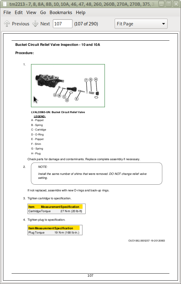
Bucket Circuit Relief Valve Inspection - 10 and 10A
Boom Circuit Relief Valve Inspection - 7, 8, 8A, 8B, 10, 10A, 46, 47 and 48
Boom and Dipperstick Circuit Relief Valve - 260 and 270A
Boom, Dipperstick, and Swing Circuit Relief Valve - 260B and 270B
Boom and Dipperstick Circuit Relief Valve with Anti-Cavitation Check Inspection - 375, 375A, 447, 448 and 485
Boom, Dipperstick, and Swing Circuit Relief Valve with Anti-Cavitation Check Inspection - 385A and 485A
Group 45: Valve Housing/Block Repair
Valve Housing Removal and Installation - 7, 8, 8A, 8B, 10 and 10A Models
Valve Housing Removal and Installation - 46, 47, and 48 Models
Valve Housing Disassembly and Repair - 7, 8, 8A, 8B, 10, 10A, 46, 47 and 48
Valve Housing Removal and Installation - 260, 260B, 270A, and 260B
Valve Housing Disassembly and Repair - 260 and 270A
Valve Housing Disassembly and Repair - 260B and 270B
Valve Housing Removal and Installation - 375, 375A, 385A, 447, 448, 485 and 485A Models
Valve Housing Disassembly and Assembly - 375, 375A, 385A, 447, 448, 485 and 485A
Group 50: Cross Over Relief Valve Repair
Crossover Relief Valve Disassembly and Repair - 7, 8, 8A, 8B, 10, and 10A
Group 55: Valve Linkage Inspections
Valve Linkage Inspection - 7, 8, 8A, 8B, 10 and 10A
Valve Linkage Inspection - 46
Valve Linkage Inspection - 47
Valve Linkage Inspection - 48
Valve Linkage Inspection - 260B
Valve Linkage Inspection - 260, 270A and 270B
Valve Linkage Inspection - 375, 375A, 385A, 447, 448, 485 and 485A
Group 60: Cylinder Repair
Boom Cylinder Removal and Installation
DipperStick Cylinder Removal and Installation
Bucket Cylinder Removal and Installation
Stabilizer Cylinder Removal and Installation
Swing Cylinder Removal and Installation
Bucket, Boom and Dipperstick Cylinders Disassembly and Repair - 8, 8A, and 8B
Bucket, Boom and Dipperstick Cylinders Disassembly and Repair - 7 and 46
Bucket And Dipperstick Cylinders Disassembly and Repair - 10 and 10A
Boom Cylinder Disassembly and Repair - 10 and 10A
Boom And Dipperstick Cylinders Disassembly and Repair - 47
Bucket Cylinder Disassembly and Repair - 47 and 447
Stabilizer Cylinders Disassembly and Repair - 8, 8A, 8B, 10 and 10A
Stabilizer Cylinders Disassembly and Repair - 7, 46, 47, 260, 270A, 375, 375A and 447
Stabilizer Cylinders Disassembly and Repair - 260B and 270B
Swing Cylinders Disassembly and Repair - 7
Swing Cylinders Disassembly and Repair - 8, A, 8B, 10 and 10A
Swing Cylinders Disassembly and Repair - 46, 47, 375, 375A, 385A, 447 and 485A
Bucket, Boom, and Dipperstick Cylinders Disassembly and Repair - 48
Stabilizer Cylinders Disassembly and Repair - 48
Swing Cylinders Disassembly and Repair - 48
Dipperstick Cylinder Disassembly and Repair - 375, 447, 448 and 485
Bucket and Boom Cylinders Disassembly and Repair - 375 and 447—Bucket Cylinder Disassembly and Repair - 375A
Bucket and Boom Cylinders Disassembly and Repair - 448 and 485
Dipper Cylinders Disassembly and Repair - 375A, 384A and 485A
Boom Cylinders Disassembly and Repair - 375A, 384A and 485A
Stabilizer Cylinders Disassembly and Repair - 385A, 448, 485 and 485A
Swing Cylinders Disassembly and Repair - 448 and 485
Dipperstick Cylinder Disassembly and Repair - 260 and 270A
Dipperstick Cylinder Disassembly and Repair - 260B and 270B
Bucket Cylinder Disassembly and Repair - 260 and 270A
Bucket Cylinder Disassembly and Repair - 260B and 270B
Swing Cylinder Disassembly and Repair - 260B and 270B
Boom Cylinder Disassembly and Repair - 260 and 270A
Boom Cylinder Disassembly and Repair - 260B and 270B
Section 200: Diagnostics
Group 10: Troubleshooting
Use These Basic Steps to Diagnose and Test the Hydraulic System
Hydraulic System Pretest
Hydraulic Oil Warm-Up Procedure
System Check
Diagnostics
Group 20: Theory of Operations
Control Valves
Load Check Valves
Main System Relief Valve
Circuit Relief And Anti-Cavitation Check Valves
Restrictors
Group 30: Schematics
7, 8, 8A, 8B, 10 and 10A Backhoe Hydraulic System
46, 47 and 48 Backhoe Hydraulic System
260 and 270A Backhoe Hydraulic System
260B and 270B Backhoe Hydraulic System
375, 375A and 447 Backhoe Hydraulic System
385A and 485A Backhoe Hydraulic System
448 and 485 Backhoe Hydraulic System
Group 40: Component Locations
46 Boom
46 Swing Assembly and Stabilizer
46 Subframe and Mounting
47 Boom
48 Boom
260 Subframe and Mounting
260 and 270A Boom
260 and 270A Swing Assembly and Stabilizer
270A Subframe and Mounting
260B and 270B Component Location
375 Operator Platform
375A Component Location
375, 375A and 447 Swing Assembly
375, 375A and 447 Boom
385A, 448, 485 and 485A Swing Assembly
385A, 448, 485 and 485A Boom
385A Component Location
447 Operator Platform
448 and 485 Operator Platform
485A Component Location
Group 50: Tests and Adjustments
Circuit Relief Valve Pressure Tests
Main System Pressure Relief Valve Test
Crossover Relief Valve Test - 7, 8, 8A, 8B and 10A
Rockshaft Height Adjustment (Mid-Chassis)
Rockshaft Height Adjustment (Large Chassis)
John Deere 7, 8, 8A, 8B, 10, 10A, 46, 47, 48, 260, 260B, 270A, 270B, 375, 375A, 385A, 447, 448, 485 and 485A Backhoes Diagnostic and Repair Service Manual (TM2213)
![]()