
John Deere XUV Gator Utility Vehicle 825i S4 Repair & Service Technical Manual + Operator's Manual (TM121519 & OMM165093)
Complete service manual + operator's manual with Electrical Wiring Diagrams for John Deere XUV Gator Utility Vehicle 825i S4, with all the shop information to maintain, diagnose, repair, and rebuild like professional mechanics.
John Deere XUV Gator Utility Vehicle 825i S4 workshop service repair manual includes:
* Numbered table of contents easy to use so that you can find the information you need fast.
* Detailed sub-steps expand on repair procedure information
* Numbered instructions guide you through every repair procedure step by step.
* Troubleshooting and electrical service procedures are combined with detailed wiring diagrams for ease of use.
* Notes, cautions and warnings throughout each chapter pinpoint critical information.
* Bold figure number help you quickly match illustrations with instructions.
* Detailed illustrations, drawings and photos guide you through every procedure.
* Enlarged inset helps you identify and examine parts in detail.
John Deere XUV Gator Utility Vehicle 825i S4 Repair & Service Technical Manual + Operator's Manual (TM121519 & OMM165093)
TM121519 - XUV Gator Utility Vehicle 825i S4 Technical Manual.pdf
TM121519 - XUV Gator Utility Vehicle 825i S4 Technical Manual.epub
OMM165093 H1 - XUV Gator Utility Vehicle 825i Operator's Manual.pdf
Total Pages: 1,390 + 96 pages
File Format: PDF/EPUB/MOBI/AZW (PC/Mac/Android/Kindle/iPhone/iPad; bookmarked, ToC, Searchable, Printable)
Language: English
tm107119 - XUV Gator Utility Vehicle 825i
Table of Contents
Foreword
Section 10: Safety
Group 05: Safety
Recognize Safety Information
Understand Signal Words
Replace Safety Signs
Handle Fluids Safely—Avoid Fires
Prepare for Emergencies
Prevent Battery Explosions
Prevent Acid Burns
Wear Protective Clothing
Avoid High-Pressure Fluids
Avoid Heating Near Pressurized Fluid Lines
Service Machines Safely
Use Proper Tools
Park Machine Safely
Support Machine Properly
Use Proper Lifting Equipment
Work in Clean Area
Protect Against High Pressure Spray
Illuminate Work Area Safely
Work In Ventilated Area
Remove Paint Before Welding or Heating
Avoid Harmful Asbestos Dust
Service Tires Safely
Stay Clear of Rotating Drivelines
Service Cooling System Safely
Decommissioning — Proper Recycling and Disposal of Fluids and Components
Handle Chemical Products Safely
Live With Safety
Section 20: Specifications
Group 05: Specifications
Metric Bolt and Screw Torque Values
Unified Inch Bolt and Screw Torque Values
Group 10: O-Ring Seal Service Recommendations
Service Recommendations for O-Ring Boss Fittings
Service Recommendations For Flat Face O-Ring Seal Fittings
Metric Cap Screw Torque Values—Grade 7
Group 15: General Information
Gasoline
Gasoline Storage
4 - Cycle Gasoline Engine Oil
Break-In Engine Oil - 4-Cycle Gasoline
Transaxle Oil
EMFWD Differential Oil
Alternative Lubricants
Synthetic Lubricants
Lubricant Storage
Mixing of Lubricants
Oil Filters
Brake Fluid
Chassis Grease
Group 20: Coolant
Recommended Engine Coolant
Group 25: Serial Number Locations
Product Serial Number
Section 30: Engine – Gas
Group 05: Specifications
Specifications
Essential or Recommended Tools
Other Material
Group 10: Component Location
Engine Intake
Engine Exhaust
Engine Mounting
Coolant System
Engine Coolant Lines (SN -080000)
Engine Coolant Lines (SN 080001-)
Engine Block and Head
Engine Crankshaft and Pistons
Engine Valve Train
Group 15: Diagnostics
Starting Diagnosis
Engine Performance Diagnosis
Engine Coolant Diagnosis
Fuel and Oil Diagnosis
Group 20: Tests and Adjustments
Throttle Cable Adjustment
Idle Speed Check
Fuel Pump/Regulator Pressure Test
Cylinder Leak-Down Test
Crankcase Vacuum Test
Valve Clearance Adjustment
Oil Pressure Test
Radiator Cap Pressure Test
Thermostat Test
Group 25: Repair
Remove and Install Engine
Remove and Install Valve Cover
Timing Belt Removal and Installation
Water Pump Remove and Install
Remove and Install Cylinder Head
Remove and Install Intake Manifold
Exhaust Manifold Removal and Installation
Recondition Cylinder Head
Remove and Install Oil Pan
Remove and Install Oil Pump
Remove and Install Crankshaft Front Oil Seal
Remove and Install Camshafts
Check Crankshaft Main Bearing Clearance
Check Connecting Rod Bearing Clearance
Check Connecting Rod Side Play
Repair Piston and Connecting Rod
Repair Piston
Cylinder Bore
Remove and Install Crankshaft and Main Bearings
Remove and Install Crankshaft Rear Oil Seal
Alternator Removal and Installation
Starting Motor Removal and Installation
Fuel Injector Replacement
Exhaust Gas Oxygen Sensor Replacement
Knock Sensor Replacement
Camshaft Position Sensor Replacement
Crankshaft Position Sensor Replacement
Intake Manifold Pressure/Temperature Sensor Replacement
Throttle Body Replacement
Section 40: Electrical
Group 05: General Information
Operation and Diagnostics
Diagnostic Information
Wire Color Abbreviation Chart
Reading Electrical Schematics
Common Circuit Tests
Conductors for 12 Volt Circuits
Group 10: Specifications
Specifications
Service Equipment and Tools
Other Material
Group 15: Component Location
Summary of References
ECU Pin Locations
VCU Pin Locations (SN -060000)
VCU Pin Locations (SN 060001-)
Fuse Block Components (SN -060000)
Load Center (SN 060001-)
Load Center Components (SN 060001-)
Group 20: Schematics and Harnesses (SN -060000)
Main Schematic and Wiring Harness Legend (SN -060000)
Main Electrical Schematic (SN -060000)
Ground Circuits (SN -060000)
Main Wiring Harness (SN -060000)
Main Wiring Harness Color Codes (SN -060000)
Engine Wiring Harness (SN -060000)
Engine Wiring Harness Color Codes (SN -060000)
Group 25: Schematics and Harnesses (SN 060001-100000)
Summary of References
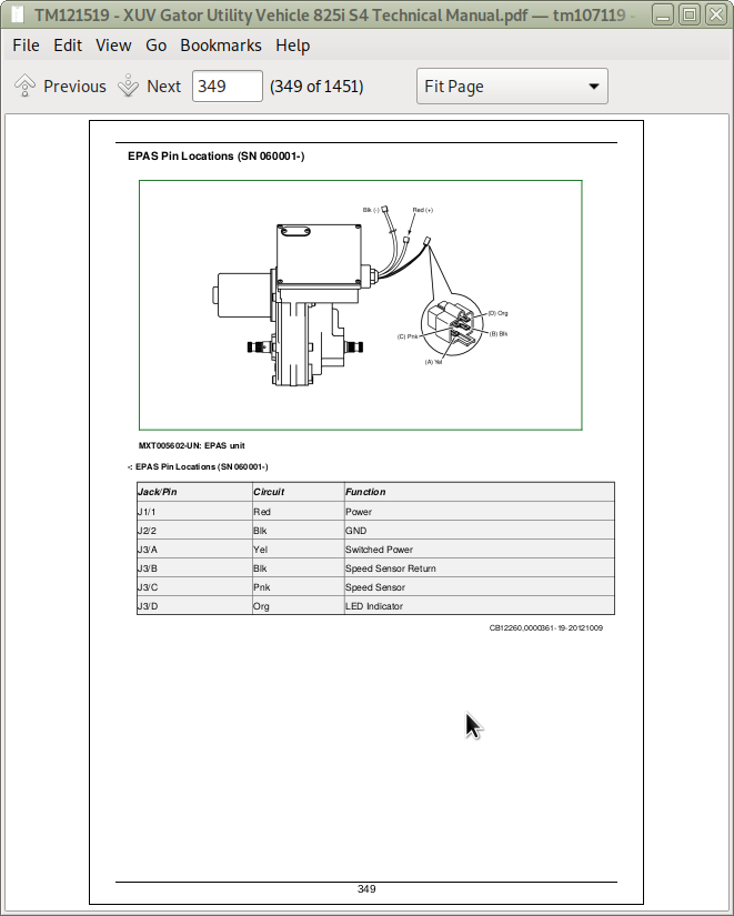
EPAS Pin Locations (SN 060001-)
Display Panel Pin Locations (SN 060001-)
Schematic and Wiring Harness Legend (SN 060001-)
Main Electrical Schematic (SN 060001-080000)
Main Electrical Schematic (SN 080001-100000)
Ground Circuits (SN 060001-080000)
Ground Circuits (SN 080001-100000)
Main Wiring Harness (SN 060001-080000)
Main Wiring Harness Color Codes (SN 060001-080000)
Main Wiring Harness (SN 080001-100000)
Main Wiring Harness Color Codes (SN 080001-100000)
Engine Wiring Harness (SN 060001-100000)
Engine Wiring Harness Color Codes (SN 060001-100000)
Group 30: Schematics and Harnesses (SN 100001-)
Summary of References
Main Wiring Harness (SN 100001-103657)
Main Wiring Harness (SN 103658-)
Main Wiring Harness Color Codes (SN 100001-)
Main Wiring Harness Splice Table (SN 100001-)
Main Wiring Harness Terminal Table (SN 100001-)
Main Electrical Schematic (SN 100001-103657)
Main Electrical Schematic (SN 103658-)
Engine Wiring Harness (SN 100001-)
Engine Wiring Harness Color Codes (SN 100001-)
Ground Circuits (SN 100001-)
Group 35: MFWD Service Kit Operation, Schematics, and Harnesses
Summary of References
Electrical Operation and Schematic (AM145249)
Wiring Harness AM145249
Electrical Operation and Schematic (AM146628)
Wiring Harness AM146628
Electrical Operation and Schematic (AM147221)
Wiring Harness AM147221
Group 40: Electrical Kits Schematics and Harnesses
Lights Wiring Harness, AM140950
Lights Wiring Schematic, AM140950
Headlight Jumper Wiring Harness, AM147740
Lights Wiring Harness, AM137558
Lights Wiring Schematic, AM137558
Turn Signal with Flasher Harness, AM143722
Turn Signal with Flasher Schematic, AM143722
Taillight Harness, AM137737
Taillight Schematic, AM137737
Trailer Connector Wiring Harness
Backup Alarm Wiring Harness, AM144181
Backup Alarm Wiring Schematic, AM144181
Cab Power Splitter Wiring Harness, AM140972
Canopy Wiring Harness, AM143139
Canopy Wiring Schematic, AM143139
Roof Work Lights Wiring Harness, AM146905
Roof Work Lights Wiring Schematic, AM146905
Beacon Light Wiring Harness, AM140971
Beacon Light Wiring Schematic, AM140971
Horn Wiring Harness, VGA10903
Horn Wiring Schematic, VGA10903
OPS Rear Lights Wiring Harness, AM146376
OPS Rear Lights Wiring Schematic, AM146376
Winch Main Wiring Harness, AM144137
Winch Control Wiring Harness, AM142263
Winch Schematic
Group 45: Operation and Diagnostics (SN -060000)
Power Circuit Operation (SN -060000)
Power Circuit Diagnosis (SN -060000)
Cranking Circuit Operation (SN -060000)
Cranking Circuit Electrical Schematic (SN -060000)
Cranking Circuit Diagnosis (SN -060000)
Charging Circuit Operation (SN -060000)
Charging Circuit Electrical Schematic (SN -060000)
Charging Circuit Diagnosis (SN -060000)
Hour Meter Circuit Operation (SN -060000)
Speedometer Circuit Operation (SN -060000)
Tachometer Circuit Operation (SN -060000)
Hour Meter/Speedometer/Tachometer Circuit Electrical Schematic (SN -060000)
Seat Belt Circuit Operation (SN -060000)
Seat Belt Circuit Electrical Schematic (SN -060000)
Seat Belt Electrical Circuit Diagnosis (SN -060000)
Park Brake Light and Warning Buzzer Circuit Operation (SN -060000)
Park Brake and Warning Buzzer Circuit Electrical Schematic (SN -060000)
Park Brake and Warning Buzzer Circuit Diagnosis (SN -060000)
Oil Pressure Light Circuit Operation (SN -060000)
Cooling Circuit Operation (SN -060000)
Cooling Circuit Electrical Diagnosis (SN -060000)
Cooling Circuit Electrical Schematic (SN -060000)
4WD Drive Circuit Operation (EMFWD) (SN -060000)
4WD Circuit Electrical Schematic (SN -060000)
4WD Electrical Circuit Diagnostics (SN -060000)
Light Circuit Operation (SN -060000)
Headlight Circuit Diagnosis (SN -060000)
Electronic Controller Power Flow Operation (SN -060000)
Electronic Controller Power Flow Circuit Schematic (SN -060000)
Vehicle Control Unit (VCU) Power Diagram (SN -060000)
Troubleshooting Electronic Controllers (SN -060000)
On Board Diagnostics (SN -060000)
Group 50: Operation and Diagnostics - Fuel Injection
Summary of References
Temperature/Mass Air Pressure (TMAP) Sensor Circuit Operation
Throttle Position Sensor (TPS)
Coolant Temperature Sensor Circuit Operation
Knock Sensor Circuit Operation
Oxygen Sensor (O2) Circuit Operation
Idle Air Control Motor (IAC) Circuit Operation
Ignition Coil Operation
Fuel Injector Operation
Fuel Pump Operation
Malfunction Indicator Light (MIL) Operation
Diagnostic Interface Circuit Operation
ECU and General Sensor Circuit Operation
ECU Sensor and Diagnostic Circuit Diagnosis
Fuel Injection Circuit Electrical Schematic (SN -060000)
Fuel Injection Circuit Electrical Schematic (SN 060001-)
Group 55: Operation and Diagnostics - DTCs
Error Codes List
Error Codes Description
P0031 - O2 Sensor Heater Circuit Low (Bank 1 Sensor 1)
P0032 - O2 Sensor Heater Circuit High (Bank 1 Sensor 1)
P0107 - Manifold Absolute Pressure Circuit Low
P0108 - Manifold Absolute Pressure Circuit High
P0112 - Intake Air Temperature Circuit Low Input
P0113 - Intake Air Temperature Circuit High Input
P0116 - Engine Coolant Temperature Circuit Range/Performance Problem
P0117 - Engine Coolant Temperature Circuit Low Input
P0118 - Engine Coolant Temperature Circuit High Input
P0119 - Engine Coolant Temperature Circuit Intermittent
P0122 - Throttle/Pedal Position Circuit Input Low
P0123 - Throttle/Pedal Position Circuit Input High
P0130 - O2 Sensor Circuit Malfunction (Bank 1 Sensor 1)
P0131 - O2 Sensor Circuit Low Voltage (Bank 1 Sensor 1)
P0132 - O2 Sensor Circuit High Voltage (Bank 1 Sensor 1)
P0134 - O2 Sensor No Activity Detected (Bank 1 Sensor 1)
P0230 - Fuel Pump Circuit Malfunction
P0261 - Cylinder 1 - Injector Circuit Low
P0262 - Cylinder 1 - Injector Circuit High
P0264 - Cylinder 2 - Injector Circuit Low
P0265 - Cylinder 2 - Injector Circuit High
P0267 - Cylinder 3 - Injector Circuit Low
P0268 - Cylinder 3 - Injector Circuit High
P0325 - Knock Sensor 1 Circuit Malfunction
P0335 - Crankshaft Position Sensor Malfunction
P0340 - Camshaft Position Sensor Malfunction
P0351 - Ignition Coil ‘A’ Primary Secondary Circuit Malfunction
P0352 - Ignition Coil ‘B’ Primary Secondary Circuit Malfunction
P0353 - Ignition Coil ‘C’ Primary Secondary Circuit Malfunction
P0505 - Idle Speed Actuator Command Signal Incorrect
P0506 - Idle Air Control System - RPM Lower Than Expected
P0507 - Idle Air Control System - RPM Higher Than Expected
P0560 - System Voltage Problem
P0605 - Internal Control Module Read Only Memory (ROM) Error
P0650 - Malfunction Indicator Lamp (MIL) Control Circuit
P1166 - O2 Sensor - Controller Adaptation Diagnosis Malfunction
P1624 - Cooling Fan Relay - Circuit Malfunction - “Low” Circuit
P1625 - Cooling Fan Relay - Circuit Malfunction - “High” Circuit
Group 60: Operation and Diagnostics (SN 060001-)
Summary of References
Power Circuit Operation (SN 060001-080000)
Power Circuit Operation (SN 080001-100000)
Power Circuit Operation (100001-)
Power Circuit Diagnosis (SN 060001-)
Cranking Circuit Operation (SN 060001-)
Cranking Circuit Diagnosis (SN 060001-)
Charging Circuit Operation (SN 060001-)
Charging Circuit Diagnosis (SN 060001-)
Hour Meter Circuit Operation (SN 060001-)
Speedometer Circuit Operation (SN 060001-)
Tachometer Circuit Operation (SN 060001-)
Fuel Level Circuit Operation (SN 060001-)
Seat Belt Circuit Operation (SN 060001-)
Seat Belt Circuit Diagnosis (SN 060001-)
Park Brake Light and Warning Buzzer Circuit Operation (SN 060001-)
Park Brake Light and Warning Buzzer Circuit Diagnosis (SN 060001-)
Oil Pressure Light Circuit Operation (SN 060001-)
Cooling Circuit Operation (SN 060001-)
Cooling Circuit Electrical Diagnosis (SN 060001-)
4WD Drive Circuit Operation (EMFWD) (SN 060001-080000)
4WD Drive Circuit Diagnosis (EMFWD) (SN 060001-080000)
4WD Drive Circuit Operation (EMFWD) (SN 080001-100000)
4WD and Speedometer Circuit Operation (SN 100001-)
Light Circuit Operation (SN 060001-080000)
Light Circuit Diagnosis (SN 060001-080000)
Light Circuit Operation (SN 080001-)
Electronic Controller Power Flow Operation (SN 060001-)
Group 65: Operation and Diagnostics - Electronic Controllers (SN 060001-)
Summary of References
Troubleshooting Electronic Controllers (SN 060001-)
On Board Diagnostics - ECU (SN 060001-)
On Board Diagnostics - Relay Module (SN 060001-100000)
On Board Diagnostics - VCU (SN 100001-)
Vehicle Control Unit/Relay Module (VCU) Operation (SN 060001-100000)
Vehicle Control Unit (VCU) Operation (SN 100001-)
ECU and General Sensor Circuit Operation (SN 060001-100000)
ECU Sensor and Diagnostic Circuit Diagnosis (SN 060001-)
ECU and General Sensor Circuit Operation (100001-)
Display Panel Operation (SN 060001-)
Display Panel Replacement Programming (SN 060001-100000)
Display Panel Replacement Programming (SN 100001-)
Display Panel Tire Size Programming (SN 060001-)
Overtemp Input (SN 060001-)
Oil Pressure Input (SN 060001-)
Coolant Temperature Gauge (SN 060001-)
Fuel Level (SN 060001-)
Tachometer (SN 060001-100000)
Tachometer (SN 100001-)
Speedometer (SN 060001-)
Electric Power Assist Steering (EPAS) Operation (SN 060001-)
EPAM Test (SN 060001-)
Live Readings (SN 060001-)
Approved Software for Control Units
Erroneous Diagnostic Trouble Codes (SN 060001-)
Group 70: Tests and Adjustments
Summary of References
Ground Circuit Test
Battery Test
Charge Battery
Load Test Battery
Clean Battery
Regulated Voltage Output Test
Starter Loaded Amperage Draw Test
Starter No-Load Amperage and RPM Test
Key Switch Test
Park Brake Switch Test
Neutral Start Switch Test
Reverse Switch Test
Headlight Switch Test (Single)
Headlight Switch Test (2 Position) (AM144577)
Light Switch Test (3-position)
4WD Switch Test
4WD Switch Test (AM142314)
Throttle Switch Test
Brake Lights Switch Test
Raise/Lower Switch Test
Raise/Lower Switch Test (AM142315)
Engine Coolant Temperature Sensor Test
Engine Oil Pressure Switch Test
Seat Belt Switch Test
Fuse Test
Bulb Test
Diode Test
Relay Test
Speed Sensor Test
4WD Solenoid Test
Warning Alarm Test
Idle Air Control Test
Ignition Coil Test
Fuel Injector Test
Knock Sensor Test
Fuel Pump Relay Command Test (SN 060001-)
Cooling Fan Relay High Command Test (SN 060001-)
Cooling Fan Relay Low Command Test (SN 060001-)
Main Relay Command Test (SN 060001-)
Cylinder Shut-off Command Test (SN 060001-)
Ignition Coil 1 Command Test (SN 060001-)
Ignition Coil 2 Command Test (SN 060001-)
Ignition Coil 3 Command Test (SN 060001-)
Section 50: Power Train
Group 05: Specifications
Specifications
Essential or Recommended Tools
Other Material
Group 10: Component Location
Power Train Components
Front Axle
Rear Axle
MFWD Driveline
Front Drive Gear Box
EMFWD Front Differential Components
Transaxle, Gear
Differential
Transaxle Input (SN -060000)
Transaxle Input (SN 060001-)
Shift Linkage
Primary Clutch (SN -060000)
Primary Clutch (SN 060001-)
Secondary Clutch (SN -060000)
Secondary Clutch (SN 060001-)
Transmission Mounts
Group 15: Theory of Operation
Power Transfer Operation
Drive Clutch Operation (SN -060000)
Drive Clutch Operation (SN 060001-)
Clutch Operation (SN -060000)
Clutch Operation (SN 060001-)
EMFWD Operation
MFWD Anti-Wedging (SN -100000)
Group 20: Diagnostics
Diagnose Drivetrain
Diagnose Engine Primary Clutch
Diagnose Primary and Secondary Clutch
Group 25: Tests and Adjustments
Summary of References
Differential Lock Adjustment
Transmission Shift Adjustment
Clutch Sheave Alignment (SN 060001-)
Group 30: Repair
Summary of References
Essential or Recommended Tools
Changing Transmission Oil
Changing EMFWD Front Differential Oil
Cleaning Primary Drive Clutch
Clutch Removal and Installation (SN -060000)
Clutch Removal (SN 060001-)
Clutch Installation (SN 060001-)
Primary Drive Clutch Repair (SN -060000)
Primary Drive Clutch Repair (SN 060001-)
Driven Clutch Disassembly and Assembly (SN -060000)
Driven Clutch Disassembly and Assembly (SN 060001-)
Transmission Removal
Transmission Installation
Transmission Disassembly
Transmission Assembly
Front Drive Gearbox Disassembly and Assembly
EMFWD Driveshaft Removal and Installation
EMFWD Driveshaft Boot Replacement
Front Differential Removal and Installation
Front Differential Disassembly
Front Differential Assembly
Rear Axle Halfshaft Removal and Installation
Front Axle Halfshaft Removal and Installation
CV Joint and Boots - Front Axle Halfshafts
CV Joint and Boots - Rear Axle Halfshafts
Hub Removal
Hub Installation
Section 60: Steering
Group 10: Component Location
Steering Components
Steering Components With EPAS
Front Suspension
Front Suspension
Rear Suspension
Rear Suspension
Group 15: Theory of Operation
Steering
Electric Power Assisted Steering (EPAS)
Group 20: Diagnosis
Steering Pulls In One Direction
Steering Wanders or Vibrates
Wheel Bearing Noise
Steering Hard in Left, Right, or Both Directions
Steering Locks In Hard Left or Right Turn
Steering Wheel Pulls Upward
Steering Wheel Spins Freely
Noise During Turns Over Rough Terrain
Group 25: Tests and Adjustments
Specifications
Centering Steering Rack
Centering Steering Wheel
Suspension Adjustment
Toe-In Adjustment
Rear Wheel Camber Adjustment
Group 30: Repair
Specifications
Other Material
Steering Knuckle Removal and Installation
Front Wheel Bearing Removal and Replacement
Ball Joint Removal and Installation
Steering Wheel Removal and Installation
Electric Power Assisted Steering (EPAS) Module Removal and Installation
Steering Shaft Removal and Installation
Steering Shaft Removal and Installation (EPAS)
Steering Shaft Bearing Replacement
Steering Gearbox
Front Coilover Shock Absorber Removal and Installation
Rear Coilover Shock Absorber Removal and Installation
Tie Rod End Removal and Replacement
Front Suspension Arm Removal and Installation
Rear Axle Bearing Carrier
Rear Suspension Arm Removal and Installation
Front Suspension Arm Bushing Removal and Installation
Rear Suspension Arm Bushing Removal and Installation
Stabilizer Bar Removal and Installation
Section 70: Brakes
Group 05: Specifications
Specifications
Essential or Recommended Tools
Other Material
Group 10: Component Location
Brake System
Brake System Components - Front
Brake System Components - Rear
Park Brake Components
Park Brake Housing Components
Group 15: Theory of Operation
Brake System
Group 20: Diagnosis
Brake System Diagnosis Checks
Brakes Will Not Engage or Show Poor Response
Brake Effort Excessive
Wheel Brakes Will Not Release
Brake Noisy or Chattering
Excessive Brake Pad Wear
Brake Pedal Travel Excessive
Brakes Pull Left or Right
Brake Pedal Is Hard With Little Movement
Park Brake Will Not Engage or Hold
Diagnose Park Brake Will Not Engage or Hold (SN 80001-)
Park Brake Will Not Release
Group 25: Tests and Adjustments
Summary of References
Check Brake Fluid Level
Check Park Brake Lubricating Oil Level
Master Cylinder Rod Adjustment
Bleeding Brakes
Bleeding Master Cylinder
Burnish Brakes
Adjust Parking Brake Cable (SN 80001-)
Group 30: Repair
Summary of References
Brake Pad Replacement
Master Cylinder Removal and Installation
Brake Line Removal and Replacement
Brake Caliper Removal and Installation
Brake Rotor Removal and Inspection
Brake Pedal Removal and Installation
Park Brake Control Cable Replacement
Park Brake Lever Removal and Installation
Park Brake Removal, Service, and Replacement
Section 80: Miscellaneous
Group 05: Specifications
Specifications
Other Material
Group 10: Component Location
Summary of References
Body Components
Seat and Seat Support Components
Bench Seat Components
Fuel System Components (SN -060000)
Fuel System Components (SN 060001-)
Group 15: Repair
Summary of References
Wheel Removal and Installation
Occupant Protective Structure (OPS) Removal and Installation
Hood Latch Removal and Installation
Hood Removal and Installation
Headlight Removal and Installation
Front Bumper/Skid Plate Removal and Installation
Front Grille Removal and Installation
Front Fender Removal and Installation
Door Removal and Installation
Door Alignment
Door Latch Adjustment
Radiator Drain and Flush Procedure
Fill and Bleed Coolant System
Radiator Removal and Installation
Cooling Fan Removal and Installation
Dash Panel Removal and Installation
Seat Removal and Installation
Seat Removal and Installation - Bench Seat
Seat Base Cover Removal and Installation
Seat Adjuster Removal and Installation
Under Seat Storage Box Removal and Installation (Bench Seat)
Center Console Removal and Installation
Transaxle Control Lever Housing Removal and Installation
Battery Removal and Installation
Cargo Box Removal and Installation
Cargo Box Side Removal and Installation
Fuel Tank Removal and Installation
Remove and Install Fuel Pump
Fuel Pump Disassembly and Assembly
Section 299: Service Tools
Group 10: Service Tools and Kits
Essential or Recommended Tools
Service Kits
![]()