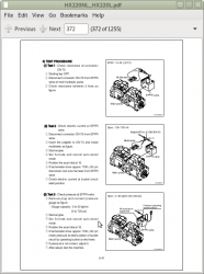
Hyundai Construction Crawler Excavator HX220L, HX220NL Repair Service Manual
Hyundai Construction Crawler Excavator HX220L, HX220NL Repair Service Manual
Complete service repair manual for Hyundai Construction Crawler Excavator HX220L, HX220NL, with all the shop information to maintain, diagnostic, repair, refurbish/rebuild like professional mechanics.
Hyundai Construction Crawler Excavator HX220L, HX220NL workshop service & repair manual includes:
* Numbered table of contents easy to use so that you can find the information you need fast.
* Detailed sub-steps expand on repair procedure information
* Numbered instructions guide you through every repair procedure step by step.
* Troubleshooting and electrical service procedures are combined with detailed wiring diagrams for ease of use.
* Notes, cautions and warnings throughout each chapter pinpoint critical information.
* Bold figure number help you quickly match illustrations with instructions.
* Detailed illustrations, drawings and photos guide you through every procedure.
* Enlarged inset helps you identify and examine parts in detail.
PRODUCT DETAILS:
Total Pages: 1,222 pages
File Format: PDF (Internal Links, Bookmarked, Table of Contents, Searchable, Printable, high quality)
Language: English
TABLE OF CONTENTS
SECTION 1 GENERAL
Group 1 Safety Hints - - 1-1
Group 2 Specifications - - 1-10
SECTION 2 STRUCTURE AND FUNCTION
Group 1 Pump Device - - 2-1
Group 2 Main Control Valve - - 2-20
Group 3 Swing Device - - 2-47
Group 4 Travel Device - - 2-58
Group 5 RCV Lever - - 2-72
Group 6 RCV Pedal - - 2-79
SECTION 3 HYDRAULIC SYSTEM
Group 1 Hydraulic Circuit - - 3-1
Group 2 Main Circuit - - 3-2
Group 3 Pilot Circuit - - 3-5
Group 4 Single Operation - - 3-14
Group 5 Combined Operation - - 3-24
SECTION 4 ELECTRICAL SYSTEM
Group 1 Component Location - - 4-1
Group 2 Electrical Circuit - - 4-3
Group 3 Electrical Component Specification - - 4-21
Group 4 Connectors - - 4-29
SECTION 5 MECHATRONICS SYSTEM
Group 1 Outline - - 5-1
Group 2 Mode selection System - - 5-3
Group 3 Automatic Deceleration System - - 5-6
Group 4 Power Boost System - - 5-7
Group 5 Travel Speed Control System - - 5-8
Group 6 Automatic Warming Up Function - - 5-9
Group 7 Engine Overheat Prevention Function - - 5-10
Group 8 Variable Power Control System - - 5-11
Group 9 Attachment Flow Control System - - 5-12
Group 10 Boom Floating Control System - - 5-13
Group 11 Intelligent Power Control System - - 5-14
Group 12 Anti-Restart System - - 5-16
Group 13 Self-Diagnostic System - - 5-17
Group 14 Engine Control System - - 5-54
Group 15 EPPR (Electro Proportional Pressure Reducing) Valve - - 5-55
Group 16 Monitoring System - - 5-60
Group 17 Fuel Warmer System - - 5-95
SECTION 6 TROUBLESHOOTING
Group 1 Before Troubleshooting - - 6-1
Group 2 Hydraulic and Mechanical System - - 6-4
Group 3 Electrical System - - 6-24
Group 4 Mechatronics System - - 6-40
SECTION 7 MAINTENANCE STANDARD
Group 1 Operational Performance Test - - 7-1
Group 2 Major Components - - 7-21
Group 3 Track and Work Equipment - - 7-29
SECTION 8 DISASSEMBLY AND ASSEMBLY
Group 1 Precaution - - 8-1
Group 2 Tightening Torque - - 8-4
Group 3 Pump Device - - 8-7
Group 4 Main Control Valve - - 8-30
Group 5 Swing Device - - 8-54
Group 6 Travel Device - - 8-84
Group 7 RCV Lever - - 8-116
Group 8 Turning Joint - - 8-130
Group 9 Boom, Arm and Bucket Cylinder - - 8-135
Group 10 Undercarriage - - 8-152
Group 11 Work Equipment - - 8-164
SECTION 9 COMPONENT MOUNTING TORQUE
Group 1 Introduction guide - - 9-1
Group 2 Engine system - - 9-2
Group 3 Electric system - - 9-4
Group 4 Hydraulic system - - 9-6
Group 5 Undercarriage - - 9-10
Group 6 Structure - - 9-11
Group 7 Work equipment - - 9-15


