
John Deere 644H Loader Operator's Manual (OMT195362)
John Deere 644H Loader Operator's Manual (OMT195362)
Complete Operator's Manual for John Deere 644H Loader, with all the shop information to maintain & operate.
omt195362 - 644h loader (s.n. 585561-) Operator's Manual.pdf
Total Pages: 430 pages
File Format: PDF (Internal Links, Bookmarked, Table of Contents, Searchable, Printable, high quality)
Language: English
omt195362 - 644h loader (s.n. 585561-)
Table of Contents
Foreword
Emission Control Statement
Technical Information Feedback Form
Section 1-1: Safety-Safety Features
Safety Features
Section 1-2: Safety-General Precautions
Recognize Safety Information
Follow Safety Instructions
Operate Only If Qualified
Wear Protective Equipment
Avoid Unauthorized Machine Modifications
Add Cab Guarding For Special Uses
Inspect Machine
Stay Clear Of Moving Parts
Avoid High-Pressure Fluids
Beware Of Exhaust Fumes
Prevent Fires
Prevent Battery Explosions
Handle Chemical Products Safely
Dispose of Waste Properly
Prepare for Emergencies
Section 1-3: Safety-Operating Precautions
Use Steps And Handholds Correctly
Start Only From Operator's Seat
Use And Maintain Seat Belt
Prevent Unintended Machine Movement
Avoid Work Site Hazards
Use Special Care When Operating Loader
Keep Riders Off Machine
Avoid Backover Accidents
Avoid Machine Tip Over
Operating on Slopes
Operating Or Traveling On Public Roads
Inspect and Maintain ROPS
Add And Operate Attachments Safely
Section 1-4: Safety-Maintenance Precautions
Park And Prepare For Service Safely
Service Cooling System Safely
Remove Paint Before Welding or Heating
Make Welding Repairs Safely
Drive Metal Pins Safely
Section 1-5: Safety-Safety Signs
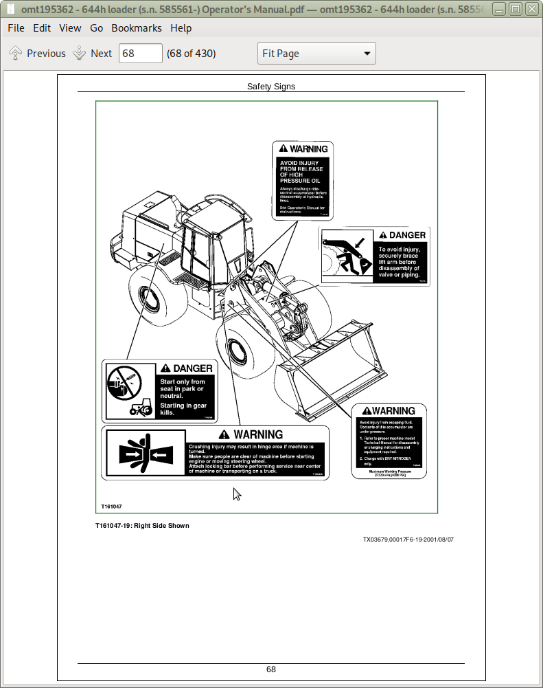
Safety Signs
Section 2-1: Operation-Operator’s Station
Levers
Pedals
Deluxe Monitor Panel
Deluxe Monitor Panel Functions
Console Switches and Accessories (Single Lever Design)
Console Switch and Accessory Functions (Single Lever Design)
Console Switches and Accessories (Two Lever Design)
Console Switch and Accessory Functions (Two Lever Design)
Monitor Display Unit
Monitor Display Unit-Normal Display
Monitor Display Unit-Accessory Menu-Clutch Cut-Off (A 01)
Monitor Display Unit-Accessory Menu-Quick Shift Mode (A 02)
Monitor Display Unit-Accessory Menu-Auto Mode to First (A 03)
Monitor Display Unit-Accessory Menu-Job Timer Mode (A 04)
Monitor Display Unit-Accessory Menu-Stop Watch Mode (A 05)
Monitor Display Unit-Accessory Menu-0.1 Hour Meter Mode (A 06)
Monitor Display Unit-Accessory Menu-Metric Units Mode (A 07)
Monitor Display Unit-User Diagnostics Menu-Service Codes (d01)
Monitor Display Unit-User Diagnostics Menu-Continuity Check (d 02)
Monitor Display Unit-User Diagnostics Menu-Battery Monitor (d 03)
Monitor Display Unit-User Diagnostics Menu-Engine Sensors (d 04)
Monitor Display Unit-User Diagnostics Menu-Transmission Sensors (d 05)
Monitor Display Unit-User Diagnostics Menu-Hydraulic Sensors (d 06)
Monitor Display Unit-User Diagnostics Menu-Fuel Sensor (d 07)
Monitor Display Unit-User Diagnostics Menu-(d 08)-Not Used
Monitor Display Unit-User Diagnostics Menu-Spin Control Mode (d 09)
Monitor Display Unit-User Diagnostics Menu-Machine I.D. Mode (d 10)
Horn Button
Turn Signals
Heating and Air Conditioning Controls
Heater Operation
Air Flow Knob
Adjusting Steering Wheel Tilt
Opening and Securing Side Door
Opening Side Window/Secondary Exit
Opening Rear Side Window
Adjusting Seat
Seat Belt
Section 2-2: Operation-Operating the Machine
Inspect Machine Daily Before Starting
Check Instruments Before Starting
Starting the Engine
Starting Fluid-If Equipped (Cold Weather Starting Aid)
Using Booster Batteries-24 Volt System
Engine Air Heater-If Equipped
Using Coolant Heater-If Equipped
Warm-Up
Cold Weather Warm-Up
Neutral Lock
Shifting the Transmission
Park Brake Switch
Boom and Bucket Control Lever-One Lever Design
Boom and Bucket Control Lever-Two Lever Design
Quick Shift Switch
Ride Control-If Equipped
Secondary Steering-If Equipped
Differential Lock Switch
Boom Height Kickout Adjustment
Return-to-Carry Kickout Adjustment
Return-To-Dig Adjustment
Fork Attachment
Arm Attachment
Parking the Machine
Loading Machine on a Trailer
Towing Procedure
Lifting the Machine
Section 3-1: Maintenance-Machine
Diesel Fuel
Low Sulfur Diesel Fuel Conditioner
Dieselscan Fuel Analysis
Handling and Storing Diesel Fuel
Alternative And Synthetic Lubricants
Diesel Engine Break-In Oil
Diesel Engine Oil
Transmission, Hydraulic System, Park Brake, and Differential Oil
Grease
Diesel Engine Coolant
Section 3-2: Maintenance-Periodic Maintenance
Service Your Machine at Specified Intervals
Check the Monitor Display Unit Regularly
Prepare Machine for Maintenance
Locking Machine Frame
Boom Lock
Opening Engine Side Shields and Service Doors
Opening Grille Door
Fuel Tank
Check Windshield Washer Fluid Level
Maintenance And Repair Record Keeping System
OILSCAN PLUS OILSCAN PLUS is a trademark of Deere & Company , COOLSCAN PLUSCOOLSCAN PLUS is a trademark of Deere & Company , and 3-Way Coolant Test Kit
Service Intervals
Required Parts
Section 3-3: Maintenance-As Required
Check Tire Pressure
Tire Pressures
Tighten Wheel Retainer Cap Screws
Clean or Replace Air Cleaner Elements
Check Air Inlet Cap
Inspect Serpentine Belt
Drain Fuel Tank Sediment
Drain Water Separator Sediment
Section 3-4: Maintenance-Every 10 Hours or Daily
Check Recovery Tank Coolant Level
Clean Air Cleaner Dust Unloader Valve
Check Engine Oil Level
Check Hydraulic Oil Level
Check Transmission Oil Level
Section 3-5: Maintenance-After 100 Hours
Change Engine Break-In Oil and Replace Filter
Change Transmission Oil
Replace Transmission Oil Filter
Section 3-6: Maintenance-Every 100 Hours
Grease Loader Linkage and Cylinder Pivots
Grease Front Steering Cylinder Pivots
Grease Oscillating Rear Axle and Rear Steering Cylinder Pivots
Check Cab Fresh Air Filter-If Equipped With Cab
Check Cab Recirculating Air Filter-If Equipped With Cab
Section 3-7: Maintenance-Every 250 Hours
Grease Front Driveline Sliding Joint
Check Receiver Dryer Moisture Indicator
Check Radiator Coolant Level
Change Engine Oil and Replace Filter
Section 3-8: Maintenance-Every 500 Hours
Grease Upper and Lower Drive Line Sliding Joints and U-Joints
Check Air Intake Hoses
Check Battery Electrolyte Level and Terminals
Clean Fuel Filter Strainer
Replace Final Fuel Filter
Replace Hydraulic System Return Filter
Grease Rear Oscillating Support Cover
Replace Hydraulic Reservoir Breather Filter
Replace Transmission Oil Filter
Check Park Brake Oil Level
Check Front and Rear Differential Oil Level
Section 3-9: Maintenance-Every 1000 Hours
Clean Engine Crankcase Vent Tube
Replace Air Cleaner Dust Unloader Valve
Replace Air Cleaner Elements
Check Coolant
Check Radiator Hoses
Change Transmission Oil
Grease Frame Hinge Pivots
Change Park Brake Oil
Section 3-10: Maintenance-Every 2000 Hours
Adjust Engine Valve Lash (Clearance)
Section 3-11: Maintenance-Every 3000 Hours
Change Hydraulic System Oil
Clean Hydraulic System Strainer
Change Front and Rear Differential Oil
Clean Axle Differential Recirculation Screen
Section 4-1: Miscellaneous-Machine
Draining the Cooling System
Filling the Cooling System
Replacing Engine Vibration Damper
Checking Fuel Tank Vent Hose
Adjusting Pilot Controller Tower
Bleeding Fuel System
Checking Fire Extinguisher-If Equipped
Precautions for Alternator and Regulator
Handling, Checking And Servicing Batteries Carefully
Replacing Batteries
Removing and Installing Batteries
Replacing Fuses
Fuse (Blade-Type) Color Codes
Replacing Halogen Bulbs
Engine Speeds
Checking Neutral Start System
Servicing Air Conditioning System-If Equipped
Welding on Machine
External Service Brake Inspection
Checking Ride Control Accumulator-If Equipped
Transmission Oil Cooler, Hydraulic Oil Cooler, Air-to-Air Aftercooler, and Radiator External Cleaning Procedure
Service Recommendations For STC® STC is a registered trademark of the Aeroquip Corporation. Fittings
Do Not Service Control Valves, Cylinders, Pumps or Motors
Hardware Torque Specifications
Keep ROPS Installed Properly
Metric Bolt and Cap Screw Torque Values
Unified Inch Bolt and Cap Screw Torque Values
Section 4-2: Miscellaneous-Operational Checkout
Operational Checkout
Section 4-3: Miscellaneous-Troubleshooting
Troubleshooting Procedure
Diagnostic Trouble Codes Quick Reference List
Engine
Transmission
Differential And Axle
Service Brake
Drive Line
Park Brake
Hydraulic System
Steering
Air Conditioning System
Heater System
Section 4-4: Miscellaneous-Storage
Prepare Machine For Storage
Section 4-5: Miscellaneous-Machine Numbers
Record Product Identification Number (PIN)
Record Engine Serial Number
Record Transmission Serial Number
Record Hydraulic Pump Serial Number
Record Axle Serial Number
Section 4-6: Miscellaneous-Specifications
644H Specifications
644H High Lift Specifications
Drain and Refill Capacities-644H
Section 4-7: Miscellaneous-Crime Prevention Tips
Help Prevent Crime
Record Identification Numbers
Keep Proof of Ownership
Park Indoors Out of Sight
When Parking Outdoors
Reduce Vandalism
Report Thefts Immediately
![]()