
John Deere PowerTech E 4.5L & 6.8L Diesel Engines Component Technical Manual (CTM502)
Component Technical Manual with Electrical Wiring Diagrams for John Deere PowerTech E 4.5L & 6.8L Diesel Engines, with all the shop information to maintain, diagnostic, repair, refurbish/rebuild like professional mechanics.
Component Technical Manual for John Deere PowerTech E 4.5L & 6.8L Diesel Engines workshop service & repair manual includes:
* Numbered table of contents easy to use so that you can find the information you need fast.
* Detailed sub-steps expand on repair procedure information
* Numbered instructions guide you through every repair procedure step by step.
* Troubleshooting and electrical service procedures are combined with detailed wiring diagrams for ease of use.
* Notes, cautions and warnings throughout each chapter pinpoint critical information.
* Bold figure number help you quickly match illustrations with instructions.
* Detailed illustrations, drawings and photos guide you through every procedure.
* Enlarged inset helps you identify and examine parts in detail.
ctm503 - Dizelski motor 4045-6068 - ECU Nivel 16 - (Edición mundial) Tehnični priročnik za komponente.pdf
ctm504 - Moteur diesel 4045-6068 — Contrôleur ECU de niveau 16 - (Édition globale) Manuel technique des composants.pdf
ctm505 - Dieselmotor 4045-6068 – ECU (Stufe 16) – (Weltweite Ausgabe) Technisches Komponentenhandbuch.pdf
ctm506 - Motore diesel 4045–6068 – Livello ECU 16 - Manuale tecnico dei componenti (edizione universale).pdf
ctm507 - Motor Diesel 4045–6068 — ECU Nível 16 - (Edição Mundial) Manual técnico de Componentes.pdf
ctm511 - Дизельные двигатели 4045, 6068 — Блок управления двигателем (ECU), уровень 16 — (Глобальная версия) Техническое руководство по компонентам.pdf
ctm513 - 4045-6068 柴油发动机 — 16 级 ECU - (世界通用机型 ) 维修手册.pdf
ctm517 - Silnik Diesla 4045–6068 – Poziom ECU 16 - (Wydanie ogólnoświatowe) Podręcznik techniczny komponentów.pdf
ctm608 - 4045-6068 Dizel Motor — Seviye 16 ECU (Dünya Çapında Sürüm) Bileşen Teknik Kılavuzu.pdf
CTM502 (09NOV12) (ENGLISH) - John Deere PowerTech E 4.5L & 6.8L Diesel Engines (Level 16 Electronic Fuel System with Denso HPCR) Component Technical Manual.pdf
CTM502 - John Deere Level 16 Electronic Fuel System with Denso HPCR Component Technical Manual.pdf
PRODUCT DETAILS:
Total Pages: 1,501 pages
File Format: PDF (Internal Links, Bookmarked, Table of Contents, Searchable, Printable, high quality)
Language: English
ctm502 - 4045-6068 Diesel Engine — Level 16 ECU -: (Worldwide Edition) Component Technical Manual - Table of Contents
Foreword
Trademarks
Section 01: General
Group 000: Safety
Avoid Heating Near Pressurized Fluid Lines
Avoid High-Pressure Fluids
Avoid Hot Exhaust
Avoid Static Electricity Risk When Refueling
Construct Dealer-Made Tools Safely
Decommissioning — Proper Recycling and Disposal of Fluids and Components
Follow Safety Instructions
Handle Agricultural Chemicals Safely
Handle Fluids Safely—Avoid Fires
Handling Batteries Safely
Illuminate Work Area Safely
Install All Guards
Live With Safety
Park Machine Safely
Practice Safe Maintenance
Precautions for Welding
Prepare for Emergencies
Prevent Acid Burns
Prevent Battery Explosions
Prevent Machine Runaway
Protect Against High Pressure Spray
Protect Against Noise
Recognize Safety Information
Remove Paint Before Welding or Heating
Replace Safety Signs
Service Cooling System Safely
Service Machines Safely
Stay Clear of Rotating Drivelines
Support Machine Properly
Understand Signal Words
Use Proper Lifting Equipment
Use Proper Tools
Use Steps and Handholds Correctly
Wait Before Opening High-Pressure Fuel System
Wear Protective Clothing
Work in Clean Area
Work In Ventilated Area
Group 001: Engine Identification
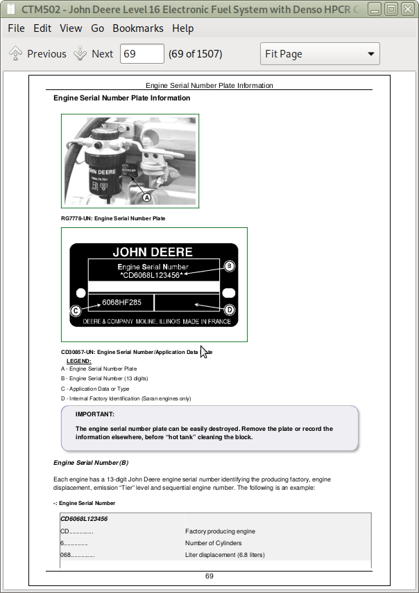
Engine Serial Number Plate Information
OEM Engine Option Code Label
Information Relative to Emissions Regulations
Emissions Control System Certification Label
Group 002: Fuels, Lubricants, and Coolant
Diesel Fuel
Diesel Fuel Additive Products
BioDiesel Fuel
Minimizing the Effect of Cold Weather on Diesel Engines
Handling and Storing Diesel Fuel
Lubricity of Diesel Fuel
Testing Diesel Fuel
Engine Oil and Filter Service Intervals
Diesel Engine Oil — Tier 3 and Stage III
Diesel Engine Break-In Oil — Non-Emissions Certified and Certified Tier 1, Tier 2, Tier 3, Stage I, Stage II, and Stage III
Oil Filters
Grease
Alternative and Synthetic Lubricants
Lubricant Storage
Mixing of Lubricants
Diesel Engine Coolant (engine with wet sleeve cylinder liners)
Supplemental Coolant Additives
Operating in Warm Temperature Climates
Additional Information About Diesel Engine Coolants and John Deere LIQUID COOLANT CONDITIONER
Diesel Engine Coolant
Testing Diesel Engine Coolant
Drain Intervals for Diesel Engine Coolant
Section 02: Repair and Adjustments
Group 090: Electronic Fuel System Repair and Adjustments
Fuel System - General Information
Relieve Fuel System Pressure
Fuel System Components
Replace Fuel Filter Element (Primary or Final)
Remove and Install Fuel Filter Base (Primary and Final)
Remove Fuel Transfer Pump
Install Fuel Transfer Pump
Remove and Install High-Pressure Fuel Pump
Remove and Install Suction Control Valve
Remove and Install High-Pressure Common Rail
Remove and Install Flow Dampers
Remove and Install Pressure Limiter
Remove and Install Fuel Injection Wire Harness Assembly
Injector Identification Tag Information
Remove Electronic Injector (EI)
Clean Electronic Injector (EI) Bore
Clean Electronic Injector (EI) Orifice
Clean Electronic Injector (EI) Body
Inspect Electronic Injector (EI) Body
Install Electronic Injector (EI)
Remove and Install Fuel Leak-Off Line
Clean Electronic injectors (In Engine)
Group 110: Electronic Engine Control Repair and Adjustment
Engine Control Unit (ECU) Maintenance
Welding
High Pressure Washing
Remove and Install Engine Control Unit (ECU) on Engine (Optional Equipment)
Remove and Install Adaptation Parts for Engine Control Unit (ECU) Mounted on Engine (Optional Equipment)
Remove and Install Engine Coolant Temperature (ECT) Sensor
Remove and Install Fuel Temperature Sensor
Remove and Install Manifold Air Temperature (MAT) Sensor
Remove and Install Oil Pressure Sensor
Remove and Install Fuel Rail Pressure Sensor
Remove and Install Fuel Transfer Pump Pressure Sensor
Remove and Install Crankshaft Position Sensor
Remove and Install Pump Position Sensor
Remove and Install Water-In-Fuel (WIF) Sensor
Install Wiring Harness for Engine Mount ECU
Install Wiring Harness for Remote ECU
Connectors
Connector Repair
Installation of Repair Wire Assembly (RWA)
Repair WEATHERPACK Connector
Repair Cinch FlexBox Connector
Repair Metri-Pack Connectors (Push Type)
Repair DT Series DEUTSCH Connectors
Repair HD Series DEUTSCH Connectors
Section 03: Theory Of Operation
Group 130: Electronic Fuel System Operation
About This Group
Fuel System Operation
Prefilter Operation
Mechanical Fuel Transfer Pump Operation
Electric Fuel Transfer Pump Operation
Final Fuel Filter Operation
Type 1 High Pressure Fuel Pump Operation
High Pressure Common Rail (HPCR) Operation
Electronic Injector (EI) Operation
Group 135: Air and Exhaust Operation
Air Intake and Exhaust System Operation
Air Cleaner Operation
Turbocharger Operation
How the Turbocharger Is Lubricated
Group 140: Electronic Control System Operation
About This Group
Electronic Control System Terminology
Electronic Control Unit (ECU) System Operation
Component Location Diagram 1
Component Location Diagram 2
Component Location Diagram 3
Component Location Diagram 4
Component Location Diagram 5
Component Location Diagram 6
Component Location Diagram 7
Component Location Diagram 8
Component Location Diagram 9
Component Location Diagram 10
Component Location Diagram 11
Component Location Diagram 12
Component Location Diagram 13
Component Location Diagram 14
Component Location Diagram 15
Component Location Diagram 16
Engine Control Unit (ECU)
Controller Area Network (CAN)
Pilot Injection Operation
Monitoring Engine Parameters
Measuring Temperature
Engine Control Unit (ECU) Temperature Sensor
Engine Coolant Temperature (ECT) Sensor
Fuel Temperature Sensor
Intake Manifold Air Temperature (MAT)
Turbo Turbine Inlet Temperature
Measuring Pressure
Barometric Air Pressure (BAP) Sensor
Fuel Rail Pressure Sensor
Fuel Transfer Pump Pressure Sensor
Manifold Air Pressure (MAP) Sensor
Oil Pressure Sensor
Dual Fuel Rail Pressure Sensor (Redundant ECU Applications)
Measuring Speed
Crank Position Sensor
Pump Position Sensor
Throttle Descriptions
CAN Throttle
Pulse-Width-Modulated (PWM) Throttle
Analog Throttle
Digital Multi-State Throttle
Dual-State Throttle
Tri-State Throttle
Ramp Throttle
Throttle Adjustments
Throttle Offsets
Self-Calibration
Combination Throttle
Marine Throttle
Engine Derate and Shutdown Protection
Electronic Injector (EI) Wiring Harness Connector
Intake Air Heater Operation
Torque Curve Selection
Governor Droop Mode Selection
Suction Control Valve
Water in Fuel (WIF) Sensor
Cruise Control Operation
Power Supply #1
Power Supply #2
Power Supply #3
Section 04: Diagnostics
Group 150: Observable Diagnostics and Tests
About This Group
E1 - Engine Cranks/Won't Start
E2 - Engine Misfires/Runs Irregularly
E3 - Engine Does Not Develop Full Power
E4 - Engine Emits Excessive White Exhaust
E5 - Engine Emits Excessive Black or Gray Exhaust
E6 - Engine Will Not Crank
E7 - Engine Idles Poorly
E8 - Abnormal Engine Noise
E9 - Primary Analog Throttle Does Not Respond
E10 - Secondary Analog Throttle Does Not Respond
F1 - Low-Pressure Fuel Supply System Test
F2 - High-Pressure Fuel Supply System Test
F3 - Excessive Fuel Consumption
F4 - Fuel in Oil
F5 - Excessive Fuel Filter Replacement
D1 - ECU Does Not Communicate with Service ADVISOR
D2 - ECU Does Not Communicate with Diagnostic Gauge or Gauge Displays CAN Bus Error
D5 - ECU Does Not Program With Service ADVISOR
A1 - Intake Air Heater Check
Bleed the Fuel System
Charge Air Cooler Test
Charge Air System
Check and Adjust High-Pressure Fuel Pump Static Timing
Check Engine Oil Pressure
Check for Restricted Fuel Leak-off Line
Check Fuel Supply Quality
Cylinder Leak-Down Test
Cooling System Test
EGR Cooler Test
Engine Coolant Temperature Below Normal
Excessive Engine Crankcase Pressure (Blow-By) Test
Test for Air in Fuel
Thermostat — Testing
Group 160: Trouble Code Diagnostics and Tests
About This Group
Change Fan Speed Table
Communication Error Test Instructions
Connecting to Service ADVISOR
Control Unit Information and Overview Test
Cylinder Cutout Test Instructions
Cylinder Electronic Compression Test Instructions
Cylinder Misfire Test Instructions
Diagnostic Gauge Active DTC Viewing Instructions
Diagnostic Gauge Data Parameters Viewing Instructions
Diagnostic Gauge Stored DTC Clearing Instructions
Diagnostic Gauge Stored DTC Viewing Instructions
Diagnostic Test Box — Using
Diagnostic Trouble Code Designations
Diagnostic Trouble Code List
Digital Multimeter — Using
Electrical Circuit Concepts
Electrical Noise — Possible Causes
Electronic Injector — Calibration Information
Engine Hours — Updating Instructions
Failure Mode Indicator Designations
Fuel Rail Cap and Plug Kit
Harness Diagnostic Mode Test
Interactive Tests and Calibration Results — Printing, Exporting, or Saving Instruction
Intermittent DTC Diagnostics
Internal Data Monitor — Instructions
Keep Electronic Control Unit Connectors Clean
Load Profile Information Test — Instructions
Engine Control Unit (ECU) — Level Identification
Engine Control Unit (ECU) — Donating this Engine’s ECU to be Used Elsewhere
Engine Control Unit (ECU) — Replacing Current ECU with Another ECU
Engine Control Unit (ECU) — Replacing Current ECU with Another ECU — Cannot Communicate with Current ECU
Engine Control Unit (ECU) — Reprogramming Current ECU
Engine Control Unit (ECU) — Reprogramming Instructions
Problem Not Found Procedure
Service Advisor Data Parameter Description
Short to Voltage Procedure
Snapshot Instructions
Software and Hardware Verification
Terminal Test
Trim Options Information
Verification Procedure
Wiggle Test
000028.03 - Digital Throttle Signal Out of Range High
000028.04 - Digital Throttle Signal Out of Range Low
000028.14 - Digital Throttle Inhibited
000029.03 - Secondary Analog Throttle Signal Out of Range High
000029.04 - Secondary Analog Throttle Signal Out of Range Low
000029.14 - Secondary Analog Throttle Inhibited
000084.31 - ECU Calculated Vehicle Speed and CAN Vehicle Speed Mismatch
000091.03 - Primary Analog Throttle Signal Out of Range High
000091.04 - Primary Analog Throttle Signal Out of Range Low
000091.09 - Primary Analog Throttle Signal Erratic
000091.14 - Primary Analog Throttle Inhibited
000094.03 - Low-Pressure Fuel Signal Out of Range High
000094.04 - Low-Pressure Fuel Signal Out of Range Low
000094.17 - Low Pressure Fuel Signal Slightly Low
000094.18 - Low-Pressure Fuel Signal Moderately Low
000097.03 - Water-In-Fuel Signal Out of Range High
000097.04 - Water-In-Fuel Signal Out of Range Low
000097.16 - Water-In-Fuel Detected
000100.01 - Engine Oil Pressure Signal Extremely Low
000100.04 - Engine Oil Pressure Signal Out of Range Low
000100.18 - Engine Oil Pressure Signal Moderately Low
000100.31 - Engine Oil Pressure Detected with Engine Stopped
000105.00 - Manifold Air Temperature Signal Extremely High
000105.03 - Manifold Air Temperature Signal Out of Range High
000105.04 - Manifold Air Temperature Signal Out of Range Low
000105.15 - Manifold Air Temperature Signal Slightly High
000105.16 - Manifold Air Temperature Signal Moderately High
000107.00 - Air Filter Restriction Switch Activated
000107.31 - Air Filter Restriction Switch Activated
000108.02 - Barometric Air Pressure Signal Invalid
000110.00 - Coolant Temperature Signal Extremely High
000110.03 - Coolant Temperature Signal Out of Range High
000110.04 - Coolant Temperature Signal Out of Range Low
000110.15 - Coolant Temperature Signal Slightly High
000110.16 - Coolant Temperature Signal Moderately High
000110.17 - Engine Coolant Temperature Signal Slightly Low
000111.01 - Coolant Level Extremely Low
000157.03 - Fuel Rail Pressure Signal Out of Range High
000157.04 - Fuel Rail Pressure Signal Out of Range Low
000157.10 - Fuel Rail Pressure Loss Detected
000157.17 - Fuel Rail Pressure Not Developed
000158.17 - ECU Power Down Error
000160.02 - Vehicle Speed Signal Invalid
000171.03 - Ambient Air Temperature Out of Range High
000171.04 - Ambient Air Temperature Out of Range Low
000174.00 - Fuel Temperature Signal Extremely High
000174.03 - Fuel Temperature Signal Out of Range High
000174.04 - Fuel Temperature Signal Out of Range Low
000174.16 - Fuel Temperature Signal Moderately High
000189.00 - Engine Speed Derate Condition Exists
000190.00 - Engine Speed Extremely High
000190.16 - Engine Speed Moderately High
000237.02 - VIN Security Data Invalid
000237.13 - VIN Option Code Security Data Conflict
000237.31 - VIN Security Data Missing
000569.03 - Rear Axle Differential Lock Signal Out of Range High
000569.04 - Rear Axle Differential Lock Signal Out of Range Low
000611.03 - Injector Shorted to Voltage Source
000611.04 - Injector Shorted to Ground
000627.01 - All Injector Circuits Have High Resistance
000627.18 - Injector Power Supply Voltage Out of Range Low
000629.12 - ECU EEPROM Error
000629.13 - ECU Boot Block Error
000636.02 - Camshaft Position Signal Invalid
000636.05 - Camshaft Position Circuit Has High Resistance
000636.06 - Camshaft Position Circuit Has Low Resistance
000636.08 - Camshaft Position Signal Missing
000636.10 - Camshaft Position Signal Rate of Change Abnormal
000637.02 - Crankshaft Position Signal Invalid
000637.05 - Crankshaft Position Circuit Has High Resistance
000637.06 - Crankshaft Position Circuit Has Low Resistance
000637.07 - Crankshaft and Camshaft Position Signals Out of Sync
000637.08 - Crankshaft Position Signal Missing
000637.10 - Crankshaft Position Signal Rate of Change Abnormal
000640.31 - External Derate Commanded
000647.05 - Engine Fan Drive Circuit Has High Resistance
000647.31 - Engine Fan Drive Manual Purge Switch Active Too Long
000651.02 - Injector #1 Part Number Invalid
000651.05 - Injector #1 Circuit Has High Resistance
000651.06 - Injector #1 Circuit Has Low Resistance
000651.13 - Injector #1 Calibration Fault
000652.02 - Injector #2 Part Number Invalid
000652.05 - Injector #2 Circuit Has High Resistance
000652.06 - Injector #2 Circuit Has Low Resistance
000652.13 - Injector #2 Calibration Fault
000653.02 - Injector #3 Part Number Invalid
000653.05 - Injector #3 Circuit Has High Resistance
000653.06 - Injector #3 Circuit Has Low Resistance
000653.13 - Injector #3 Calibration Fault
000654.02 - Injector #4 Part Number Invalid
000654.05 - Injector #4 Circuit Has High Resistance
000654.06 - Injector #4 Circuit Has Low Resistance
000654.13 - Injector #4 Calibration Fault
000655.02 - Injector #5 Part Number Invalid
000655.05 - Injector #5 Circuit Has High Resistance
000655.06 - Injector #5 Circuit Has Low Resistance
000655.13 - Injector #5 Calibration Fault
000656.02 - Injector #6 Part # Data Invalid
000656.05 - Injector #6 Circuit Has High Resistance
000656.06 - Injector #6 Circuit Has Low Resistance
000656.13 - Injector #6 Calibration Fault
000676.03 - Cold Start Aid Signal Received When Not Expected
000676.05 - Cold Start Aid Circuit Has High Resistance
000898.09 - Engine Speed CAN Message Invalid
000970.31 - External Shutdown Switch Activated
000970.31 - External Shutdown Switch Activated
000971.31 - External Derate Switch Activated
001069.31 - Tire Size Invalid
001075.05 - Low Pressure Fuel Pump Circuit Has High Resistance
001075.06 - Low Pressure Fuel Pump Circuit Has Low Resistance
001109.31 - Approaching Engine Protection Shutdown
001110.31 - Engine Protection Shutdown Active
001136.00 - ECU Temperature Signal Extremely High
001136.02 - ECU Temperature Signal Invalid
001136.16 - ECU Temperature Signal Moderately High
001321.05 - Starter Solenoid Lockout Relay Drive Circuit Has High Resistance
001321.06 - Starter Solenoid Lockout Relay Drive Circuit Has Low Resistance
001321.30 - Starter Solenoid Lockout Relay Drive Circuit Fault
001347.03 - Suction Control Valve Signal Out of Range High
001347.05 - Suction Control Valve Circuit Has High Resistance
001347.07 - Fuel Rail Pressure Actual to Desired Mismatch
001349.02 - Fuel Rail Pressure Signals Mismatch
001349.03 - Redundant Fuel Rail Pressure Signal Out of Range High
001349.04 - Redundant Fuel Rail Pressure Signal Out of Range Low
001569.31 - Engine in Power Derate Condition
001638.09 - Hydraulic Oil Temperature Erratic
001639.01 - Fan Speed Signal Extremely Low
001639.16 - Fan Speed Signal Moderately High
002000.13 - Incorrect ECU for Application
002003.09 - No CAN Message Received From Source Address 3
002004.09 - No CAN Message Received From Source Address 4
002023.09 - No CAN Message From Source Address 23
002033.09 - No CAN Message Received From Source Address 33
002033.14 - Incorrect CAN Message Received From Source Address 33
002033.19 - Synchronizing Problem with Source Address 33
002057.09 - No CAN Message Received From Source Address 57
002071.09 - No CAN Message From Source Address 71
003509.03 - Sensor Supply #1 Voltage Out of Range High
003509.04 - Sensor Supply #1 Voltage Out of Range Low
003510.03 - Sensor Supply #2 Voltage Out of Range High
003510.04 - Sensor Supply #2 Voltage Out of Range Low
003511.03 - Sensor Supply #3 Voltage Out of Range High
003511.04 - Sensor Supply #3 Voltage Out of Range Low
523792.04 - EPGDS LTC Pump Signal Out of Range Low
524099.11 - EPGDS LTC Pump Blockage
524037.02 - MFWD Switch Circuit Fault
524223.03 - Rear Axle Differential Lock Circuit Fault
524225.31 - Engine Start Protection Bypass Detected
524235.03 - MFWD Solenoid Signal Out of Range High
524235.04 - MFWD Solenoid Signal Out of Range Low
Section 05: Tools and Other Materials
Group 170: Special Tools
75240
D05104ST
D17030BR
DFRG11
J-35616-20
JDE83
JDG145
JDG359
JDG360
JDG361
JDG362
JDG363
JDG364
JDG776
JDG777
JDG782A
JDG783
JDG785
JDG820
JDG839
JDG865
JDG1560
JDG1571
JDG1652A
JDG1725
JDG1727
JDG1744
JDG1869
JDG10234
JDG10244
JDG10273
JDG10273P1
JDG10407
JDG10408
JDG10415
JDG10416
JDG10446
JDG10447
JDG10452
JDG10453
JDG10456
JDG10457
JDG10460
JDG10461
JDG10466
JDG10467
JDG10539A
JDG10576
JDG10760
JDG10854
JDG11072
JDG11100A
JDG11233
JDG11263
JDG11264
JDG11269
JDG11409
JT03513C
JT05412
JT05470
JT05536
JT07253
JT07306
Group 180: Lubricants, Sealants, and Other Materials
Other Materials (Consumables)
Section 06: Specifications
Group 200: Repair Specifications
Unified Inch Bolt and Cap Screw Torque Values
Metric Bolt and Cap Screw Torque Values
Electronic Fuel System Repair and Adjustment Specifications
Electronic Engine Control Repair and Adjustment Specifications
Group 210: Diagnostic Specifications
Fuel System Diagnostic Specifications
Application Specifications
OEM Engines - Derate Specifications
OEM Engines - Air Heater Specifications
4.5L 12V ECU Wiring Diagram 1
4.5L 12V ECU Wiring Diagram 2
4.5L 12V ECU Wiring Diagram 3
4.5L 12V ECU Wiring Diagram 4
4.5L 12V ECU Wiring Diagram 5
4.5L 12V ECU Wiring Diagram 6
4.5L 12V ECU Wiring Diagram 7
4.5L 24V ECU Wiring Diagram 1
4.5L 24V ECU Wiring Diagram 2
4.5L 24V ECU Wiring Diagram 3
4.5L 24V ECU Wiring Diagram 4
4.5L 24V ECU Wiring Diagram 5
4.5L 24V ECU Wiring Diagram 6
4.5L 24V ECU Wiring Diagram 7
6.8L 12V ECU Wiring Diagram 1
6.8L 12V ECU Wiring Diagram 2
6.8L 12V ECU Wiring Diagram 3
6.8L 12V ECU Wiring Diagram 4
6.8L 12V ECU Wiring Diagram 5
6.8L 12V ECU Wiring Diagram 6
6.8L 12V ECU Wiring Diagram 7
6.8L 24V ECU Wiring Diagram 1
6.8L 24V ECU Wiring Diagram 2
6.8L 24V ECU Wiring Diagram 3
6.8L 24V ECU Wiring Diagram 4
6.8L 24V ECU Wiring Diagram 5
6.8L 24V ECU Wiring Diagram 6
6.8L 24V ECU Wiring Diagram 7
OEM Instrument Panel / Engine Start Components Electrical Wiring Diagram
OEM Instrument Panel / Engine Start Components Electrical Wiring Diagram - Continued
4.5L Wire Splice Location Diagrams
6.8L Wire Splice Location Diagrams
Oil Temperature Switch Option
Redundant ECU Option 4.5L Wiring Diagrams
Redundant ECU Option 6.8L Wiring Diagrams
Redundant ECU Option Wire Splice Location Diagrams
![]()