
John Deere Alternators & Starter Motors Component Technical Manual (CTM77)
Complete service technical manual with electrical wiring diagrams for John Deere Alternators & Starter Motors, with all the workshop information to maintain, diagnose, repair, and service like professional mechanics.
John Deere Alternators & Starter Motors workshop CTM technical service manual includes:
* Numbered table of contents easy to use so that you can find the information you need fast.
* Detailed sub-steps expand on repair procedure information
* Numbered instructions guide you through every repair procedure step by step.
* Troubleshooting and electrical service procedures are combined with detailed wiring diagrams for ease of use.
* Notes, cautions and warnings throughout each chapter pinpoint critical information.
* Bold figure number help you quickly match illustrations with instructions.
* Detailed illustrations, drawings and photos guide you through every procedure.
* Enlarged inset helps you identify and examine parts in detail.
CTM77 - John Deere Alternators & Starter Motors Component Technical Manual.pdf
CTM77 (30OCT00) - John Deere Alternators & Starter Motors Component Technical Manual.epub
Total Pages: 811 pages
File Format: PDF (bookmarked, ToC, Searchable, Printable, high quality) & EPUB/MOBI/AZW for Kindle etc.
Language: English
Main Sections
Foreword
Introduction and Safety Information
Delco-Remy Alternators
Motorola Alternators
Niehoff Alternators
Denso Alternators
Bosch Alternators
Valeo Alternators
Magneton Alternators
Leece-Neville Alternators
Prestolite Alternators
Iskra Alternators
Delco-Remy Starter Motors
John Deere/Denso Starter Motors
Bosch Starter Motors
Iskra Starter Motors
Valeo Starter Motors
Magneton Starter Motors
Table of Contents - expanded view
Foreword
Introduction and Safety Information
Safety
Handle Fluids Safely—Avoid Fires
Prevent Battery Explosions
Prepare for Emergencies
Handling Batteries Safely
Wear Protective Clothing
Work in Clean Area
Service Machines Safely
Work In Ventilated Area
Illuminate Work Area Safely
Use Proper Lifting Equipment
Remove Paint Before Welding or Heating
Practice Safe Maintenance
Use Proper Tools
Dispose of Waste Properly
Prevent Machine Runaway
Live With Safety
General Information
Unified Inch Bolt and Screw Torque Values
Metric Bolt and Screw Torque Values
Electrical System Basic Information and Wiring Diagrams
Electrical Circuit Malfunctions
High Resistance Circuit
Open Circuit
Grounded Circuit
Shorted Circuit
Seven Step Electrical Test Procedure
Multimeter
Delco-Remy Alternators
Delco-Remy Alternator Theory of Operation
Delco-Remy (Delcotron) Alternator Operation
Delco-Remy (Delcotron) Regulator Operation
Delco-Remy (Delcotron) 10SI, 12SI and 15SI Alternator Repair
Essential Tools
Other Material
Delco-Remy (Delcotron) 10SI, 12SI, and 15SI Charging Circuit Repair Specifications
Delco-Remy (Delcotron) 10SI, 12SI, and 15SI Charging Circuit Test Specifications
Remove Pulley Nut
Separate Housing
Remove Front Bearing
Install Front Bearing
Remove and Install Rear Bearing
Test Rotor for Grounds
Test Rotor for Open Circuit
Test Rotor for Short Circuit
Repair Slip Rings
Inspect Stator
Test Stator for Grounds
Test Stator for Short Circuit
Test Brush Assembly for Grounds
Test Diode Trio
Test Rectifier Bridge
Regulator Test
Assemble the Alternator
Delco-Remy (Delcotron) 21SI Alternator Repair
Essential Tools
Delco-Remy (Delcotron) 21SI Charging Circuit Repair Specifications
Delco-Remy (Delcotron) 21SI Charging Circuit Test Specifications
Disassemble Delco-Remy 21SI Alternator
Disassemble Alternator
Slip Ring End Housing and Components
Drive End Frame and Components
Assemble Alternator
Slip Ring End Housing Assembly
Final Assembly
Motorola Alternators
Motorola Alternator Theory of Operation
Motorola Alternator Operation
Motorola Regulator Operation
Motorola 8E-Series Alternator Repair
Essential Tools
Motorola 8E-Series Charging Circuit Repair Specifications
Motorola 8E-Series Charging Circuit Test Specifications
General Information
Remove Alternator for Repair
Disassemble and Test Motorola 8E-Series (12-Volt, 65 Amp) Alternator
Assemble Motorola 8E-Series (12-Volt, 65 Amp) Alternator
Motorola HC-, MA-, MR-Series Alternator Repair
Essential Tools
Service Equipment and Tools
Motorola HC-, MA-, MR-Series Charging Circuit Repair Specifications
Motorola HC-, MA-, MR-Series Charging Circuit Test Specifications
Disassemble and Test Motorola HC-, MA-, MR-Series Alternator
Assemble Motorola HC-, MA-, MR-Series Alternator
Motorola A-, RA-, 8AR-Series Alternator Repair
Essential Tools
Motorola A-, RA-, 8AR-Series Charging Circuit Repair Specifications
Motorola A-, RA-, 8AR-Series Charging Circuit Test Specifications
Disassemble and Test Motorola A-, RA-, 8AR-Series Alternator
Assemble Motorola A-, RA-, 8AR-Series Alternator
Motorola SA-Series Alternator Repair
Essential Tools
Other Material
Motorola SA-Series Charging Circuit Repair Specifications
Motorola SA-Series Charging Circuit Test Specifications
Remove Alternator for Repair
Disassemble and Test Motorola SA-Series Alternator
Assemble Motorola SA-Series Alternator
Motorola TA-Series Alternator Repair
Essential Tools
Service Equipment and Tools
Motorola TA-Series Charging Circuit Repair Specifications
Motorola TA-Series Charging Circuit Test Specifications
Remove Alternator for Repair
Disassemble and Test Motorola TA-Series Alternator
Assemble Motorola TA-Series Alternator
Niehoff Alternators
Niehoff Alternator Theory of Operation
Starting the Niehoff Alternator
Niehoff Alternator Operation
Niehoff Alternator Load Dump Circuit
Niehoff 12-Volt, 110-Amp Alternator Repair
Essential Tools
Other Material
Niehoff 12-Volt Charging Circuit Repair Specifications
Niehoff 12-Volt Charging Circuit Test Specifications
Disassemble Niehoff 12-Volt, 110-Amp Alternator
Test Niehoff 12-Volt, 110-Amp Alternator Components
Assemble Niehoff 12-Volt, 110-Amp Alternator
Establish Magnetic Field
Niehoff 24-Volt, 50-Amp Alternator Repair
Essential Tools
Other Material
Niehoff 24-Volt Charging Circuit Repair Specifications
Niehoff 24-Volt Charging Circuit Test Specifications
Disassemble Niehoff 24-Volt, 50-Amp Alternator and Test Components
Assemble Niehoff 24-Volt, 50-Amp Alternator
Re-Establish Magnetic Field
Denso Alternators
Denso Alternator Theory of Operation
Denso Alternator Operation
Denso Regulator Operation
Denso Alternator with Add-On Regulator Repair
Essential Tools
Other Material
Denso Charging Circuit Repair Specifications (Alternators with Add-On Regulator)
Denso Charging Circuit Test Specifications (Alternators with Add-On Regulator)
Disassemble Denso Alternator with Add-On Regulator and Test Components
Separate Housing
Separate Housing and Remove Rear Bearing
Inspect Rear Bearing
Install Rear Bearing
Remove Stator, Rectifier Bridge and Brush Assembly
Test Brush Assembly
Install New Brushes
Inspect Stator
Test Stator for Grounds
Test Stator for Open or Short
Test Diodes in Rectifier Bridge
Test Diodes for Open or Short Circuit
Test Diode/Resistor Trio
Connect Stator Windings
Test Regulator
Assemble Rear Frame
Remove Pulley Nut
Remove and Inspect Front Bearing
Install Front Bearing Assembly
Test Rotor for Grounds
Test Rotor for Open or Shorted Circuits
Recondition Slip Rings
Install Rotor and Front Housing
Install Pulley Assembly
Install Regulator
Denso Alternator with Built-In Regulator Repair
Essential Tools
Other Material
Denso Charging Circuit Repair Specifications (Alternators with Built-In Regulator)
Denso Charging Circuit Test Specifications (Alternators with Built-In Regulator)
Disassemble and Test Denso Alternator with Built-In Regulator
Disassemble Alternator
Assemble Denso Alternator
Bosch Alternators
Bosch Alternator Theory of Operation
Function of Alternator
Bosch Alternator Repair
Essential Tools
Other Material
Bosch Charging Circuit Repair Specifications
Bosch Charging Circuit Test Specifications
Alternator, Section View
Alternator Removal
Removing Brush Holder with Regulator
Alternator Disassembly
Stator Removal
Diode Plate Removal
Alternator Exploded View
Testing Rotor for Short Circuit
Testing Rotor for Ground
Testing Slip Rings and Rotor Shaft for Radial Runout
Turning Down Slip Rings
Testing Stator Coil for Short Circuit
Testing Stator Coil for Grounds
Replacing Carbon Brushes
Replacing Ball Bearings
Checking Positive Diodes
Checking Negative Diodes
Testing Exciting Diodes
Diode Plate Installation
Soldering Stator Coils
Pressing Ball Bearing onto Rotor Shaft
Pressing Rotor into Drive End Frame
Assemble Alternator
Installing Brush Holder with Regulator
Fan and Belt Pulley Removal and Installation
Valeo Alternators
Valeo Alternator Theory of Operation
Valeo Alternator Operation
Valeo Regulator Operation
Valeo Alternator Repair
Essential Tools
Other Material
Valeo Charging Circuit Repair Specifications
Valeo Charging Circuit Test Specifications
Disassemble Alternator and Test Components
Assemble Alternator
Valeo A13N-Series Alternator Repair
Essential Tools
Valeo A13N-Series Repair Specifications
Valeo A13N-Series Test Specifications
Disassemble and Test Valeo A13N-Series Alternator
Assemble Valeo A13N-Series Alternator
Magneton Alternators
Magneton Alternator Theory of Operation
Operation of Alternator
Magneton Alternator Repair
Essential Tools
Magneton Charging Circuit Repair Specifications
Magneton Charging Circuit Test Specifications
Exploded View of Alternator
Identification
Troubleshooting
Disassembly of Alternator
Testing Brush/Regulator Assembly
Testing Rotor
Testing Stator/Rectifier Bridge Assembly
Rectifier Bridge Replacement
Reassembly of Alternator
Installation of Alternator
Leece-Neville Alternators
Leece-Neville Alternator Theory of Operation
Alternator Operation
Leece-Neville Alternator Repair
Essential Tools
Leece-Neville Repair Specifications
Leece-Neville Charging Circuit Test Specifications
Repair Alternator
Charging System Failure
Alternator Troubleshooting
Alternator Output Test
Diode Trio Test
Full Field Test
Adjust Regulator
Prestolite Alternators
Prestolite Alternator Theory of Operation
Alternator Operation
Prestolite Alternator Repair
Essential Tools
Prestolite Charging Circuit Test Specifications
Repair Alternator
Charging System Failure
Alternator Troubleshooting
Test Alternator
Iskra Alternators
Iskra Alternator Theory of Operation
Operation of Alternator
Iskra Alternator Repair
Essential Tools
Iskra Charging Circuit Repair Specifications
Iskra Charging Circuit Test Specifications
Exploded View of Alternator
Identification
Troubleshooting
Remove and Install Pulley
Testing Brush/Regulator Assembly
Install Brush/Regulator Assembly
Installation of Alternator
Delco-Remy Starter Motors
Starting Circuit Theory of Operation
General Information
Typical Starting Circuit Operation
Typical Starter Motor Operation
Delco-Remy 10/20/22/25/27/28MT Starter Motor Repair
Essential Tools
Service Equipment and Tools
Other Material
Delco-Remy 10MT, 20MT, 22MT, 25MT, 27MT, 28MT Starter Motor Repair Specifications
Delco-Remy 10MT, 20MT, 22MT, 25MT, 27MT, 28MT Starter Motor Test Specifications
Diagnosing Starter Motor Malfunctions
Delco-Remy Starter Motor Cutaway View—Series 10MT, 20MT, 22MT, 25MT, 27MT, 28MT
Check Operation of Motor Drive
Make Solenoid Pull-In Test
Make Solenoid Hold-In Test
Make Solenoid No-Load Test
Disassemble Starter Motor and Test Components
Clean Starter Motor Components
Inspect Armature
Make Short Circuit Test
Make Armature Ground Test
Make Open Circuit Test
Make Ground Circuit Test for Field Windings
Make Open Circuit Test for Field Windings
Remove Field Coils (If Necessary)
Install Field Windings
Disassemble Solenoid
Inspect and Clean Solenoid Parts
Assemble Solenoid
Remove Drive End Bushing and Wick
Install Drive End Bushing and Wick
Inspect Drive Motor ID
Inspect Center Bushing ID
Inspect Commutator End Frame Bushing
Assemble Starter Motor
Check Pinion Clearance
Make Solenoid No-Load Test
Delco-Remy 30MT, 35MT, 37MT Starter Motor Repair
Essential Tools
Service Equipment and Tools
Other Material
Delco-Remy 30MT, 35MT, and 37MT Starter Motor Repair Specifications
Delco-Remy 30MT, 35MT, and 37MT Starter Motor Test Specifications
Diagnosing Starter Motor Malfunctions
Delco-Remy Starter Motor Cutaway View—Series 30MT, 35MT, and 37MT
Test Starter Motor Before Disassembly
Make No-Load Test for Solenoid
Disassemble Delco-Remy Starter Motor (Series 35MT Illustrated)
Install New Bushings During Disassembly
Clean Starter Motor Components
Inspect Armature
Make Short Circuit Test
Make Armature Ground Test
Make Open Circuit Test
Make Ground Circuit Test for Field Windings
Make Open Circuit Test for Shunt Windings
Make Open Circuit Test for Field Windings
Remove Field Windings
Inspect Brushes
Test Brush Holder for Ground
Inspect Brush Springs
Inspect and Clean Solenoid
Assemble Solenoid
Inspect Plunger, Shift Lever, and Overrunning Clutch Assembly
Assemble Starter Motor
Check Armature End Play
Check for Proper Pinion Clearance
Make No-Load Test (After Assembly)
Delco-Remy 40MT, 41MT, 42MT, 50MT Starter Motor Repair
Essential Tools
Other Material
Delco-Remy 40MT, 41MT, 42MT, and 50MT Starter Motor Repair Specifications
Delco-Remy 40MT, 41MT, 42MT, and 50MT Starter Motor Test Specifications
Diagnosing Starter Motor Malfunctions
Delco-Remy Starter Motor Cutaway View—Series 40MT, 41MT, 42MT, and 50MT
Test Starter Motor Before Disassembly
Test Pull-In and Hold-In Windings
Make No-Load Test
Disassemble Delco-Remy Starter Motor ( Series 50MT Illustrated)
Make Ground Circuit Test for Field Windings
Make Open Circuit Test for Shunt Windings
Make Open Circuit Test for Field Windings
Remove Field Windings
Inspect Brushes
Test Brush Holder for Ground
Inspect Brush Springs
Install New Bushings—40MT, 41MT, and 42MT
Install New Bushings—50MT
Clean Starter Motor Components
Inspect Armature
Make Short Circuit Test
Make Armature Ground Test
Make Open Circuit Test
Inspect Solenoid Plunger and Shift Lever Assembly
Inspect Overrunning Clutch and Pinion
Inspect and Clean Solenoid
Assemble Solenoid
Assemble Starter Motor
Check for Proper Pinion Clearance
John Deere/Denso Starter Motors
Starting Circuit Theory of Operation
General Information
Typical Starting Circuit Operation
Starter Motor Operation (Conventional Type)
Starter Motor Operation (Gear Reduction Type)
Starter Motor Operation (Planetary Type)
John Deere/Denso Conventional Starter Motor Repair
Essential Tools
Service Equipment and Tools
Dealer Fabricated Tools
Other Material
John Deere/Denso Conventional Starter Motor Repair Specifications
John Deere/Denso Conventional Starter Motor Test Specifications
Test Starter Motor Before Disassembly
Make Solenoid Pull-In Test
Make Solenoid Return Test
Make No-Load Test
Diagnose No-Load Test
Disassemble Starter Motor
John Deere/Denso Conventional Starter Motor Exploded View
Install New Bushings/Needle Bearings
Clean Starter Motor Components
Inspect Armature
Make Short Circuit Test
Make Armature Ground Test
Make Open Circuit Test
Repair Armature
Inspect Overrunning Clutch and Pinion
Make Grounded Circuit Test for Field Windings
Make Open Circuit Test for Shunt Windings
Make Open Circuit Test for Field Windings
Remove Field Windings (If Necessary)
Install Field Windings
Inspect and Repair Brushes
Test Brush Holder for Grounds
Measure Brush Spring Tension
Disassemble Solenoid
Assemble Starter Motor
Install Solenoid
Make No-Load Test
John Deere/Denso Gear Reduction Starter Motor Repair
Essential Tools
Service Equipment and Tools
Other Material
John Deere/Denso Gear Reduction Starter Motor Repair Specifications
John Deere/Denso Gear Reduction Starter Motor Test Specifications
Bench Test Starter Motor
No-Load Test
John Deere/Denso Gear Reduction Starter Motor Exploded View
Disassemble Field Frame, Armature, and Brush Holder
Inspect and Repair Armature
Inspect Brushes and Brush Holder
Inspect Field Coils
Assemble Field Frame, Armature, and Brush Holder
Disassemble Gear Train and Overrunning Clutch
Assemble Gear Train and Overrunning Clutch
Disassemble, Inspect, and Repair Starter Solenoid
Assemble Solenoid Assembly
John Deere/Denso Planetary Starter Motor Repair
Essential Tools
Other Material
John Deere/Denso Planetary Starter Motor Repair Specifications
John Deere/Denso Planetary Starter Motor Test Specifications
Test Starter Motor Before Disassembly
Make Solenoid Pull-In Test
Make Solenoid Hold-In Test
Make Return Test
Make No-Load Test
Diagnose No-Load Test
Disassemble Starter Motor
John Deere/Denso Planetary Starter Motor Exploded View
Clean Starter Motor Components
Inspect and Repair Brushes
Test Brush Holder for Grounds
Measure Brush Spring Tension
Assemble Starter Motor
Install Solenoid
Make No-Load Test
Bosch Starter Motors
Starting Circuit Theory of Operation
General Information
Typical Starting Circuit Operation
Typical Starter Motor Operation
Bosch Conventional Starter Motor Repair
Essential Tools
Bosch Conventional Starter Motor Repair Specifications
Bosch Conventional Starter Motor Test Specifications
Make No-Load Test
Diagnosing Starter Motor Malfunctions
Bosch Conventional Starter Motor Cutaway View
Bosch Conventional Starter Motor Exploded View
Disassembly
Solenoid Switch—Removal
Carbon Brush Plate—Removal
Armature—Removal
Snap Ring—Removal
Cleaning Parts
Testing Armature for Grounds
Testing Armature for Short Circuit
Testing Armature for Open Circuit
Turning Commutator Down
Testing Commutator for Out-of-Roundness
Testing Field Winding for Grounded Circuit
Field Winding—Removal
Make Open Circuit Test for Field Windings
Lubrication of Starter Motor (Before and During Assembly)
Field Winding—Installation
Checking Carbon Brush Plate for Grounds
Testing Carbon Brushes
Replace Carbon Brushes
Engaging Lever—Installation
Checking Armature End Play and Torque
Installing Starter Motor
Bosch Planetary Gear Starter Motor Repair
Essential Tools
Bosch Planetary Gear Starter Motor Test Specifications
Make No-Load Test
Diagnosing Starter Motor Malfunctions
Bosch Planetary Gear Starter Motor Cutaway View
Disassemble Solenoid Switch
Test Solenoid Switch
Assemble Solenoid Switch
Iskra Starter Motors
Starting Circuit Theory of Operation
General Information
Typical Starting Circuit Operation
Starter Motor Operation
Iskra AZE/AZF/AZJ-Type Starter Motor Repair
Essential Tools
Dealer Fabricated Tools
Iskra AZF-Type Starter Motor Repair Specifications
Iskra AZJ-Type Starter Motor Repair Specifications
Iskra AZE, AZF-Type Starter Motor Test Specifications
Iskra AZJ-Type Starter Motor Test Specifications
Exploded View of Iskra Starter Motor (AZF-Type)
Exploded View of Iskra Starter Motor (AZJ-Type)
Troubleshooting
Identification
Disassembly of Starter Motor
Testing Solenoid Switch
Testing Brushes
Brush Replacement
Testing Armature
Testing Field Windings
Checking Engaging Lever
Checking Overrunning Clutch Pinion
Reassembly of Starter Motor
Iskra AZE-Type Starter Motor Repair
Essential Tools
Dealer Fabricated Tools
Iskra AZE-Type Starter Motor Repair Specifications
Iskra AZE-Type Starter Motor Test Specifications
Exploded View of AZE (Noseless)-Type Starter Motor
Troubleshooting
Identification
Removing Solenoid Switch
Testing Solenoid Switch
Installing Solenoid Switch
Valeo Starter Motors
Starting Circuit Theory of Operation
General Information
Typical Starting Circuit Operation
Typical Starter Motor Operation
Valeo Starter Motor Repair
Essential Tools
Valeo Starter Motor Repair Specifications
Valeo Starter Motor Test Specifications
Exploded View of Starter Motor
Disassembly of Starter Motor
Testing Solenoid Switch
Testing Brushes
Positive Brush Replacement
Testing Armature
Testing Field Winding
Checking Overrunning Clutch Pinion
Reassembly of Starter Motor
Magneton Starter Motors
Starting Circuit Theory of Operation
General Information
Typical Starting Circuit Operation
Starter Motor Operation
Magneton Starter Motor Repair
Essential Tools
Dealer Fabricated Tools
Magneton Starter Motor Repair Specifications
Magneton Starter Motor Test Specifications
Exploded View of Starter Motor
Identification
Troubleshooting
Disassembly of Starter Motor
Testing Solenoid Switch
Testing Brushes
Brush Holder Replacement
Testing Armature
Testing Field Winding
Checking Overrunning Clutch Pinion
Reassembly of Starter Motor
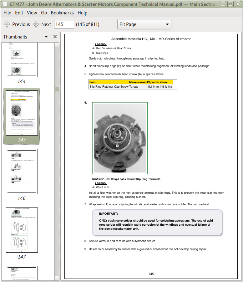
![]()