
Hitachi ZX470-5A, 470LC-5A, 490H-5A, 490LCH-5A, 530LCH-5A Excavators Repair Service Manuals
Complete service repair manual with electrical wiring diagrams for Hitachi ZX470-5A, 470LC-5A, 490H-5A, 490LCH-5A, 530LCH-5A Excavators, with all the shop information to maintain, diagnose, repair, and rebuild like professional mechanics.
Hitachi ZX470-5A, 470LC-5A, 490H-5A, 490LCH-5A, 530LCH-5A Excavators workshop service & repair manual includes:
* Numbered table of contents easy to use so that you can find the information you need fast.
* Detailed sub-steps expand on repair procedure information
* Numbered instructions guide you through every repair procedure step by step.
* Troubleshooting and electrical service procedures are combined with detailed wiring diagrams for ease of use.
* Notes, cautions and warnings throughout each chapter pinpoint critical information.
* Bold figure number help you quickly match illustrations with instructions.
* Detailed illustrations, drawings and photos guide you through every procedure.
* Enlarged inset helps you identify and examine parts in detail.
Total Pages: 1,472 pages
File Format: PDF (bookmarked, ToC, Searchable, Printable, high quality)
Language: English
MANUAL LIST:
TOJAE-EN-00 - Hitachi ZX470-5A, 470LC-5A, 490H-5A, 490LCH-5A, 530LCH-5A Hydraulic Excavator Technical Manual (Operational Principle).pdf
TTJAE-EN-00 (attach to) - Hitachi ZX470-5A, 470LC-5A, 490H-5A, 490LCH-5A, 530LCH-5A Hydraulic Excavator Electrical Circuit Diagram.pdf
TTJAE-EN-00 - Hitachi ZX470-5A, 470LC-5A, 490H-5A, 490LCH-5A, 530LCH-5A Hydraulic Excavator Technical Manual (Troubleshooting).pdf
WJAE-EN-00 - Hitachi ZX470-5A, 470LC-5A, 490H-5A, 490LCH-5A, 530LCH-5A Hydraulic Excavator Workshop Manual.pdf
TABLE OF CONTENTS
TECHNICAL MANUAL (Operational Principle)
SECTION 1 GENERAL
Group 1 Specification
CONTENTS
Group 2 Component Layout
Group 3 Component Specifications
SECTION 2 SYSTEM
Group 1 Controller
Group 2 Control System
Group 3 ECM System
Group 4 Hydraulic System
Group 5 Electrical System
SECTION 3 COMPONENT OPERATION
Group 1 Pump Device
Group 2 Swing Device
Group 3 Control Valve
Group 4 Pilot Valve
Group 5 Travel Device
Group 6 Signal Control Valve
Group 7 Others (Upperstructure)
Group 8 Others (Undercarriage)
MAIN SECTIONS
TOJAE-EN-00......1
INTRODUCTION......3
SYMBOL AND ABBREVIATION......5
SECTION AND GROUP CONTENTS......7
SECTION 1 GENERAL......9
Group 1 Specifications......11
Specifications ZX470-5A, 470LC-5A......11
Working Ranges ZX470-5A, 470LC-5A......12
Specifications ZX490H-5A, 490LCH-5A, 490LCH-5A (Bolt-joint Track)......13
Working Ranges ZX490H-5A, 490LCH-5A, 490LCH-5A (Bolt-joint Track)......14
Specifications ZX530LCH-5A......15
Working Ranges ZX530LCH-5A......16
Group 2 Component Layout......17
Main Component......17
Electrical System (Overview)......19
Electrical System (Rear Tray)......20
Electrical System (Switch Panel)......21
Electrical System (Utility Space)......22
Engine......24
Pump Device......25
Around Pump Device......26
Control Valve......27
Check Valve/Accumlator......28
Signal Control Valve......28
Swing Device......30
Travel Device......30
4-Spool Solenoid Valve Unit......31
Fan Valve (Option)......31
2-Spool Solenoid Valve Unit......31
Group 3 Component Specifications......33
Engine......33
Engine Accessories......37
Hydraulic Component......38
Electrical Component......42
SECTION 2 SYSTEM......45
Group 1 Controller......47
Outline......47
CAN Circuit......48
Group 2 Control System......51
Outline......51
Engine Control......54
Pump Control......76
Valve Control......100
Other Control......118
Group 3 ECM System......131
Outline......131
Fuel Injection Control......132
Fuel Injection Amount Correction Control......140
EGR Control......142
Preheating Control......144
Alarm Control......145
Fuel Bleeding Air Control......146
Group 4 Hydraulic System......147
Outline......147
Pilot Circuit......148
Main Circuit......160
Oil Cooler Fan Reverse Rotation Control Circuit (Option)......182
Group 5 Electrical System......183
Outline......183
Main Circuit......184
Electric Power Circuit (Key Switch: OFF)......186
CAN Circuit......188
Accessory Related Circuit (Key Switch: ACC)......190
Starting Circuit (Key Switch: START)......192
Charging Circuit (Key Switch: ON)......194
Surge Voltage Prevention Circuit......198
Pilot Shut-Off Circuit (Key Switch: ON)......200
Auto Shut-Down Circuit......202
Engine Stop Circuit......204
Monitor Circuit......207
Security Circuit......208
Radio Circuit......210
Air Conditioner Circuit......210
Accessory Circuit......213
Work Light Circuit......214
Wiper/Washer Circuit......218
Cab Light Circuit......220
SECTION 3 COMPONENT OPERATION......225
Group 1 Pump Device......227
Outline......227
Main Pump......228
Regulator......230
Pump Control Solenoid Valve......238
Fan Pump......240
Fan Pump Flow Rate Control......242
Pilot Pump......244
Pump Delivery Pressure Sensor......244
Pump Control Pressure Sensor......244
Group 2 Swing Device......245
Outline......245
Swing Reduction Gear......246
Swing Motor......247
Swing Parking Brake......248
Valve Unit......250
Group 3 Control Valve......253
Outline......253
Hydraulic Circuit......270
Flow Combiner Valve......276
Main Relief valve......278
Overload Relief Valve (with Make-Up Function)......282
Boom Overload Relief Valve (Low Pressure)......288
Regenerative Valve......290
Anti-Drift Valve......294
Flow Rate Control Valve......298
Boom Lower Meter-In Cut Valve......306
Bypass Shut-Out Valve......308
Auxiliary Flow Combiner Valve......312
Group 4 Pilot Valve......315
Outline......315
Operation (Front Attachment/Swing and Travel Pilot Valves)......317
Shockless Function (Only for Travel Pilot Valve)......325
Group 5 Travel Device......327
Outline......327
Travel Reduction Gear......328
Travel Motor......330
Parking Brake......332
Travel Brake Valve......334
Overload Relief Valve......338
Travel Mode Control......340
Group 6 Signal Control Valve......345
Outline......345
Pilot Port......346
Shuttle Valve......350
Shockless Valve......354
Pump 1 and Pump 2 Flow Rate Control Valves......358
Arm Flow Rate Control Valve Control Spool, Flow Combiner Valve Control Spool, Swing Parking Brake Release Spool......360
Group 7 Others (Upperstructure)......361
Pilot Shut-Off Solenoid Valve......361
Solenoid Valve......363
Fan Motor......366
Fan Valve (Option)......367
Pilot Relief Valve......373
Shockless Valve......374
Accumulator (Pilot Circuit)......376
Distribution Valve......377
Group 8 Others (Undercarriage)......381
Swing Bearing......381
Centerjoint......382
Track Adjuster......383
SERVICE MANUAL REVISION REQUEST FORM......387
TTJAE-EN-00 (attach to) - Hitachi ZX470-5A, 470LC-5A, 490H-5A, 490LCH-5A, 530LCH-5A Hydraulic Excavator Electrical Circuit Diagram......389
ELECTRICAL DIAGRAM......389
AIR CONDITIONER CIRCUIT DIAGRAM......390
CONNECTORS......391
CAB HARNESS......392
MAIN HARNESS......393
ENGINE HARNESS......394
PUMP HARNESS......395
CONTROL VALVE HARNESS......396
MONITOR HARNESS......397
KEY SWITCH HARNESS......398
OIL COOLER FAN REVERSE ROTATION SWITCH HARNESS......399
ENGINE STOP SWITCH HARNESS......400
PILOT SHUT-OFF SOLENOID VALVE HARNESS......401
GSM (MOBILE COMMUNICATION TERMINAL) HARNESS......402
SATELLITE COMMUNICATION HARNESS......403
AUTO LUBRICATION ON/OFF SWITCH HARNESS......404
CAMERA HARNESS......405
BOOM MODE SWITCH AND SEAT HEATER SWITCH HARNESS (OPTION)......406
WORK LIGHT (ON THE CAB ROOF) HARNESS 1 (OPTION)......407
WORK LIGHT (ON THE CAB ROOF) HARNESS 2 (OPTION)......408
HYDRAULIC CIRCUIT DIAGRAM......409
TTJAE-EN-00 - Hitachi ZX470-5A, 470LC-5A, 490H-5A, 490LCH-5A, 530LCH-5A Hydraulic Excavator Technical Manual (Troubleshooting)......410
TTJAE-EN-00......410
INTRODUCTION......412
SYMBOL AND ABBREVIATION......414
SAFETY......416
SECTION AND GROUP CONTENTS......456
SECTION 4......458
Group 1 Introduction......460
Operational Performance Tests......460
Preparation for Performance Tests......461
Group 2 Standard......462
Operational Performance Standard Table......462
Main Pump P-Q Diagram......466
Fan Pump P-Q Diagram......467
Sensor Activating Range......468
Monitor Indicating Values (MC)......469
Monitor Indicating Values (ECM)......475
Group 3 Engine Test......476
Engine Speed......476
Lubricant Consumption......479
Group 4 Machine Performance Test......480
Travel Speed......480
Track Revolution Speed......481
Mistrack Check......482
Travel Parking Leakage......483
Swing Speed......484
Swing Function Drift Check......485
Swing Motor Leakage......487
Maximum Swingable Slant Angle......489
Swing Bearing Play......491
Hydraulic Cylinder Cycle Time......493
Dig Function Drift Check......495
Control Lever Operating Force......498
Control Lever Stroke......499
Combined Operation of Boom Raise and Swing Function Check......500
Group 5 Component Test......502
Primary Pilot Pressure......502
Secondary Pilot Pressure......504
4-Spool Solenoid Valve Set Pressure......505
2-Spool Solenoid Valve Set Pressure......506
Main Pump Delivery Pressure......508
Fan Pump Delivery Pressure......509
Main Relief Set Pressure......510
Overload Relief Set Pressure......516
Main Pump Flow Rate Measurement......519
Fan Pump Flow Rate Measurement......521
Swing Motor Drainage......525
Travel Motor Drainage......527
Group 6 Adjustment......530
PUMP LEARNING......530
TORQUE ADJUSTMENT......531
CONNECTION......532
SECTION 5......536
Group 1 Diagnosing Procedure......538
Introduction......538
Diagnosis Procedure......539
Electrical System Inspection......542
Precautions for Inspection and Maintenance......543
Instructions for Disconnecting Connectors......545
Fuse Inspection......547
Fusible Link Inspection......550
Battery Voltage Check......551
Alternator Check......552
Continuity Check......553
Voltage and Current Measurement......555
Check by False Signal......562
Test Wire Harness......563
Group 2 Monitor......566
Outline......566
Operating Procedures of Service Menu......567
Setting Menu......604
Inspection of Engine Oil Level, Coolant Level, Hour Meter, and Fuel Gauge......606
Fuel Gauge and Coolant Temperature Gauge......607
Group 3 e-Service......608
Outline......608
List of Operation Data......609
Snapshot Data......613
Communication System......614
Group 4 Component Layout......616
Main Component......616
Electrical System (Overview)......618
Electrical System (Rear Tray)......619
Electrical System (Switch Panel)......620
Electrical System (Utility Space)......621
Engine......623
Pump Device......624
Around Pump Device......625
Control Valve......626
Check Valve/Accumlator......627
Signal Control Valve......627
Swing Device......629
Travel Device......629
4-Spool Solenoid Valve Unit......630
2-Spool Solenoid Valve Unit......630
Fan Valve (Option)......630
Layout of Control Valve......631
Pilot Port (Signal Control Valve)......647
Group 5 Troubleshooting A......652
Troubleshooting A (Base Machine Diagnosis......652
MC Fault Code List......654
ECM Fault Code List......673
Monitor Controller (Monitor) Fault Code List......678
Monitor Controller (Information) Fault Code List......679
Air Conditioner Controller Fault Code List......682
Communication Terminal Fault Code List......683
MC Fault Codes 11000 to 11002......684
MC Fault Code 11003......685
MC Fault Codes 11006, 11007,11009......688
Monitor Controller (Monitor) Fault Codes 13002, 13003, 13005......688
CAN0 Harness Check......689
MC Fault Codes 11008, 11010......692
Monitor Controller (Monitor) Fault Codes 13004, 13006, 13007......692
CAN1 Harness Check......693
MC Fault Code 11100......696
MC Fault Code 11101......697
MC Fault Codes 11200, 11202......698
MC Fault Codes 11301, 11302......699
MC Fault Code 11303......700
MC Fault Codes 11304, 11325......701
MC Fault Code 11405......702
MC Fault Code 11408......703
MC Fault Code 11412......704
MC Fault Code 11428......705
MC Fault Code 11802......706
MC Fault Code 11901......707
MC Fault Codes 11942, 11944......708
MC Fault Codes 11945......709
MC Fault Code 11948......710
MC Fault Code 11950......711
MC Fault Code 11951......712
MC Fault Code 11953......713
MC Fault Codes 11978, 11979......714
MC Fault Code 11982......715
MC Fault Codes 11985, 11986......716
MC Fault Code 11989......717
MC Fault Codes 11992, 11994......718
MC Fault Codes 11995, 11997......719
MC Fault Code 11998......720
MC Fault Codes 20062......721
Monitor Controller (Information) Fault Codes 13304, 13310......722
Monitor Controller (Information) Fault Code 13311......723
Monitor Controller (Information) Fault Codes 20100 to 20104, 20106......724
Monitor Controller (Information) Fault Codes 20107, 20109, 20110, 20114, 20146, 20149......725
Air Conditioner Controller Fault Codes 11 to 22......726
Air Conditioner Controller Fault Codes 43 to 92......727
Group 6 Troubleshooting B......728
Troubleshooting B (Machine Diagnosis by......728
Relationship between Machine Trouble Symptoms and Related Parts......730
Correlation Between Trouble Symptoms and Part Failures......756
Engine System Troubleshooting......774
All Actuator System Troubleshooting......781
Front Attachment System Troubleshooting......789
Swing System Troubleshooting......802
Travel System Troubleshooting......805
Other System Troubleshooting......809
Exchange Inspection......816
How to Lowering Boom When Emergency and When Engine Stops......819
Group 7 Air Conditioner......820
Outline......820
Functions of Main Parts......823
Troubleshooting......828
Air Conditioner Controller Fault Code List......829
Air Conditioner Controller Fault Codes 11 to 22......830
Air Conditioner Controller Fault Codes 43 to 92......831
Work after Replacing Components......853
Refill Compressor Oil......854
Charge Air Conditioner with Refrigerant......855
Hose and Pipe Tightening Torque......863
SERVICE MANUAL REVISION REQUEST FORM......866
The Attached Diagram List......866
WJAE-EN-00 - Hitachi ZX470-5A, 470LC-5A, 490H-5A, 490LCH-5A, 530LCH-5A Hydraulic Excavator Workshop Manual......868
WJAE-EN-00......868
INTRODUCTION......870
To The Reader......870
Additional References......870
Manual Composition......870
Page Number......870
Safety Alert Symbol and Headline Notations......871
Units Used......871
SYMBOL AND ABBREVIATION......872
SAFETY......874
Recognize Safety Information......874
Understand Signal Words......874
Follow Safety Instructions......875
Prepare for Emergencies......876
Wear Protective Clothing......876
Protect Against Noise......877
Inspect Machine......877
General Precautions for Cab......878
Use Handholds and Steps......879
Adjust the Operator's Seat......879
Ensure Safety Before Rising from or Leaving Operator’s Seat......880
Fasten Your Seat Belt......880
Move and Operate Machine Safely......881
Operate Only from Operator's Seat......881
Jump Starting......882
Keep Riders off Machine......882
Precautions for Operations......883
Investigate Job Site Beforehand......884
Install OPG Guard......885
Restriction of Attachment Installation......886
Provide Signals for Jobs Involving Multiple Machines......886
Confirm Direction of Machine to Be Driven......886
Drive Machine Safely......887
Avoid Injury from Rollaway Accidents......889
Avoid Injury from Back-Over and Swing Accidents......890
Keep Person Clear from Working Area......891
Never Position Bucket Over Anyone......891
Avoid Undercutting......892
Avoid Tipping......892
Never Undercut a High Bank......893
Dig with Caution......893
Operate with Caution......893
Avoid Power Lines......894
Precautions for Lightning......894
Object Handling......895
Protect Against Flying Debris......895
Park Machine Safely......896
Handle Fluids Safely−Avoid Fires......896
Transport Safely......897
Practice Safe Maintenance......898
Warn Others of Service Work......899
Support Machine Properly......899
Stay Clear of Moving Parts......900
Prevent Parts from Flying......900
Avoid Injury from Attachment Falling Accident......901
Prevent Burns......901
Replace Rubber Hoses Periodically......902
Avoid High-Pressure Fluids......902
Prevent Fires......903
Evacuating in Case of Fire......905
Beware of Exhaust Fumes......905
Precautions for Welding and Grinding......906
Avoid Heating Near Pressurized Fluid Lines......907
Avoid Applying Heat to Lines Containing Flammable Fluids......907
Precautions for Handling Accumulator and Gas Damper......907
Remove Paint Before Welding or Heating......908
Beware of Asbestos and Silicon Dust and Other Contamination......908
Prevent Battery Explosions......909
Service Air Conditioning System Safely......909
Handle Chemical Products Safely......910
Dispose of Waste Properly......910
Never Ride Attachment......911
Precautions for Communication Terminal......911
Precautions for Communication Terminal Equipment......912
Before Returning the Machine to the Customer......913
SECTION AND GROUP CONTENTS......914
SECTION 1 GENERAL......916
Group 1 Precautions for Disassembling and Assembling......918
Precautions for Disassembling and Assembling......918
Group 2 Tightening......924
Tightening Bolts and Nuts......924
Piping Joint......927
Group 3 Painting......934
Painting specification......934
Final painted color......934
Group 4 Bleeding Air......936
Bleeding Air from Hydraulic Oil Tank (Pressure Release)......936
Bleeding Air from Hydraulic System......937
Bleeding Air from Fuel System......938
Bleeding Air from Expansion Tank (Radiator) (Pressure Release)......940
Group 5 Pressure Release Procedure......942
Hydraulic Circuit Pressure Release Procedure......942
Group 6 Preparation......944
Preparation before Inspection and Maintenance......944
SECTION 2 MAINTENANCE STANDARD......948
Group 1 Upperstructure......950
Main Pump......950
Fan Pump......951
Swing Motor......952
Group 2 Undercarriage......954
Travel Motor......954
Sprocket......955
Center Joint......956
Front Idler......958
Upper Roller......960
Lower Roller......961
Track......962
Group 3 Front Attachment......966
Remove and Install Bushing......966
Pin and Bushing......968
Side Cutter......970
Point......970
Standard Dimensions for Arm and Bucket Connection......971
Standard Dimensions for Arm and Boom Connection......973
Cylinder......974
SECTION 3 UPPERSTRUCTURE......978
Group 1 Cab......980
Removal and Installation of Cab......980
Dimensions of Cab Glass (Standard Cab)......996
Dimensions of Cab Glass (H Cab)......1015
Group 2 Counterweight......1018
Removal and Installation of Counterweight......1018
Group 3 Main Frame......1022
Removal and Installation of Main Frame......1022
Group 4 Engine......1030
Removal and Installation of Engine......1030
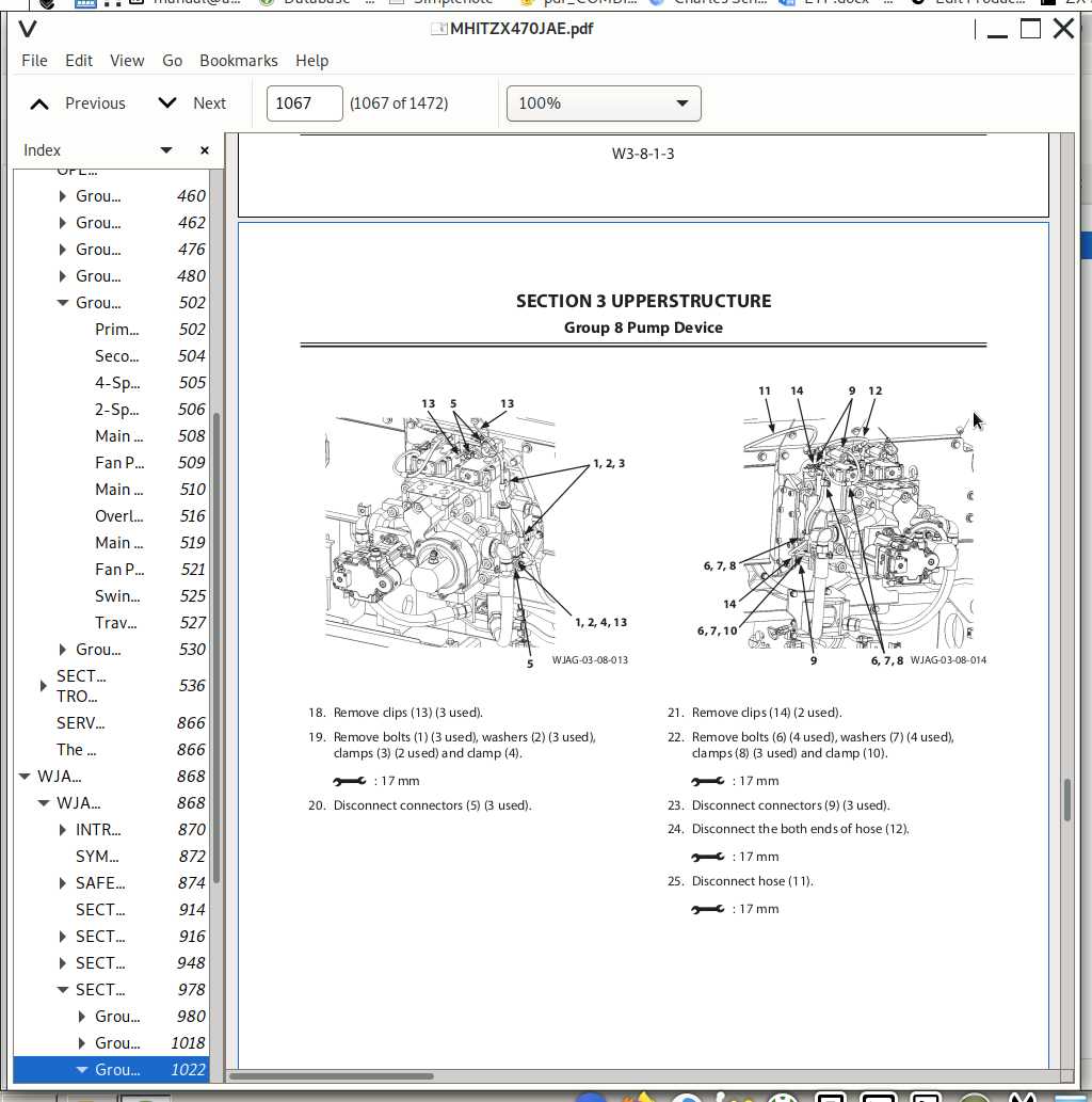
Group 8 Pump Device......1064
Removal and Installation of Pump Device......1064
Disassembly of Main Pump......1088
Assembly of Main Pump......1093
Disassembly of Regulator for Main Pump......1100
Assembly of Regulator for Main Pump......1102
Disassembly of Fan Pump......1106
Assembly of Fan Pump......1110
Structure of Pilot Pump......1114
Group 9 Control Valve......1116
Removal and Installation of Control Valve......1116
Disassembly and Assembly of Valve Unit......1130
Disassembly of Control Valve (4-Spool Side)......1136
Assembly of Control Valve (4-Spool Side)......1144
Disassembly of Control Valve (5-Spool Side)......1152
Assembly of Control Valve (5-Spool Side)......1159
Group 10 Swing Device......1166
Removal and Installation of Swing Device......1166
Disassembly of Swing Device......1170
Assembly of Swing Device......1176
Disassembly of Swing Motor......1182
Assembly of Swing Motor......1185
Group 11 Pilot Valve......1190
Removal and Installation of Pilot Valve (Left)......1190
Removal and Installation of Pilot Valve (Right)......1196
Removal and Installation of Travel Pilot Valve......1204
Disassembly of Pilot Valves (Right and Left)......1208
Assembly of Pilot Valves (Right and Left)......1211
Disassembly of Travel Pilot Valve......1214
Assembly of Travel Pilot Valve......1218
Group 12 Solenoid Valve......1224
Removal and Installation of Pilot Shut-Off Solenoid Valve......1224
Removal and Installation of 4-Spool Solenoid Valve Unit......1228
Removal and Installation of 2-Spool Solenoid Valve Unit......1232
Removal and Installation of Fan Pump Control Solenoid Valve......1236
Disassembly of Pilot Shut-Off Solenoid Valve......1240
Assembly of Pilot Shut-Off Solenoid Valve......1242
Structure of 4-Spool Solenoid Valve Unit......1244
Structure of 2-Spool Solenoid Valve Unit......1246
Structure of Fan Pump Solenoid Valve......1248
Group 13 Signal Control Valve......1250
Removal and Installation of Signal Control Valve......1250
Structure of Signal Control Valve......1256
Group 14 Shockless Valve......1260
Removal and Installation of Shockless Valve......1260
Structure of Shockless Valve......1262
Group 15 Fan Valve......1264
Removal and Installation of Fan Valve......1264
Structure of Fan Valve......1300
Group 16 Fan Motor......1302
Removal and Installation of Fan Motor......1302
Structure of Fan Motor......1310
SECTION 4 UNDERCARRIAGE......1314
Group 1 Swing Bearing......1316
Removal and Installation of Swing Bearing......1316
Disassembly of Swing Bearing......1320
Assembly of Swing Bearing......1323
Group 2 Travel Device......1326
Removal and Installation of Travel Device......1326
Disassembly of Travel Device......1330
Assembly of Travel Device......1337
Disassembly of Travel Motor......1346
Assembly of Travel Motor......1350
Disassembly of Brake Valve......1356
Assembly of Brake Valve......1359
Group 3 Center Joint......1364
Removal and Installation of Center Joint......1364
Disassembly of Center Joint......1368
Assembly of Center Joint......1370
Replacement of Body and Spindle......1373
Group 4 Track Adjuster......1374
Removal and Installation of Track Adjuster......1374
Disassembly of Track Adjuster......1376
Assembly of Track Adjuster......1381
Group 5 Front Idler......1386
Removal and Installation of Front Idler......1386
Disassembly of Front Idler......1388
Assembly of Front Idler......1391
Group 6 Upper and Lower Rollers......1396
Removal and Installation of Upper Roller......1396
Removal and Installation of Lower Roller......1400
Disassembly of Lower Roller......1404
Assembly of Lower Roller......1406
Group 7 Track......1412
Removal and Installation of Track......1412
SECTION 5 FRONT ATTACHMENT......1428
Group 1 Front Attachment......1430
Removal and Installation of Front Attachment......1430
Removal and Installation of Bushing......1438
Group 2 Cylinder......1440
Removal and Installation of Boom Cylinder......1440
Removal and Installation of Arm Cylinder......1444
Removal and Installation of Bucket Cylinder......1448
Disassembly of Boom Cylinder......1452
Assembly of Boom Cylinder......1455
Disassembly of Arm Cylinder......1458
Assembly of Arm Cylinder......1461
Disassembly of Bucket Cylinder......1464
Assembly of Bucket Cylinder......1467
SERVICE MANUAL REVISION REQUEST FORM......1472
Hitachi ZX470-5A, 470LC-5A, 490H-5A, 490LCH-5A, 530LCH-5A Excavators Repair Service Manuals
![]()