
John Deere 2.4L and 3.0L Diesel Engine Components Technical Manual (CTM301)
John Deere 2.4L and 3.0L Diesel Engine Components Technical Manual (CTM301)
John Deere 2.4L and 3.0L Diesel Engines Components Technical Manual (CTM301).pdf
Complete Components Technical Manual for John Deere 2.4L and 3.0L Diesel Engines, with all the shop information to maintain, diagnostic, repair, service like professional mechanics.
John Deere 2.4L and 3.0L Diesel Engines Component Technical Manual (CTM301) includes:
* Numbered table of contents easy to use so that you can find the information you need fast.
* Detailed sub-steps expand on repair procedure information
* Numbered instructions guide you through every repair procedure step by step.
* Troubleshooting and electrical service procedures are combined with detailed wiring diagrams for ease of use.
* Notes, cautions and warnings throughout each chapter pinpoint critical information.
* Bold figure number help you quickly match illustrations with instructions.
* Detailed illustrations, drawings and photos guide you through every procedure.
* Enlarged inset helps you identify and examine parts in detail.
Total Pages: 641 pages
File Format: PDF (bookmarked, ToC, Searchable, Printable, high quality)
Language: English
TABLE OF CONTENTS (Expanded View)
01 - GENERAL INFORMATION
00 - Safety
Avoid Heating Near Pressurized Fluid Lines
Avoid High-Pressure Fluids
Avoid Static Electricity Risk When Refueling
Construct Dealer-Made Tools Safely
Dispose of Waste Properly
DO NOT USE Starting Fluids
Handle Chemical Products Safely
Handle Fluids Safely—Avoid Fires
Handle Starting Fluid Safely
Handling Batteries Safely
Illuminate Work Area Safely
Live With Safety
Practice Safe Maintenance
Prepare for Emergencies
Prevent Acid Burns
Prevent Battery Explosions
Prevent Bypass Starting
Remove Paint Before Welding or Heating
Service Cooling System Safely
Service Machines Safely
Understand Signal Words
Use Proper Lifting Equipment
Use Proper Tools
Wear Protective Clothing
Work in Clean Area
Work In Ventilated Area
01 - Engine Identification Information
Engine Application Chart
Engine Model Designation
Engine Serial Number Plate
OEM Engine Option Code Label
Record Engine Serial Number
™ Medallion
02 - Fuels, Lubricants, and Coolant
Additional Information About Diesel Engine Coolants and John Deere LIQUID COOLANT CONDITIONER
Alternative and Synthetic Lubricants
Bio-Diesel Fuel
Diesel Engine Break-In Oil
Diesel Engine Coolant (engine with wet sleeve cylinder liners)
Diesel Engine Oil
Diesel Fuel Additive Products
Diesel Fuel
Diesel Fuel Storage
Disposing of Coolant
Extended Diesel Engine Oil Service Intervals
Filling Fuel Tank
Grease
Handling And Storing Bio-Diesel Fuel
Lubricant Storage
Lubricity of Diesel Fuel
Minimizing the Effect of Cold Weather on Diesel Engines
Mixing of Lubricants
Oil Filters
OILSCAN ® and COOLSCAN ™
Operating in Warm Temperature Climates
Supplemental Coolant Additives
Testing Diesel Engine Coolant
Testing Diesel Fuel
02 - REPAIR & ADJUSTMENTS
010 - Engine Rebuild
Clean Engine
Disconnect Turbocharger Oil Inlet Line
Engine Assembly Sequence
Engine Break-In Guidelines
Engine Disassembly Sequence
Engine Lifting Procedure
Engine Overhaul Guidelines
Engine Repair Stand
Engine Stand Safety Precautions
Install Adapters on Engine Repair Stand
Mount Engine on Repair Stand
Perform Engine Break-In
020 - Cylinder Head & Valve Repair & Adjustment
Check Cylinder Head Flatness
Clean and Inspect Valve Seats
Clean Valves
Cylinder Head - Exploded View
Cylinder Head — Thickness Measurement
Disassemble and Inspect Rocker Arm Assembly
Grind Valve Seats
Grind Valves
Head Gasket Inspection and Repair Sequence
Inspect and Clean Cylinder Head
Inspect and Clean Exhaust Manifold
Inspect and Measure Valves
Inspect and Measure Valve Springs
Inspect Cylinder Head Cap Screws
Inspect, Remove, and Install Glow Plugs and Wire Harness
Install Cylinder Head (4-Cylinder)
Install Cylinder Head (5-Cylinder)
Install Rocker Arm Assembly
Install Valves
Knurl Valve Guides
Measure Valve Recess in Cylinder Head
Preliminary Cylinder Head and Valve Checks
Remove and Install Rocker Arm Cover
Remove Cylinder Head
Remove Valve Assembly
030 - Cylinder Block, Liners, Pistons, and Connecting Rods
Assemble Piston and Connecting Rod
Check Engine Rotation for Excessive Tightness
Check Piston Ring Groove Wear
Clean Pistons
Complete Final Assembly
Connecting Rods—General Information
Deglaze Cylinder Bores
Determine Piston-to-Cylinder Bore Clearance
Disassemble Piston and Rod Assembly
Inspect and Clean Cylinder Block
Inspect and Measure Connecting Rod Bearings (Rod and Crankshaft in Engine)
Inspect and Measure Connecting Rod Bearings (Rods Removed from Engine)
Inspect and Measure Cylinder Bore
Inspect Piston Pins and Bushings
Inspect Rod and Cap
Install Piston and Connecting Rod Assembly
Install Piston Rings
Measure Camshaft Bushing Bores in Block
Measure Camshaft Follower Machined Bore
Measure Cylinder Block Main Bearing Bore
Measure Cylinder Block Top Deck Flatness
Measure Piston Height
Measure Piston Pin Bore
Measure Piston Protrusion - Locate TDC
Measure Piston Skirt
Measure Rod Center-to-Center Bores
Preliminary Cylinder Block, Pistons, and Rod Checks
Rebore Cylinder Bores
Remove, Inspect, and Install Piston Cooling Orifices
Remove Pistons and Connecting Rod Assembly
Torque-Turn Connecting Rod Cap Screws
Visually Inspect Pistons
040 - Crankshaft, Main Bearings, and Flywheel
Check Crankshaft End Play
Check Flywheel Face Flatness
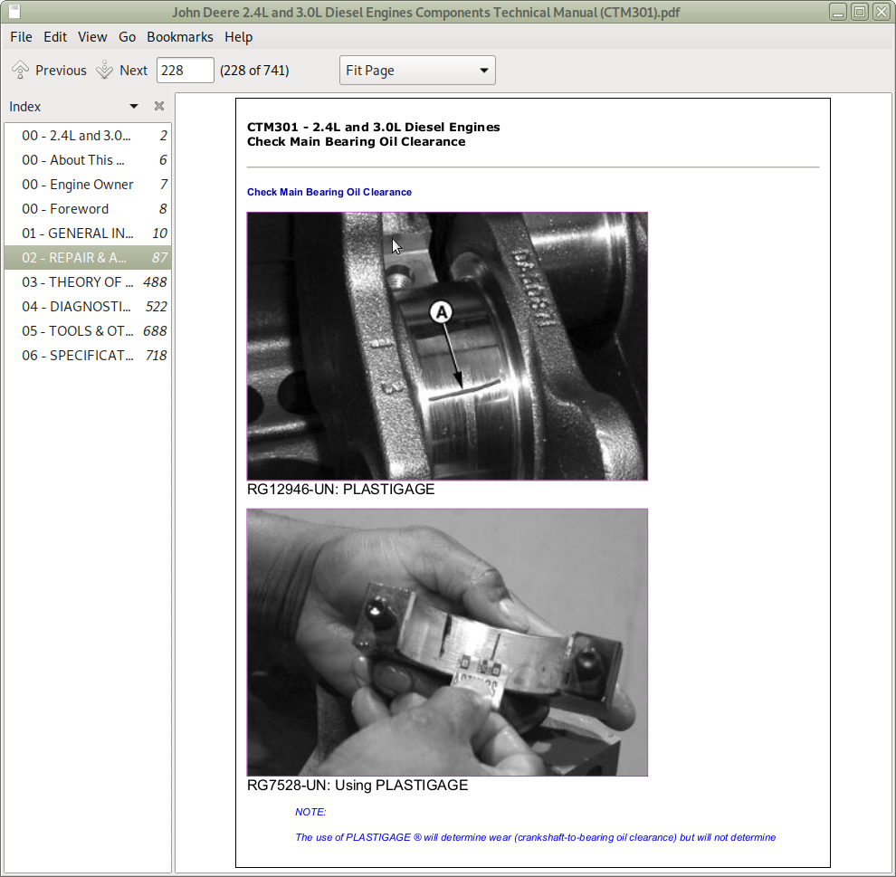
Check Main Bearing Oil Clearance
Check Pilot Bearing Bore Concentricity
Clean and Inspect Crankshaft Flange
Crankshaft and Main Bearing Failure Analysis
Crankshaft Grinding Guidelines
Crankshaft Grinding Specifications
Crankshaft Rear Oil Seal and Wear Sleeve Handling Precautions
Flywheel—Removal
Inspect Crankshaft
Inspect Flywheel
Inspect Pulley and Wear Sleeve
Inspect Vibration Damper (If Equipped)
Install Crankshaft Pulley _ Damper
Install Crankshaft Rear Oil Seal Housing
Install Crankshaft Rear Oil Seal
Install Flywheel Housing
Install Flywheel
Install Main Bearings, Thrust Washers and Crankshaft
Measure Assembled ID of Main Bearing Caps
Measure Crankshaft Journals and Main Bearing ID
Measure Main Thrust Journal Width and Thrust Washers
Remove Crankshaft Main Bearings
Remove Crankshaft
Remove Crankshaft Pulley _ Damper
Remove Crankshaft Rear Oil Seal and Housing
Remove Flywheel Housing
Replace Flywheel Ring Gear
Replace Front Crankshaft Oil Seal (Without Removing Timing Gear Cover)
050 - Camshaft, Balancing Shaft, and Timing Gear Train Repair & Adjustment
Clean and Inspect Timing Gear Cover
Inspect and Measure Balancer Shaft Bushings and Journals
Inspect and Measure Camshaft Bushing ID and Journal OD
Inspect Balancer Shaft Gears and Thrust Plates
Inspect Camshaft Followers
Inspect Camshaft
Install Balancer Bushings
Install Balancer Shafts (If Equipped)
Install Camshaft
Install Governor Assembly
Install Timing Gear Cover
Measure Camshaft Lobe Height
Measure Idler Gear Bushing and Shaft
Remove and Install Camshaft Bushings
Remove Balancer Bushings
Remove Balancer Shafts (If Equipped)
Remove Camshaft
Remove Governor Assembly and Camshaft Drive Gear
Remove, Inspect and Install Balancer Idler Gears and Shafts (If Equipped)
Remove Timing Gear Cover
Time Camshaft
060 - Lubrication System Repair & Adjustment
General Lubrication System Information
Install Oil Cooler
Install Oil Pump
Oil Dipstick Tube _ Oil Fill — Installation
Oil Dipstick Tube _ Oil Fill — Removal
Remove and Inspect Oil Pump
Remove and Install Cold Start Advance Valve
Remove and Install Oil Dipstick Tube with Oil Pan Installed
Remove and Install Oil Pan
Remove and Install Oil Pressure Regulating Valve
Remove, Inspect, and Install Oil Pick-Up Tube Assembly
Remove Oil Cooler
070 - Cooling System Repair & Adjustment
Checking Belt Tensioner Spring Tension and Belt Wear
Cooling System Deaeration
Inspect and Clean Coolant Pump Parts
Inspect and Install Fan Assembly
Install Coolant Pump
Install Standard-Duty Fan Bearing
Remove and Install Automatic (Spring) Belt Tensioner
Remove and Install Fan Bearing Serial Number (0010609 —)
Remove and Install Thermostat
Remove Coolant Pump
Remove Standard-Duty Fan Bearing
Replacing Fan and Alternator Belt
080 - Air Intake & Exhaust System Repair & Adjustment
Extending Turbocharger Life
Install Turbocharger
Prelube Turbocharger
Remove, Inspect, and Install Exhaust Manifold
Remove, Inspect, and Install Intake Manifold
Remove Turbocharger
Repair Turbocharger
Turbocharger Failure Analysis
Turbocharger Inspection
090 - Electronic Fuel System Repair & Adjustment
Adjust Electronic Governor Actuator Arm
Change Low Idle Bumper Spring
Change Main Governor Spring
Clean Fuel Injection Nozzle Bore
Clean Fuel Injection Nozzle
Drain Injection Nozzle
Install and Synchronize Injection Pumps
Install Electronic Governor Coupler
Install Electronic Governor
Install Seals on Fuel Injection Nozzle
Install Speed Sensor
Measure Fuel Control Rack Travel
Remeasure Fuel Control Rack Travel
Remove and Inspect Injection Pump Units
Remove and Install Aneroid
Remove and Install Fuel Rail Check Valve
Remove and Install Fuel Shut-Off Solenoid
Remove and Install Fuel Supply Pump
Remove and Install Full Load Stop Screw
Remove and Install Governor Lever Assembly
Remove and Install Idle Bias Adjustment Screw
Remove and Install Injection Nozzles
Remove and Install Throttle Control Assembly
Remove, Inspect and Install Fuel Control Rack
Test Fuel Injection Nozzles
100 - OEM Starting & Charging Systems Repair & Adjustment
Remove and Install Alternator
Remove and Install Starter
03 - THEORY OF OPERATION
120 - Base Engine Operation
Air Cleaner Operation
Air Intake and Exhaust System Operation
Coolant System Operation
General Engine Operation
Lubrication System Operation
Turbocharger Lubrication
Turbocharger Operation
130 - Electronic Fuel System
Aneroid Operation
Cold Start Advance Operation
Fuel Filter _ Water Separator Operation
Fuel Supply Pump
Fuel System Operation
Glow Plug Operation
Governor Operation
Integrated Fuel System (IFS) Operation
Light Load and Speed Advance Operation
04 - DIAGNOSTICS
150 - Base Engine Observable Diagnostics & Tests
A2 - Glow Plug Check
About This Group of the Manual
C1 - Engine Coolant Temperature Above Normal
C2 - Engine Coolant Temperature Below Normal
C3 - Coolant in Oil or Oil in Coolant
Check Air Intake System
Check and Service Cooling System
Check Engine Oil Pressure
Check for Excessive Engine Crankcase Pressure (Blow-By) (Base Pressure)
Check for Exhaust Air Leaks (Turbocharged Engines)
Check for Head Gasket Failures
Check for Intake and Exhaust Restrictions
Check for Turbocharger Oil Seal Leak
Cylinder Misfire Test
Dynamometer Test
Engine Oil Consumption
Excessive Engine Vibration
Glow Plug Operation_{1707}
Guideline for Acceptable Oil Consumption
Inspect Thermostat and Test Opening Temperature
L1 - Excessive Oil Consumption
L2 - Engine Oil Pressure Low
L3 - Engine Oil Pressure High
L4 - Soot or Sludge in the Oil
Measure Intake Manifold Pressure (Turbocharger Boost)
Pressure Test Cooling System and Radiator Cap
Test Engine Compression Pressure
Test Engine Cranking Speed
Test for Intake Air Leaks
Test Fuel Shutoff Solenoid
Test Turbocharger Wastegate
151 - Fuel System Observable Diagnostics & Tests
About This Group of the Manual_{1745}
Adjust Engine Power
Bench Test Fuel Transfer Pump
Bleed the Fuel System
Check and Adjust Fast Idle Speed
Check and Adjust Slow Idle Speed
Check Cold Start Advance Operation
Check Engine Power
Check for Restricted Fuel Return Line
Check Fuel Shut-Off Solenoid Operation
Check Fuel Supply Quality
Disable Fuel Control Rack Magnet
E1—Engine Cranks _ Won't Start
E2—Engine Misfires _ Runs Irregularly
E3—Engine Does Not Develop Full Power
E4—Engine Emits Excessive White Exhaust Smoke
E5—Engine Emits Excessive Black or Gray Exhaust Smoke
E6—Engine Will Not Crank
E7—Engine Idles Poorly
E8—Abnormal Engine Noise
F1—Fuel Supply System Check
F2—Excessive Fuel Consumption
F3—Fuel in Oil
Fuel Control Rack Magnet Adjustment
Governor Adjustment
Measure Fuel Transfer Pump Pressure
Test Air in Fuel
Test Cylinder Misfire
Test for Fuel Drain Back
160 - Electronic Controller Diagnostics & Tests
About this Group of the Manual_{2201}
Connecting Parameter Setup Tool (PST)
Electrical Circuit Malfunctions
Electrical Concepts
Electronically Controlled Governor System Diagnostics
Electronic Governor Calibration
Engine Control Unit (ECU) Wiring
LED Status Indicators
Parameter Reference
Reprogramming the ECU
Troubleshooting Circuit Malfunctions
Using a Digital Multimeter
Viewing and Modifying ECU Parameters
05 - TOOLS & OTHER MATERIALS
170 - Repair Tools & Other Materials
Engine Rebuild Essential Tools
Engine Rebuild Service Equipment and Tools
Group 020 — Cylinder Head and Valves Essential Tools
Group 020 — Cylinder Head and Valves Other Materials
Group 020 — Cylinder Head and Valves Service Equipment and Tools
Group 030 — Cylinder Block, Liners, Pistons, and Rods Essential Tools
Group 040 — Crankshaft, Main Bearings and Flywheel Essential Tools
Group 040 — Crankshaft, Main Bearings and Flywheel Other Materials
Group 040 — Crankshaft, Main Bearings and Flywheel Service Equipment and Tools
Group 050 — Camshaft and Timing Gear Train Essential Tools
Group 060 — Lubrication System Essential Tools
Group 070 — Cooling System Essential Tools
Group 090 — Fuel Injection System Essential Tools
180 - Diagnostic Service Tools
Base Engine Diagnostic Tools
Fuel System Observable Diagnostic Tools
190 - Dealer Fabricated Service Tools
DFRG7 — Notched Screwdriver Spring Tool
DFRG9
How to Make Tools
06 - SPECIFICATIONS
200 - Repair & General OEM Specifications
Air Intake and Exhaust System Specifications
Camshaft, Balancer Shafts and Timing Gear Train Specifications
Cooling System Specifications
Crankshaft, Main Bearings, and Flywheel Specifications
Cylinder Block, Liners, Pistons, and Rods Specifications
Cylinder Head and Valves Specifications
Engine Crankcase Oil Fill Quantities
Engine Power Rating and Speed Specifications
Engine Rebuild Specifications
Fuel System Specifications
General OEM Engine Specifications—2.4 L Engines
General OEM Engine Specifications—3.0 L Engines
Lubrication System Specifications
Metric Bolt and Screw Torque Values
Starting and Charging Systems Specifications
Unified Inch Bolt and Screw Torque Values
210 - Diagnostic Specifications
Electronic Governor Specifications
Glow Plug Specifications
Intake Manifold Pressure (Turbocharger Boost) Specifications
![]()