
Articulated Haulers A35 Volvo BM Service Repair Manual

Complete repair service manual with electrical wiring diagrams for Articulated Haulers A35 Volvo BM, with technical information to maintain, diagnose, repair, and service like professional mechanics.
Volvo BM Articulated Haulers A35 workshop service & repair manual includes:
* Numbered table of contents easy to use so that you can find the information you need fast.
* Detailed sub-steps expand on repair procedure information
* Numbered instructions guide you through every repair procedure step by step.
* Troubleshooting and electrical service procedures are combined with detailed wiring diagrams for ease of use.
* Notes, cautions and warnings throughout each chapter pinpoint critical information.
* Bold figure number help you quickly match illustrations with instructions.
* Detailed illustrations, drawings and photos guide you through every procedure.
* Enlarged inset helps you identify and examine parts in detail.
Articulated Haulers A35 Volvo BM Service Repair Manual.pdf
PRODUCT DETAILS:
Total Pages: 1,221 pages
File Format: PDF (Windows & Mac & Linux)
Language: English
MAIN SECTIONS
0 - GENERAL
1 - STANDARD PARTS, SERVICE
2 - ENGINE WITH MOUNTING AND EQUIPMENT
3 - ELEC. SYSTEM; WARNING SYSTEM; INFORMATION SYSTEM; INSTRUMENTS
4 - POWER TRANSMISSION
5 - BRAKE
6 - STEERING
7 - FRAME; SPRINGS; DAMPING; AXLE SUSPENSION; WHEEL_TRACK UNIT
8 - MACHINERY HOUSE; CAB; EXTERIOR TRIM PARTS ANYWHERE
9 - HYDRAULIC SYSTEM; DIGGING_HANDLING_GRADING EQUIPM.; MISC EQUIPM
TABLE OF CONTENTS
0 - Foreword......2
0 - GENERAL......3
00 - DESCRIPTION; COMPLETE MACHINE......4
Description......4
03 - SPECIFICATIONS......5
Machine type plates and PIN......5
Volvo standard tightening torques......7
08 - TOOL......9
Drawings of E-tools that can be made in your own workshop......9
Multi-pin breaker box (part no. 11 668 001)......32
Multi-pin breaker box (part no. 11 668 002)......34
Recycling station (part no. 11 666 070)......36
Recycling station FRS-10GS part no. 981 2443......38
Scales 981 2444......40
1 - STANDARD PARTS, SERVICE......42
10 - General......43
Recovering......43
Towing of machine......44
16 - LUBRICANT; FUEL; OTHER FLUID......45
Brake oil and pressure filter, changing (serial no. 1827)......45
17 - SERVICE......49
Cleanliness, brake and hydraulic systems......49
Electric welding......50
19 - GENERAL......51
Batteries......51
Before operating......52
Charging of batteries......54
Fire prevention measures......55
General......58
Lifting the machine......59
Refrigerant......63
Risks in connection with polymer materials......65
Rules when servicing......67
Starting with booster batteries......73
Tires......74
Transporting the machine......75
Upon completion of service or when the machine is not to be operated for a longer period of time......78
When the engine is running......79
When there is a risk of overturning......80
2 - ENGINE WITH MOUNTING AND EQUIPMENT......81
20 - GENERAL......82
Description......82
Diagnosis using the Service display unit (serial no. 3031)......83
Engine speed, measuring method with information display unit (serial no. 3030)......84
Engine speed, measuring method......85
Troubleshooting......87
21 - ENGINE......88
Compression check, engine at operating temperature......88
Crankshaft, changing front oil seal (in machine)......90
Crankshaft, changing rear oil seal (engine removed from machine)......95
Engine and transmission, mounting......100
Engine and transmission, removing......107
Engine, mounting......117
Engine, removing......122
Flywheel housing (rear engine transmission) and power take-off......129
Flywheel housing with power take-off, removing and mounting (engine removed from machine)......132
General......135
Specifications TD121 G (serial no. 1051)-[4955]......136
Specifications TD122 GA (serial no. 1052)......137
Tightening torques ......138
Tightening torques-......139
Tightening torques......140
Valves, adjusting......142
Weights......144
22 - LUBRICATING SYSTEM......145
Capacities......145
Description......146
Specifications TD121 G (serial no. 1051)......149
Specifications TD122 GA (serial no. 1052)......150
23 - FUEL SYSTEM......151
Capacities......151
Description......152
Flange discs on pump shaft, checking......154
Fuel feed pressure, checking......156
Fuel feed pump (serial no. 1052)......158
Fuel feed pump (serial no. 1051)......159
Fuel injection angle (injection timing), checking and adjusting......160
Fuel injection pump (serial no. 1052)......164
Fuel injection pump (serial no. 1051)......165
Fuel system, bleeding air......166
Injectors (serial no. 1052)......168
Injectors (serial no. 1051)......169
Injectors, changing......170
Low and High idle speeds, checking and adjusting with service display unit......174
Low and High idle, checking and adjusting......177
Stalling speed, checking with Service display unit......180
Stalling speed, checking......182
25 - INLET & EXHAUST SYSTEM......184
Cold start device......184
General ......185
26 - COOLING SYSTEM......186
Brake oil pump, piston rings, changing (serial no. 1827)......186
Capacities......192
Coolant filter, changing......193
Coolant pump removed, reconditioning (serial no. 2199)......195
Coolant pump removed, reconditioning (serial no. 2198)......203
Coolant pump, changing......210
Coolant, changing......212
Cooling fan drive, description......214
Cooling fan, troubleshooting of hydraulic system......217
Cooling system, principle illustration (earlier version)......220
Cooling system, principle illustration (later version)......222
General-......223
General......224
Hydraulic motor and hydraulic pump for fan, checking and adjusting......225
Hydraulic motor for fan, or hydraulic pump for fan, checking internal leakage......227
Hydraulic motor for fan, reconditioning......229
Hydraulic motor for fan......237
Radiator, adjusting......241
Radiator, changing......243
Thermostat (serial no. 1052)......246
Thermostat (serial no. 1051)......247
Thermostat valve, checking function......248
Thermostat valve, description......250
Thermostat valve, reconditioning (removed)......252
3 - ELECTRICAL; WARNING; INFORMATION; INSTRUMENTS......254
30 - GENERAL......255
Circuit 1 (serial no. 10813030)......255
Circuit 1 (serial no. 3031)......259
Circuit 1 (serial no. 1081)......263
Circuit 10 (serial no. 3031)......266
Circuit 11 (spare) (serial no. 3031)......271
Circuit 2 (serial no. 10813030)......273
Circuit 2 (serial no. 3031)......279
Circuit 2 (serial no. 1081)......283
Circuit 3 (serial no. 10813030)......287
Circuit 3 (serial no. 3031)......292
Circuit 3 (serial no. 1081)......296
Circuit 4 (serial no. 10813030)......299
Circuit 4 (serial no. 3031)......305
Circuit 4 (serial no. 1081)......309
Circuit 5 (serial no. 10813030)......313
Circuit 5 (serial no. 3031)......318
Circuit 5 (serial no. 1081)......323
Circuit 6 (serial no. 10813030)......327
Circuit 6 (serial no. 3031)......331
Circuit 6 (serial no. 1081)......336
Circuit 7 (serial no. 10813030)......339
Circuit 7 (serial no. 3031)......343
Circuit 7 (serial no. 1081)......347
Circuit 8 (serial no. 3031)......350
Circuit 9 (serial no. 3031)......354
Codes used in wiring diagrams......358
Description......371
Electrical symbols......373
Explanations of wiring diagrams......378
General......380
31 - BATTERY......381
General......381
32 - ALTERNATOR; CHARGE REGULATOR......382
Alternator, changing......382
Charging, checking in machine......384
General......386
33 - STARTING SYSTEM......387
General......387
Starter motor, changing......388
35 - LIGHTING......389
General......389
Headlights, alignment......390
Headlights, changing bulb (serial no. 1689)......391
Headlights, changing bulb (serial no. 1688)......392
37 - CABLE; FUSE; RELAY......393
Electrical distribution box in the cab......393
Fuses......394
Left electrical distribution box......395
Other fuses and relays (serial no. 3031)......398
Other fuses and relays (serial no. 3030)......400
Right electrical distribution box (serial no. 3031)......402
Right electrical distribution box (serial no. 3030)......404
38 - INSTRUMENT; SENSOR; WARNING & INFORMATION SYSTEM......406
Combination instrument......406
Contronic service display unit......408
Contronics information display unit (serial no. 3031)......410
Diagnosis using the Contronics information display unit (serial no. 3030)......412
Diagnosis using the service display unit......421
Information display unit, summary......425
Information on the information display unit......426
Information on the service display unit......432
Operator information......445
Other operating controls (serial no. 3031)......446
Other operating controls (serial no. 3030)......448
Right instrument panel (serial no. 3031)......450
Right instrument panel (serial no. 3030)......452
Service display unit, summary......454
4 - POWER TRANSMISSION......456
40 - GENERAL......457
Description......457
Troubleshooting (serial no. 3031)-[5200]......459
Troubleshooting (serial no. 3030)......460
41 - CLUTCH; TORQUE CONVERTER......461
General......461
Tightening torques......462
Weights......463
42 - TRANSMISSION; HYDRAULIC CONTROL......464
Checking modulating valve, retarder and Lock-up (serial no. 3030)......464
Checking modulating valves, retarder and Lock-up (serial no. 3031)......465
Checking pressure in clutches and brakes (serial no. 3031)......466
Checking pressure in clutches and brakes (serial no. 3030)......469
Checking resistance in SE3 and SE4......472
Checking resistance in connector EH......474
Checking resistance in pin connector......476
Connector EH......477
Control system for automatic gearshifting in transmission, changing......480
Diagnosis using the Contronic information display unit (serial no. 3030)......484
Diagnosis using the Contronic service display unit (serial no. 3031 )......496
Missing signal from both engine speed sensor (SE3) and speed sensor (SE4)......508
Missing signal from engine speed sensor (SE3)......509
Other causes of malfunction or failure......510
Pin numbering in EA (serial no. 3031)......512
Pin numbering in EA (serial no. 3030)......513
Pin numbering in EB (serial no. 3031)......514
Pin numbering in EB (serial no. 3030)......515
Pressure regulator for retarder, checking and adjusting (serial no. 3031)......516
Pressure regulator for retarder, checking and adjusting (serial no. 3030)......518
Retarder temperature sensor (SE13), checking resistance......520
Retarder valve, changing seal......521
Table for oil pressure, transmission......522
Transmission output shaft, changing seal......523
Transmission, mounting downward......525
Transmission, mounting upward through door opening......530
Transmission, removing downward......534
Transmission, removing upward through door opening......542
Weights......550
43 - GEARBOX......551
Capacities ......551
Capacities-......552
Checking main, torque converter and lubrication oil pressure......553
Clutches, brakes and solenoids......557
Components and description (serial no. 3031)......560
Components and description (serial no. 3030)......562
Dropbox 6x6, drawing......564
Dropbox FL752, drawing......566
Dropbox, cable harness and sensors SE54 and SE55......568
Dropbox, front output shaft, changing seal......571
Dropbox, input shaft, changing seal......573
Dropbox, mounting......575
Dropbox, rear output shaft, changing seal......579
Dropbox, removing......581
Final drive and differential lock for drive axle AH 63 H, drawing......585
Gearshifting control system (serial no. 3031)......588
Gearshifting control system (serial no. 3030)......589
General-......591
General......592
Hub reduction for drive axle, drawing......593
Hydraulic diagram, transmission PT1662......595
Longitudinal differential lock, checking and adjusting, from underneath......599
Sensors SE54 and SE55, adjusting......605
Sensors SE54 and SE55, checking with information panel......608
Tightening torques-[3356]......610
Tightening torques......611
Transmission PT1662, drawing......612
Weights-......614
Weights......615
45 - PROPELLER SHAFT......616
Dropbox, front output shaft, changing......616
Dropbox, input shaft, changing......618
Intermediate propeller shaft (frame joint) and_or bearing, changing......620
Propeller shaft for front bogie axle, changing......630
Propeller shaft for rear bogie axle, changing......632
Propeller shaft in steering joint, changing......634
Tightening torques......635
Transverse differential, checking and adjusting (all axles)......636
46 - FRONT AXLE; REAR AXLE......640
Capacities-[1523]......640
Capacities-[1644]......641
Capacities-[1949]......642
Dog-clutch for six-wheel drive (6x6), checking and adjusting......643
Front bogie axle, output shaft, changing seals and bearings......646
General-[1457]......651
General-[1618]......652
General-[1854]......653
General-[2110]......654
Hub reduction, changing seals......655
Power divider 6x6 and differential, changing......663
Tightening torques-[2044]......671
Weights-[1431]......672
Weights-[1553]......673
Weights-[1714]......674
Weights-[2019]......675
48 - POWER TAKE OFF......676
Flywheel housing with power take-off, removed, reconditioning......676
General-......685
5 - BRAKE......686
50 - GENERAL......687
Brake system......687
Description......688
51 - WHEEL BRAKE......691
Brake caliper, changing (load unit) (serial no. 1826)......691
Brake caliper, changing (serial no. 1827)......696
Brake caliper, reconditioning (serial no. 1827)......701
Brake caliper, reconditioning (serial no. 1826)......706
Brake discs, changing......711
Brake pads for service brake, changing (serial no. 1827)......720
Brake pads for service brake, changing (serial no. 1826)......726
General......731
Tightening torques......732
Weights......733
52 - HYDRAULIC BRAKE SYSTEM......734
Accumulator, checking......734
Accumulators, position (serial no. 1827)......739
Accumulators, position (serial no. 1826)......740
Brake oil pump, changing......742
Brake oil pump, shaft seal, changing (serial no. 1826)......744
Brake pads for service brake, checking (serial no. 1827)......746
Brake pressure, checking......749
Brake system, bleeding air and filling oil (serial no. 1827)......751
Brake system, bleeding air and filling oil (serial no. 1826)......756
Brake system, checking function (serial no. 1827)......763
Brake system, checking function (serial no. 1826)......766
Capacities......770
Foot brake valve, changing......771
Foot brake valve, description......774
Foot brake valve, reconditioning (removed) (serial no. 1827)......777
Foot brake valve, reconditioning (removed) (serial no. 1826)......779
Foot brake valve, setting......782
General-......783
General......784
Hydraulic diagram, brake system, serial no. 11891539 - Image......785
Hydraulic diagram, brake system, serial no. 11891539......786
Hydraulic diagram, brake system, serial no. 15401690 - Image......790
Hydraulic diagram, brake system, serial no. 15401690......791
Hydraulic diagram, brake system, serial no. 16911826 - Image......795
Hydraulic diagram, brake system, serial no. 16911826......796
Hydraulic diagram, brake system, serial no. 1827 - Image......800
Hydraulic diagram, brake system, serial no. 1827......801
Hydraulic diagram, brake system, serial no. 1188 - Image......804
Hydraulic diagram, brake system, serial no. 1188......805
Relay valve (serial no. 1826)......809
Relay valves (serial no. 1827)......811
Unloading valve and non-return valve block, removing and mounting (serial no. 1827)......814
Unloading valve and non-return valve block, removing and mounting (serial no. 1826)......817
Unloading valve, functional description......821
Valve slide position in valve housing, checking......823
55 - PARKING BRAKE......825
Automatic slack adjuster......825
Description-......827
General-......829
Manual hand control, parking brake......831
Parking brake (air), brake caliper, changing......832
Parking brake (air), brake pads, changing......836
Parking brake (hydraulic)......839
Parking brake caliper (air), removed, reconditioning......844
Parking brake caliper (hydraulic), removed, reconditioning......846
Parking brake operated by compressed air, (serial no. 1540)......852
Parking brake valve (hand control) (serial no. 1539), hydraulic parking brake......857
Parking brake valve, reconditioning (removed)......859
Spring brake cylinder, changing......862
Spring brake cylinder, removed, reconditioning......864
Spring brake cylinder......867
Tightening torques......869
Weights......870
56 - COMPRESSED-AIR BRAKE......871
Air compressor......871
Air-freeze reservoir......874
Capacities-......875
Capacities......876
Compressed air diagram (serial no. 1539)......877
Compressed air diagram, serial no. 1540......880
Compressor, removing and mounting......883
Cut-out and cut-in pressure, checking and adjusting......885
Cut-out and cut-in pressure, checking, adjusting......887
Description......889
General ......891
General repair instructions, air compressor......892
General-......894
General......895
Pressure regulator (serial no. 1540)......896
Pressure regulator (serial no. 1539)......898
Pressure regulator, changing seals......901
Pressure retention valve (serial no. 1540)......904
Safety valve, wet tank......906
Tightening torques......907
Valve block for differential locks and six-wheel drive (6x6)......908
59 - MISCELLANEOUS......910
General......910
6 - STEERING......911
64 - STEERING......912
Damping cylinder, changing seals......912
Damping cylinder, checking pre-load......914
Damping cylinder, drawing......916
Description ......917
Description......919
General-......923
General......924
Maximum oil pressure, hydraulic system (steering and dumping), checking and adjusting......925
Secondary steering, adjusting operating pressure and hold pressure......929
Steering cylinder, changing (right side)......933
Steering cylinder, changing seals (in machine, left side)......937
Steering cylinder, drawing......942
Steering gear (rack and pinion), changing......945
Steering gear (rack and pinion), checking......948
Steering linkage, checking and adjusting......950
Steering valve complete with connections......958
Steering valve, removed, reconditioning......963
Steering valve, removing and mounting......968
Tightening torques......970
Weights......971
7 - FRAME; SPRINGS; DAMPING; AXLE SUSPENSION; WHEEL_TRACK UNIT......972
71 - FRAME......973
Description......973
Load unit frame with boogie suspension......975
Load unit frame, checking dimensions......978
Tightening torques......981
Tractor unit frame with suspension......985
Weights......988
72 - SUSPENSION......989
Description......989
Rubber spring, tractor unit, changing......990
74 - FRAME LINK......992
Frame joint (removed), changing wear rings on hitch......992
Frame joint, changing bearings (bushings) in torque tube......996
Frame joint, changing hitch (serial no. 2438)......1010
Frame joint, checking and adjusting clearance......1030
Hitch (steering and frame joint) (serial no. 2438)......1035
Hitch (steering and frame joint) (serial no. 2437)......1037
Separating and assembling tractor unit and load unit......1040
Steering joint spherical bearing, checking clearance......1048
Steering joint, changing spherical bearings and bearing pins......1050
Tightening torques-......1066
75 - AXLE SUSPENSION......1068
Bogie beam, changing rubber bushing, (one side)......1068
Bogie beam, changing rubber spring (one side)......1073
Front A-frame bushing bracket, adjusting......1075
Front A-frame rubber bushing (rubber bearing), changing......1077
Front or rear torsion bar, adjusting......1081
Rear A-frame bushing bracket, adjusting......1082
Rear A-frame rubber bushing (rubber bearing), changing......1083
Torsion bar rubber bearing (bushing), changing......1085
Tractor unit A-frame, changing rubber bushing......1087
Weights-......1092
Weights......1093
77 - WHEELS; TRACKS; TYRE; HUB; DRUM......1094
Tightening torques......1094
Weights......1095
8 - MACHINERY HOUSE; CAB; EXTERIOR TRIM PARTS ANYWHERE......1096
82 - ENGINE HOOD; MUDGUARD; FOOT STEP......1097
Weights-......1097
Weights......1098
84 - TRIM PART; OUTSIDE; GLASS; SEALING MOULDING......1099
Window pane, changing......1099
85 - CAB INTERIOR; UPHOLSTERY......1101
Air spring for operator's seat, changing......1101
Operator's seat (serial no. 1883)......1103
Operator's seat, air suspension......1105
Operator's seat, height adjustment of seat attachment......1106
Operator's seat, maintenance instructions......1107
Operator's seat, mechanical suspension......1108
87 - AIR CONDITIONING UNIT......1109
Air conditioning, checking function......1109
Air conditioning, functional description......1111
Fan motor, changing resistors......1113
Fan motor, changing......1115
Heating element (coil), changing......1116
Hot water valve, changing......1118
Refrigerant R134a, draining (with recycling station FRS-10GS, part no. 981 2443)......1121
Refrigerant R134a, draining (with recycling station, part no. 11 666 070)......1125
Refrigerant R134a, vacuum-pumping including filling (part no. 11 666 070)......1129
Refrigerant R134a, vacuum-pumping including filling (with recycling station FRS-10GS part no. 981 2443)......1134
Refrigerant, description......1138
9 - HYDRAULIC SYSTEM; DIGGING_HANDLING_GRADING EQUIPMENT; MISCELLANEOUS......1139
91 - WORKING HYDRAULIC; SERVO HYDRAULICS......1140
Capacities ......1140
Capacities......1141
Diagnosis using service display unit (serial no. 3031)......1142
Dumping system, description......1143
General-......1144
General......1145
Hydraulic diagram, complete (steering, dumping and fan drive), (serial no. 1195) - Image......1146
Hydraulic diagram, complete (steering, dumping and fan drive), (serial no. 1195)......1147
Hydraulic diagram, complete (steering, dumping and fan drive), (serial no. 1194) - Image......1151
Hydraulic diagram, complete (steering, dumping and fan drive), (serial no. 1194)......1152
Hydraulic pump and dumping valve, description......1156
Hydraulic pump, description (serial no. 1234)......1166
Hydraulic pump, description (serial no. 1233)......1168
Hydraulic pump, ground dependent, changing......1170
Hydraulic pumps for steering and dumping system, checking internal leakage......1173
Hydraulic system (steering, dumping and fan drive) - Image......1175
Hydraulic system (steering, dumping and fan drive)......1176
Hydraulic system, bleeding air......1179
Hydraulic system, description......1180
Non-return valve block, left......1182
Non-return valve block, right......1183
Stand-by pressure (hold pressure), disconnected and connected signal line......1185
Troubleshooting (serial no. 3031)......1190
Weights......1191
95 - LOAD CARRIER......1192
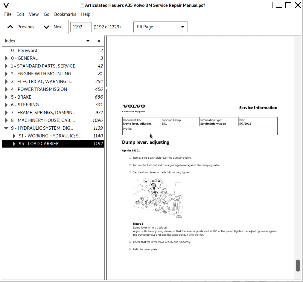
Dump lever, adjusting......1192
Dumping valve (removed), new O-rings......1193
Dumping valve, changing control cable......1195
Dumping valve, removing and mounting......1198
Dumping valve......1200
General......1203
Hoist (dump) cylinder removed, reconditioning......1204
Hoist (dump) cylinder, changing......1210
Hoist cylinder (serial no. 1195)......1213
Hoist cylinder (serial no. 1194)......1214
Hoist cylinders, changing piston rod seals (using 999 3579 and999 3579B)......1217
Load body, adjusting against frame......1222
Load body, changing slide bearing (dump bearing)......1224
Mounting piston rod seals......1228
Articulated Haulers A35 Volvo BM Service Repair Manual
![]()