
John Deere 450, 455, 750, 1520, 1530, 1535, 1560, 1590, 9400 Grain Drills Repair Service Manual (TM159219)
Complete diagnosis & repair technical manual with electrical wiring diagrams for John Deere 450, 455, 750, 1520, 1530, 1535, 1560, 1590, 9400 Grain Drills, with workshop information to maintain, diagnostic, repair, and service like professional mechanics.
John Deere Grain Drills Drills Models 450, 455, 750, 1520, 1530, 1535, 1560, 1590 & 9400 workshop service & repair manual includes:
* Numbered table of contents easy to use so that you can find the information you need fast.
* Detailed sub-steps expand on repair procedure information
* Numbered instructions guide you through every repair procedure step by step.
* Troubleshooting and electrical service procedures are combined with detailed wiring diagrams for ease of use.
* Notes, cautions and warnings throughout each chapter pinpoint critical information.
* Bold figure number help you quickly match illustrations with instructions.
* Detailed illustrations, drawings and photos guide you through every procedure.
* Enlarged inset helps you identify and examine parts in detail.
tm159219 - John Deere Box Drills Technical Manual.pdf
PRODUCT DETAILS:
Total Pages: 1,006 pages
File Format: PDF (bookmarked, ToC, Searchable, Printable, high quality)
Language: English
MAIN SECTIONS
Foreword
Safety and General Information
Safety
Lubricants
General Information
Repair Specifications
Welding
Repair and Welding
Ground Tools, Opener Disks and Press Wheels
Ground Tools-9400 Hoe Drill
Openers-450, 455, 1520 and 9400 Disk Drill
Openers-750
Openers-1530
Openers-1535
Openers-1560 and 1590
Press Wheels-450, 455, 1520 and 9400
Press Wheel, Gauge Wheel and Closing Wheel-750
Gauge Wheel and Closing Wheel-1530
Gauge Wheel and Closing Wheel 1535
Press Wheel, Gauge Wheel and Closing Wheel-1560 and 1590
Electrical and Monitor Systems
Connector Repair
Select Lift Control Repair-455
COMPUTER TRAK™ Monitor System-455, 750,1560 and 1590
Steering Control Repair-750 and 1560
Electronic Population Rate Control
Drive System
Ground Drive Repair
Meter Drive Repair
Fertilizer Gear Box Repair
Grass Seed Drive
Seed Transmission and Drives 1535
Wheel Bearings and Tires
Replace Bearings and Inflate Tires
Hydraulic Systems and Components
Valve and Motor Repair
Cylinder Repair
Multiple Drill Hitches
Identification
Row Markers
Repair
Seed Box Repair
Repair Seed Box
Seed Metering Mechanisms
Seed Metering Mechanisms
Opener Operation, Tests and Adjustments
Opener Theory of Operation
Adjust Ground Tools-9400 Hoe Drill
Adjust Openers-450, 455, 1520 and 9400 Disk Drill
Adjust Openers-750
Adjust Openers-1530 and 1535
Adjust Openers-1560 and 1590
Adjust Press Wheels
Troubleshooting
Electrical System Operation
Wiring Diagrams
Tests and Diagnosis
Drive System
Ground Drive Theory of Operation
Meter Drive Theory of Operation
Grass Seed Drive Theory of Operation
Tests and Adjustments
Hydraulic Systems Operation
Opener Lift System-450 and 9400
Down-Pressure System-455, 750, 1520, 1560 and 1590
Hitch and Transport Systems
Row Marker System
Multiple Drill Hitches
9400 Adjustments
Troubleshooting
Row Markers
Adjustments and Troubleshooting
Dealer Fabricated Tool
Dealer Fabricated Tools
tm159219 - Box Drills
Table of Contents
Foreword
Section 10: Safety and General Information
Group 05: Safety
Recognize Safety Information
Understand Signal Words
Avoid High-Pressure Fluids
Avoid Heating Near Pressurized Fluid Lines
Prepare for Emergencies
Support Machine Properly
Work in Clean Area
Wear Protective Clothing
Service Machines Safely
Work In Ventilated Area
Illuminate Work Area Safely
Replace Safety Signs
Use Proper Lifting Equipment
Use Seat Belt Properly
Practice Safe Maintenance
Use Proper Tools
Remove Paint Before Welding or Heating
Dispose of Waste Properly
Live With Safety
Group 10: Lubricants
Grease
Alternative and Synthetic Lubricants
Lubricant Storage
Group 15: General Information
Unauthorized Modifications
Product Identification—450 Drill
Product Identification—450 Two-Unit Hydraulic Hitch
Product Identification—Three-Unit 455
Product Identification—750 (10 Ft.)
Product Identification—750 (15 Ft.)
Product Identification—750 (20 Ft.)
Product Identification—750 Separate Placement Box
Product Identification—750 Two-Unit Hydraulic Hitch
Product Identification—1520 (15 Ft.)
Product Identification—1520 (20 Ft.)
Product Identification—1530 (15 Ft.)
Product Identification—1535 (15 Ft.)
Product Identification—1560 (10 Ft.)
Product Identification—1560 (15 Ft.)
Product Identification—1560 (20 Ft.)
Product Identification—1560 (Separate Placement Box)
Product Identification—1590 Box Drill (10 ft)
Product Identification—1590 Box Drill (15 ft)
Product Identification—1590 Box Drill (20 ft)
Product Identification—9400 Hoe Drill
Product Identification—9400 Disk Drill
Product Identification—9400 Two-Unit Field Hitch
Product Identification—9400 Three-Unit Field Hitch
Product Identification—9400 Four-Unit Field Hitch
Product Identification—9400 Five-Unit Field Hitch with Endwise Transport
Product Identification—9400 Six-Unit Field Hitch
Product Identification—9400 Endwise Transport Hitch
Machine Specifications—450
Capacity—450 Small Box
Capacity—450 Large Box
Capacity—450 Grass Box
Machine Specifications—455
Capacity—455
Machine Specifications—750
Capacity—750
Machine Specifications—1520
Capacity—1520
Machine Specifications—1530
Capacity—1530
Machine Specifications—1535
Machine Specifications—1560
Machine Dimensions—1590
Machine Capacities—1590
Transport Weights—1590
Machine Specifications—9400
Capacity—9400
Hitch Weights—9400
Group 20: Repair Specifications
Metric Bolt and Screw Torque Values
Unified Inch Bolt and Screw Torque Values
O-Ring Fitting Torques
Section 20: Welding
Group 05: Repair and Welding
Unauthorized Modifications
Frame Repair
Welding
Emergency Crack Repair
Emergency “T” Joint Repair
Skip Welding
Stress Relief (Normalizing)
Section 30: Ground Tools, Opener Disks and Press Wheels
Group 05: Ground Tools—9400 Hoe Drill
Specifications
Shovels
Replace Shovels
Repair Rigid Opener
Repair Spring Cushion Opener
Group 10: Openers—450, 455, 1520 and 9400 Disk Drill
Other Material
Specifications
Repair Cast Iron Boot Assembly—Early Model 450 and 9400 Disk
Replace Double-Disk Blades and Bearings—Cast Iron Boots
Repair Aluminum Boot Assembly
Replace and Adjust Double-Disk Blades on Aluminum Boots
Replace Inside Scrapers
Replace Depth Band—450 and 9400 Disk Drill Only
Replace Single-Disk Boot—450
Replace Single Disk Blade and Bearing—450
Repair TRU-VEE Opener—450
Assemble TRU-VEE Opener—450
Group 11: Openers—750
Essential or Recommended Tools
Specifications
Replace Disk Blades and Bearings
Replace Opener Arm Pivot Bushings
Replace Seed Boot
Group 12: Openers—1530
Replace Disk Blades, Seed Tubes and Guards
Replace Scrapers
Replace Coulter Blade and Bearing—If Equipped
Group 13: Openers—1535
Specifications
TRU-VEE Double Disk Opener MAXEMERGE PLUS MAXEMERGE PLUS is a trademark of Deere & Company Units
Replace TRU-VEE Double Disk Openers and Seed Tube Guard
Replace Scrapers
Group 14: Openers—1560 and 1590
Essential or Recommended Tools
Other Material
Specifications
Replace Disk Openers—1560
Replace Disk Openers —1590
Replace Disk Bearings
Replace Opener Arm Pivot Bushings—1560
Replace Opener Arm Pivot Bushings—1590
Replace Seed Deflectors and Boots—1560
Replace Seed Deflectors and Boots—1590
Group 20: Press Wheels—450, 455, 1520 and 9400
Specifications
Repair Depth Gauging Press Wheel—450
Replace Gang Press Pivot Wheel—450
Repair Gang Press Lift Assembly—450
Repair Press Wheel and Press Wheel Arm—455 and 1520
Repair Press Wheel Gang—9400
Replace Press Wheels—9400
Install Repair Ring—1-3/4 Inch Solid Press Wheel—9400
Construct Installation Band
Attach Repair Ring—9400
Press Wheel Spacers—9400
Group 21: Press Wheel, Gauge Wheel and Closing Wheel—750
Specifications
Replace Closing Wheel Bearing and Arm
Repair Press Wheel Assembly
Time Gauge Wheel Arm to Adjustment Plate
Repair Gauge Wheel Assembly
Group 22: Gauge Wheel and Closing Wheel—1530
Repair Closing Wheels
Repair Gauge Wheel Assembly
Group 23: Gauge Wheel and Closing Wheel 1535
Essential or Recommended Tools
Gauge Wheel Bearing Replacement
Repair Closing Wheel 1535
Group 24: Press Wheel, Gauge Wheel and Closing Wheel—1560 and 1590
Specifications
Replace Closing Wheel Bearing and Arm—1560
Repair Closing Wheel Assembly—1590
Repair Press Wheel Assembly—1560
Repairing Press Wheel Assembly—1590
Repair Gauge Wheel Assembly
Repair Smooth Sided Gauge Wheel Assembly
Section 40: Electrical and Monitor Systems
Group 05: Connector Repair
Essential or Recommended Tools
Service Parts Kits
Replace WEATHER PACK WEATHER PACK is a trademark of Packard Electric. Connector
Replace DEUTSCH DEUTSCH is a trademark of the Deutsch Co. Connectors
Group 10: Select Lift Control Repair—455
Repair Select Lift Control Console
Group 15: COMPUTER TRAKCOMPUTER TRAK is a trademark of Deere & Company. Monitor System—455, 750,1560 and 1590
Repair COMPUTER TRAK Monitor System—Use TM1270
Repair SEEDSTAR SEEDSTAR is a trademark of Deere & Company Monitor System—Use TM1601
Replace Monitor Sensor—750 (New Model), 1560 and 1590 Seed Tube
Replace Monitor Sensor—750 Old Model Seed Tube and 455
Group 20: Steering Control Repair—750 and 1560
Repair Steering Control Console—Two-Unit Hydraulic Hitch
Group 25: Electronic Population Rate Control
Rate Adjust Harness Switch
Electronic Rate Adjust
Section 50: Drive System
Group 05: Ground Drive Repair
Specifications
Repair Ground Drive System—450
Repair Ground Drive System—455
Replace Drive Shear Pin—450, 455, 1520 and 1530
Repair Ground Drive System—750 (10 and 15 Ft.)
Repair Ground Drive System—750 (20 Ft.)
Replace Drive Shear Pin—750, 1560 and 1590
Repair Drive Wheel Disconnect—750, 1560 and 1590 (10 and 15 Ft.)
Repair Ground Drive System—1520, 1530 and 1535
Repair Ground Drive System—1560 and 1590 (10 and 15 Ft.)
Repair Ground Drive System—1560 and 1590 (20 Ft.)
Repair Ground Drive System—9400 Disk and Hoe Drill
Group 10: Meter Drive Repair
Repair Meter Drive System—450
Repair Meter Drive Gears and Sprockets—450
Disassemble, Clean and Inspect Meter Drive Clutch—450
Repair Feed Cups and Shaft—All Drills
Repair Feed Cups and Shaft—1590
Reset Fluted Feed Cups
Repair Fertilizer Feed Shaft—All Drills
Repair Agitator Shaft—All Drills
Repair Countershaft—450
Repair Acremeter—All Drills
Replace Meter Drive Gears and Sprockets—455, 750, 1520, 1530, 1560, 1590 and 9400
Disassemble, Clean and Inspect Meter Drive Clutch—455, 750, 1560 and 1590
Repair Swing Drive Assembly—455 Three-Unit
Repair Telescoping Shaft—455 Three-Unit
Repair Meter Drive System—455, 750, 1560 and 1590
Repair Meter Drive System—750, 1560 and 1590 Separate Placement Box
Repair Meter Drive System—1520 and 1530
Disassemble, Clean and Inspect Meter Drive Clutch—9400
Repair Meter Drive System—9400 Disk
Repair Meter Drive System—9400 Hoe
Group 15: Fertilizer Gear Box Repair
Service Equipment and Tools
Repair Fertilizer Gear Box
Disassemble Gear Box
Repair Spindle
Remove and Inspect Gears and Drives
Replace Gear Box Bearings
Assemble Gear Box Drive Shaft
Install Bearings
Install Spindle and Crown Gear
Group 20: Grass Seed Drive
Repair Grass Seed Drive System—450
Repair Grass Seed Drive System—455, 750, 1560 and 1590
Repair Grass Seed Drive System—1520
Repair Grass Seed Drive System—9400
Group 25: Seed Transmission and Drives 1535
Transmission and Drives
Section 60: Wheel Bearings and Tires
Group 05: Replace Bearings and Inflate Tires
Tire Inflation Pressures
Specifications
Replace Transport Wheel Bearing—450
Replace Caster Wheel Bearing—450 (2 or 3 Unit Hitch)
Replace Wheel Bearing—Single Wheel—455
Replace Wheel Bearing—Dual Wheel—455
Replace Transport Wheel Bearing—750, 1560, 1590 and 9400
Replace Caster Wheel Bearing and Pivot Bushing—750, 1560 and 1590
Replace Wheel Bearing—Pre 1997 1520
Replace Wheel Bearing—(1997— 1520), All 1530 and 1535
Replace Caster Wheel Bearing and Pivot Bearing—9400
Section 70: Hydraulic Systems and Components
Group 05: Valve and Motor Repair
Specifications
Prevent Hydraulic System Contamination
Repair Pressure Control Valve—Old (Pre 1995)
Repair Pressure Control Valve—New (1995 and After)
Single Point Depth Control Valve
Repair Select Lift Valve—455
Repair Marker Sequence Valve—New
Repair Marker Sequence Valve—Old
Repair Selector Control Valve—450, 455
Repair Steering Control System—750 and 1560 Two-Unit Hydraulic Hitch
Repair Steering Motor
Assemble Steering Motor
Hydraulic Diagram—Rockshaft Control—1590
Down-Pressure Hose Routing—1590
Group 10: Cylinder Repair
Essential or Recommended Tools
Service Equipment and Tools
Specifications
Specifications—WYR-LOC and 580 Cylinders
Service Parts Kit
Prevent Hydraulic System Contamination
Remove Hydraulic Cylinders
WYR-LOC Cylinder Identification
Disassemble WYR-LOC Cylinder
Inspect Cylinder Seals and Components—WYR-LOC
Inspect Cylinder Barrel
Assemble Cylinder
Install and Bleed Cylinders
580 Series Cylinder Identification
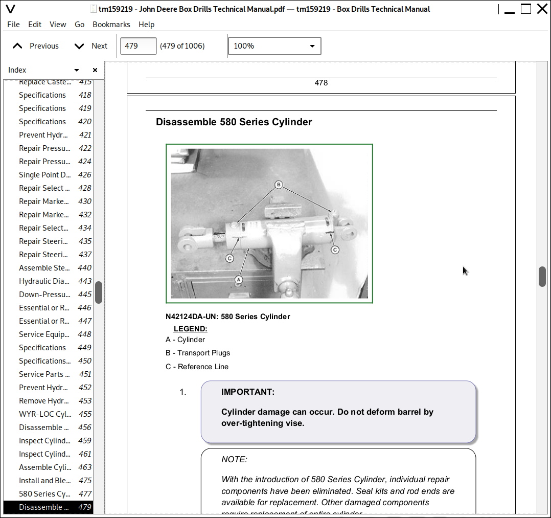
Disassemble 580 Series Cylinder
Inspect Cylinder Seals and Components—580 Series
Inspect Cylinder Barrel
Assemble Cylinder
Install and Bleed Cylinders
Repair Tie Rod Cylinder (John Deere)
Repair Tie Rod Cylinder (Prince)
Replace Cylinder Rod End Seal
Repair Tie Rod Cylinder—3 x 8 In. (Cross)
Repair Tie Rod Cylinder—2-1/2 x 8 In. (Cross)
Install and Bleed Cylinders
Section 80: Multiple Drill Hitches
Group 05: Identification
450 Two-Unit Hydraulic Hitch
450 Three-Unit Mechanical Hitch
455 Two-Unit
455 Three-Unit
750 and 1560 Two-Unit Hydraulic Hitch
750 and 1560 Two-Unit Mechanical Hitch
9400 Two-Unit Field Hitch
9400 Three-Unit Field Hitch
9400 Four-Unit Field Hitch
9400 Five-Unit Field Hitch
9400 Six-Unit Field Hitch
9400 Endwise Transport Hitch
Section 90: Row Markers
Group 05: Repair
Specifications
General Information—Cable Clamps
Repair Front Mounted Marker Assembly—450
Replace Marker Bearing and Disk—450 Rear, 455 and 750
Replace Heavy-Duty Marker Bearing and Disk—Old 750
Replace Marker Bearing and Disk—750, 1520, 1530, 1535, 1560 and 1590
Repair Marker Arm Assembly—750, 1560 and 1590
Assemble Marker Pivot Arm Assembly—750, 1560 and 1590
Replace Marker Breakaway Bolt—1590
Replace Marker Bearing and Disk—9400
Repair Marker Arm—450 Rear, 455 and 9400 Three and Four Unit
Repair Marker Base and Lift Channel—450 Rear, 455 and 9400
Section 100: Seed Box Repair
Group 05: Repair Seed Box
Other Material
Remove Seed Box for Repair
Repair Seed Box
Section 110: Seed Metering Mechanisms
Group 05: Seed Metering Mechanisms
Inspect Radial Bean Meter
Repair Radial Bean Meter
Diagnosing Radial Bean Meter Malfunctions
Inspect and Repair Finger Pickup Meter
Diagnosing Finger Pick-Up Malfunctions
Section 230: Opener Operation, Tests and Adjustments
Group 05: Opener Theory of Operation
Opener Reference—All Drills
Opener Theory of Operation—450, 455, 1520 and 9400
Opener Theory of Operation—750
Opener Theory of Operation—1530 and 1535
Opener Theory of Operation—1560 and 1590
Group 10: Adjust Ground Tools—9400 Hoe Drill
Adjust Down Force—Hoe Drill
Align Openers with Press Wheels
Group 11: Adjust Openers—450, 455, 1520 and 9400 Disk Drill
Specifications
Align Opener Drawbars—450 and 9400 Disk
Align Openers with Press Wheels—9400 Disk Drill
Adjust Rockshafts—9400
Adjust Opener Down Force—450 and 9400 Disk
Position Pressure Rod—450 and 9400 Disk
Adjust Opener Down-Force—455 and 1520
Adjust Inside Scraper—450 (Single Disk)
Adjust Toe Scraper—450 (Single Disk)
Adjust Boot—450 (Single Disk)
Adjust Double-Disk Blades—Cast-Iron Boots
Adjust Double-Disk Blades—Aluminum Boot
Adjust TRU-VEE Opener—450 Only
Checking Opener Adjustments
Group 12: Adjust Openers—750
Specifications
Opener Adjustment Tool
Adjust Gauge Wheel and Seeding Depth
Adjust Gauge Wheel Position
Adjust Press and Closing Wheel Down Force
Adjust Closing Wheel Position
Adjust Seed Boots
Use Alternate Opener Pattern
Alternate Opener Diagram—15 Ft.
Alternate Opener Diagram—20 Ft.
Checking Opener Adjustments
Group 13: Adjust Openers—1530 and 1535
Specifications
Adjust Seeding Depth
Adjust Gauge Wheels
Adjust Down Force
Adjust Closing Wheel—Small Seeds at Shallow Depth
Center (Align) Closing Wheels
Adjust Closing Wheels (Stagger)
Adjust Closing Wheel Down Force
Group 14: Adjust Openers—1560 and 1590
Specifications
Adjust Gauge Wheel and Seeding Depth—1560
AdjustGauge Wheel and Seeding Depth—1590
Adjust Gauge Wheel Position—1560
Adjust Guage Wheel Position—1590
Adjust Press and Closing Wheel Down Force—1560
Adjust Press and Closing Wheel Down Force—1590
Adjust Closing Wheel Position
Adjust Seed Boots—1560
Adjust Seed Boots—1590
Use Alternate Opener Pattern
Alternate Opener Diagram—15 Ft.
Alternate Opener Diagram—20 Ft.
Checking Opener Adjustments
Group 15: Adjust Press Wheels
Adjust Gang Press Pivot Wheel Down-Force—450
Adjust Gang Press Pivot Wheel Alignment—450
Adjust Gang Press Pivot Wheel Exceptions—450
Adjust Depth Gauging Press Wheels
Group 20: Troubleshooting
Openers—450, 455, 1520 and 9400 Drills
Openers—750,1560 and 1590 Drills
Openers—1530 and 1535 Drills
Section 240: Electrical System Operation
Group 05: Wiring Diagrams
Wiring Diagram—Warning Lights (All Pre-1999 Drills)
Wiring Diagram—Warning Lights (All 1999 Drills)
Wiring Harness—Select Lift (Power Adapter)
Select Lift Control—455
Wiring Harness—455 Select Lift (Seven-Pin)
Wiring Harness—455 Select Lift (Seven-Pin-to-Coils)
Wiring Harness—Steering Control (750 and 1560 Two-Unit Hydraulic Hitch)
Wiring Harness Extension—Steering Control (750 and 1560 Two-Unit Hydraulic Hitch)
Wiring Harness—COMPUTER TRAK Monitor—455 (25 Ft.)
Wiring Harness—COMPUTER TRAK Monitor—455 (30 and 35 Ft.)
Wiring Harness—COMPUTER TRAK Monitor—750, 1560 and 1590
Wiring Harness—COMPUTER TRAK Monitor—750 and 1560 Two-Unit Hitch
SEEDSTAR Monitor System
Group 10: Tests and Diagnosis
Electrical Schematic Symbols
Visually Inspect Electrical System
Using a Probe Light
Circuit Types
Circuit Malfunctions
Troubleshooting Circuit Malfunctions
Understanding Electrical vs. Electronic Circuits
Intermittent Electronic Problems
Abbreviations and Explanations—Wiring Diagrams
Light Enhancement Module—Theory of Operation
Schematic—Light Enhancement Module (1999— )
Select Lift Control—System Diagnosis (455 2-Unit)
Select Lift Control—System Diagnosis (455 3-Unit)
Theory of Operation—Select Lift (455 Two-Unit)
Theory of Operation—Select Lift (455 Three-Unit)
Schematic—Select Lift (455 Two-Unit)
Schematic—Select Lift (455 Three-Unit)
Section 250: Drive System
Group 05: Ground Drive Theory of Operation
Specifications
Ground Drive Power Flow—450
Ground Drive Power Flow—455
Ground Drive Power Flow—750 (10 and 15 Ft.)
Ground Drive Power Flow—750 (20 Ft.)
Ground Drive Power Flow—1520, 1530 and 1535
Ground Drive Power Flow—1560 and 1590 (10 and 15 Ft.)
Ground Drive Power Flow—1560 and 1590 (20 Ft.)
Ground Drive Power Flow—9400
Group 10: Meter Drive Theory of Operation
Meter Drive Power Flow—450
Meter Drive Power Flow—455, 750, 1560 and 1590 (10, 15 and 20 Ft.)
Meter Drive Power Flow—750, 1560 and 1590 Separate Placement Box
Meter Drive Power Flow—1520 and 1530
Meter Drive Power Flow—9400 Disk
Meter Drive Power Flow—9400 Hoe
Feed Cup—Theory of Operation
Fertilizer Feed Shaft—Theory of Operation
Group 15: Grass Seed Drive Theory of Operation
Grass Seed Drive Power Flow—450
Grass Seed Drive Power Flow—455, 750, 1560 and 1590
Grass Seed Drive Power Flow—1520
Grass Seed Drive Power Flow—9400
Group 20: Tests and Adjustments
Adjust Feed Cups
Reset Feed Cups
Adjust Product Flow Index Setting
Test Grain Feed Shaft
Test Grass Seed Feed Shaft
Test Acremeter Accuracy
Check Drive System Chains
Check for Half-Speed Drive—450, 455, 750, 1520, 1560 and 1590
Check for Half-Speed Drive—9400
Check for Proper Fertilizer Drive Sprocket
Check Fertilizer Gear Case Setting
Performing Accurate Rate Checks
Rate Check—Method 1
Rate Check—Method 2
Check Seed Population—1530
Troubleshooting—Delivery System
Section 270: Hydraulic Systems Operation
Group 05: Opener Lift System—450 and 9400
Opener Lift Hose Routing—450 Series
Opener Lift Hose Routing—9400 Series
Opener Lift Circuit Operation
Troubleshooting
Group 06: Down-Pressure System—455, 750, 1520, 1560 and 1590
Down-Pressure Hose Routing—455 Series
455 Series Down Pressure System - Type Identification
455 Series Down Pressure System Schematic - Closed Center System (SN -2382) - Type A
455 Series Down Pressure System Schematic - Closed Center System (SN 2383-2961) - Type B
455 Series Down Pressure System Schematic - Closed Center System (SN 2962-) - Type C
455 Series Down Pressure System Schematic - Open Center System (SN -2382) - Type D
455 Series Down Pressure System Schematic - Open Center System (SN 2383-2961) - Type E
455 Series Down Pressure System Schematic - Open Center System (SN 2962-) - Type F
455 Series Down Pressure System Schematic - Open/Closed Center System (SN -2382) - Type G
455 Series Down Pressure System Schematic - Open/Closed Center System (SN 2383-2961) - Type H
455 Series Down Pressure System Schematic - Open/Closed Center System (SN 2962-) - Type I
Down-Pressure Hose Routing—750, 1560 and 1590
Down-Pressure Hose Routing—1520 Series
Single-Point Depth Stop Down-Pressure Circuit Operation (750)
Active Down-Pressure Circuit and Valve Operation
Open-Center Kit
Select Lift Circuit and Valve Operation (455)
Troubleshooting—Tractor With Closed-Center Hydraulics
Troubleshooting—Tractor With Open-Center Hydraulics (Single-Point Depth Stop)
Troubleshooting—Tractor With Open-Center Hydraulics (Active Down-Pressure)
Group 10: Hitch and Transport Systems
Two-Unit Hydraulic Folding Hitch Hose Routing—450 Series
Fold and Cart Lift Hose Routing—455 Series
Two-Unit Hydraulic Folding Hitch Hose Routing—750 and 1560
Transport Wheels and Hitch Lift Hose Routing—9400 Series
450 Hydraulic Folding Hitch Circuit Operation
455 Folding Circuit Operation
750 and 1560 Two-Unit Hydraulic Hitch Operation
9400 Transport Wheels and Endwise Hitch Operation
Steering Solenoid Valve Operation (750 and 1560)
Steering Motor Operation (750 and 1560)
Group 15: Row Marker System
Row Marker Hose Routing—450 Series
Row Marker Hose Routing—455 Series
Row Marker Hose Routing—750, 1560 and 1590
Row Marker Hose Routing—1520 and 1530
Row Marker Hose Routing—9400 Series
Row Marker Circuit Diagram and Operation
Row Marker Sequence Valve Operation—Early Models
Row Marker Sequence Valve Operation—Later Models
Fold/Marker Selector Valve Operation (450 and 455)
Troubleshooting
Section 280: Multiple Drill Hitches
Group 05: 9400 Adjustments
Adjust Center Lift—9400 Two- and Four-Unit Hitches
Adjust Hitch Lift—9400 Three-, Five-, and Six-Unit Hitches
Adjust Transport Tire Brake—9400
Adjust Endwise Transport Hitch
Adjust Hitch Height—Endwise Transport
Adjust Caster Wheel Linkage
Group 10: Troubleshooting
450 and 455 Multi-Unit Hitches
750 and 1560 Two-Unit Hydraulic Hitch
9400 Hitches
Section 290: Row Markers
Group 05: Adjustments and Troubleshooting
Adjust Markers
Section 299: Dealer Fabricated Tool
Group 05: Dealer Fabricated Tools
DFNX1592A Drive Shaft Support Tool
John Deere 450, 455, 750, 1520, 1530, 1535, 1560, 1590, 9400 Grain Drills Repair Service Manual (TM159219)
![]()