
John Deere Planters Models 1107, 1109, 1111, 1113 Repair Service Manual (TM804019)

John Deere Planters Models 1107, 1109, 1111, 1113 Repair Service Manual (TM804019)
tm804019 - 1100 Series Planters (100000 - ) Technical Manual.pdf
Complete Repair Service Technical Manual for John Deere Planters Models 1107, 1109, 1111, 1113, with all the shop information to maintain, diagnostic, repair, refurbish/rebuild like professional mechanics.
John Deere 1107, 1109, 1111, 1113 Planters (SN.100000-) workshop technical manual (repair) includes:
* Numbered table of contents easy to use so that you can find the information you need fast.
* Detailed sub-steps expand on repair procedure information
* Numbered instructions guide you through every repair procedure step by step.
* Troubleshooting and electrical service procedures are combined with detailed wiring diagrams for ease of use.
* Notes, cautions and warnings throughout each chapter pinpoint critical information.
* Bold figure number help you quickly match illustrations with instructions.
* Detailed illustrations, drawings and photos guide you through every procedure.
* Enlarged inset helps you identify and examine parts in detail.
Total Pages: 325 pages
File Format: PDF (bookmarked, ToC, Searchable, Printable, high quality)
Language: English
MAIN SECTIONS
Foreword
Model Identification and Chassis Covered in this Manual
General Information
safety
Lubricants
General Information
Specifications
Planting Units (Seeds)
Row Units
Vacuum System
Vacuum Seed Meters
Closing Wheels
Gauge Wheels
Offset Seed Disks
Fertilizer Unit
Fertilizer Meters
Offset Fertilizer Disks
Cutter Disks
Row Markers
Row Markers
Transmissions
Clutch
Wheel Hub
Distribution Sprockets
Miscellaneous
Repairing Polyethylene Tank
Dealer Fabricated Tools
Dealer Fabricated Tools
Electrical System
General Information
Theory of Operation
Schematic
Electrical Diagnosis
Hydraulic System
General Information
Vacuum Turbine Motor
Hydraulic Valves
Lift and Row Marker Hydraulic Cylinders
Hydraulic System Schematics
Hydraulic Diagnosis
tm804019 - 1100 Series Planters (100000 - )100000 Technical Manual
Table of Contents
Foreword
Model Identification and Chassis Covered in this Manual
Section 05: General Information
Group 05: safety
Work In Ventilated Area
Work in Clean Area
Recognize Safety Information
Handle Chemicals Safely
Signal Words
Follow Safety Instructions
Handle Fluids with Care—Prevent Fires
Emergencies
Hazardous Asbestos Dust
Practice Safe Service Procedures
High-Pressure Fluids
Park Machine Safely
Appropriate Machine Support
Use Protective Clothing
Service Machines Safely
Illuminate Work Area Safely
Replacing Safety Labels
Adequate Lifting and Suspension Equipment
Remove Paint Before Welding or Heating
Avoid Heating Areas Near Pressurized Fluid Lines
Safe Tire Servicing
Use Proper Tools
Dispose of Residues Properly
Safety—Live with it
Group 10: Lubricants
Grease
Gear Oil
Alternative and Synthetic Lubricants
Using Graphite Powder
Storage of Lubricants
Group 15: General Information
Unauthorized Modification
Identification View
Parking Planter Safely
Metric Bolt Torque Values
Unified Inch Bolt Torque Values
Mounting and Installing Face Seal Fittings—All Pressure Applications
Metric Face Seal Fitting Torque Chart—Standard Pressure Applications
Metric Face Seal Fitting Torque Chart—High Pressure Applications
SAE Face Seal Fitting Torque Chart—Standard Pressure Applications
SAE Face Seal Fitting Torque Chart—High Pressure Applications
External Hex Plug Torque Chart
Group 20: Specifications
Coupling
Tires
Chassis
Transmission
Weight
Seed Box
Fertilizer Box
Default Row Spacing Settings
Dimensions
Required Tractor Features
Section 10: Planting Units (Seeds)
Group 05: Row Units
Removing and Installing Row Units - RadialMeter Planters
Removing and Installing Row Units—VacuMeter Planters
Group 10: Vacuum System
Special Tools
Other Material
Specifications
How to Zero the Vacuum Blower Pressure Gauge
Setting the Vacuum Level
Checking Row Vacuum Level
Group 15: Vacuum Seed Meters
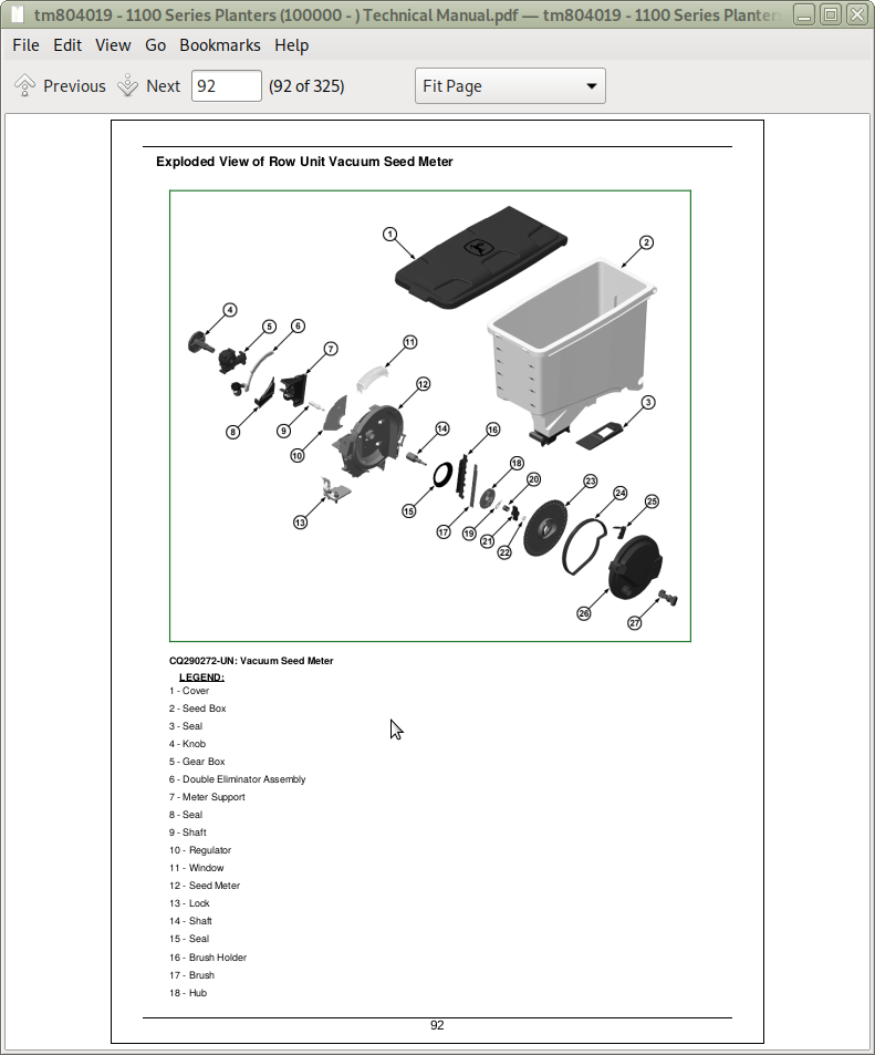
Exploded View of Row Unit Vacuum Seed Meter
Removing and Installing Seed Disk
Inspection of Vacuum Meter
Removing and Installing Vacuum Meter Brush
Adjusting Seed Meter Hub
Repairing Shaft Drive
Group 20: Closing Wheels
Other Material
Exploded View of Closing Wheel
Group 25: Gauge Wheels
Specifications
Gauge Wheel Exploded View
Installing Gauge Wheel
Installing Gauge Wheel Hub
Group 30: Offset Seed Disks
Special Tools
Specifications
Exploded View of Offset Seed Disks
Removing Offset Seed Disks
Replacing Offset Seed Disk Bearing
Installing Offset Seed Disks
Section 15: Fertilizer Unit
Group 05: Fertilizer Meters
Specifications
Exploded View of Fertilizer Meter
Removing and Installing Fertilizer Meters
Assembling and Disassembling of Fertilizer Meter
Group 10: Offset Fertilizer Disks
Special Tools
Specifications
Exploded View of Fertilizer Disk
Removing Offset Fertilizer Disks
Replacing Offset Fertilizer Disk Bearing
Installing Offset Fertilizer Disks
Group 15: Cutter Disks
Special Tools
Specifications
Exploded View of Cutter Disk
Adjusting Cutter Disk Cone Bearings
Section 20: Row Markers
Group 05: Row Markers
Exploded View of Single Row Marker
Section 25: Transmissions
Group 05: Clutch
Repairing Clutch
Group 10: Wheel Hub
Specifications
General View of Wheel Hub
Removing and Installing Wheel Hub
Removing and Installing Wheel Hub Bearings—Single Wheels
Removing and Installing Wheel Hub Bearings—Double Wheels
Group 15: Distribution Sprockets
Fertilizer Distribution Sprockets
Seed Distribution Sprockets
Section 35: Miscellaneous
Group 05: Repairing Polyethylene Tank
Essential or Recommended Tools
Repairing Polyethylene Plastic
Installing RIVNUT RIVNUT is a trademark of Engineered Products Inc. Threaded Inserts
Section 99: Dealer Fabricated Tools
Group 05: Dealer Fabricated Tools
DFAXT1 — Adjusting screw tool
Section 240: Electrical System
Group 10: General Information
Using Electrical Section
Electrical Designators
Electrical System Visual Inspection
Electrical Schematic Symbols
Know the System
Electrical System
Group 20: Theory of Operation
Theory of Operation of Row Marker System (Electro-Hydraulic)
Group 30: Schematic
Row Marker Electrical System Diagram (Electro-Hydraulic)
Group 50: Electrical Diagnosis
Row Marker Electrical System Diagnosis (Electro-Hydraulic)
Section 270: Hydraulic System
Group 05: General Information
High-Pressure Fluids
Relieving Hydraulic System Pressure
Hydraulic Symbols
Group 10: Vacuum Turbine Motor
Other Material
Specifications
Inspecting Vacuum Blower Motor
Removing and Installing Vacuum Blower Motor
Repairing Vacuum Blower Motor
Repairing Central Seed Box Blower Motor
Group 15: Hydraulic Valves
Removing and Installing Cartridge Valves
Flow Control Valve
Row Marker Valve
Group 20: Lift and Row Marker Hydraulic Cylinders
Removing and Installing Lift Cylinder
Repairing Planter Lift Cylinder
Removing and Installing Single Row Marker Cylinder
Repairing Row Marker Cylinder
Group 25: Hydraulic System Schematics
Vacuum System
Row Marker Hydraulic System Diagram (Hydraulic)
Row Marker Hydraulic System Diagram (Electro-Hydraulic)
Group 30: Hydraulic Diagnosis
Checking Internal Leakage of Planter Lift Cylinder
Checking Row Marker Valve and Cylinder
Row Marker Hydraulic System Diagnosis (Hydraulic)
Row Marker Hydraulic System Diagnosis (Electro-Hydraulic)
![]()