
John Deere 1770NT, 1770NT CCS 12-Row Planter Repair Service Manual (TM2183)
John Deere 1770NT, 1770NT CCS 12-Row Planter Repair Service Manual (TM2183)
tm2183 - 1770NT and1770NT CCS12-Row Planter Repair Technical Manual.pdf
Complete Repair Service Technical Manual for John Deere 12-Row Planters Models 1770NT and 1770NT CCS (SN.–740100), with all the workshop information to maintain, diagnose, repair, and service like professional mechanics.
John Deere 12-Row Planters Models 1770NT and 1770NT CCS workshop technical manual (repair) includes:
* Numbered table of contents easy to use so that you can find the information you need fast.
* Detailed sub-steps expand on repair procedure information
* Numbered instructions guide you through every repair procedure step by step.
* Troubleshooting and electrical service procedures are combined with detailed wiring diagrams for ease of use.
* Notes, cautions and warnings throughout each chapter pinpoint critical information.
* Bold figure number help you quickly match illustrations with instructions.
* Detailed illustrations, drawings and photos guide you through every procedure.
* Enlarged inset helps you identify and examine parts in detail.
Total Pages: 894 pages
File Format: PDF (bookmarked, ToC, Searchable, Printable, high quality)
Language: English
MAIN SECTIONS
Foreword
General Information
Safety
Lubricants
General Information
Vacuum System
Vacuum System
Central Commodity System
Seed Tanks and Manifolds
Seed Delivery Hose
Central Commodity System Fan
Planting Units
MaxEmerge Plus™ / MaxEmerge XP™ Vacuum Seed Meters
MaxEmerge Plus™ / MaxEmerge XP™ Plateless Seed Meters
PRO-SERIES™ / Pro-Series XP™ Vacuum Seed Meters
PRO-SERIES™ / Pro-Series XP™ Plateless Seed Meters
Seed Openers
Closing Wheels
Row Tillage
Insecticide/Herbicide Meter
Mechanical Row Unit Down Force
Pneumatic Row Unit Down Force
Hitch and Frame
Repair and Welding
Hitch Pads
Wheel Module Repair
Row Marker
Loading Platform
Electrical
Connector Repair
Frame Control Box
Relays, Sensors, and Switches
Lighting Repair
Drives
Specifications
Drive Wheels
Seed Drive Transmission
Half-Width Disconnect
Drillshaft
Variable Rate Drive
Fertilizer and Pesticide Systems
Liquid Fertilizer System
Variable Rate Fertilizer
Pesticide System
Hydraulics
General Information
Motors
Cylinders
Valve Block
Valves
Miscellaneous
Miscellaneous
Polyethylene Tank Repair
Dealer Fabricated Tools
tm2183 - 1770NT and1770NT CCS12-Row Planter Repair
Table of Contents
Foreword
Section 10: General Information
Group 05: Safety
Recognize Safety Information
Understand Signal Words
Handle Fluids Safely—Avoid Fires
Prepare for Emergencies
Avoid Harmful Asbestos Dust
Practice Safe Maintenance
Avoid High-Pressure Fluids
Service Accumulator Systems Safely
Park Machine Safely
Support Machine Properly
Wear Protective Clothing
Use Steps and Handholds Correctly
Handle Agricultural Chemicals Safely
Avoid Contact with Agricultural Chemicals
Clean Vehicle of Hazardous Pesticides
Work in Clean Area
Service Machines Safely
Work In Ventilated Area
Illuminate Work Area Safely
Replace Safety Signs
Use Proper Lifting Equipment
Remove Paint Before Welding or Heating
Servicing Electronic Control Units
Welding Near Electronic Control Units
Keep Electronic Control Unit Connectors Clean
Keep Electronic Control Unit Connectors Clean
Avoid Heating Near Pressurized Fluid Lines
Service Tires Safely
Use Proper Tools
Construct Dealer-Made Tools Safely
Dispose of Waste Properly
Live With Safety
Group 10: Lubricants
Grease
Gear Oil
Alternative and Synthetic Lubricants
Lubricant Storage
Group 15: General Information
Service Information Bulletins
Unauthorized Modifications
Specifications
Dimensions— Raised Field Position
Dimensions—Folded Transport Position
Record Serial Number
Sealants and Adhesives Cross-Reference Chart
Metric Bolt and Screw Torque Values
Unified Inch Bolt and Screw Torque Values
Face Seal Fittings Assembly and Installation—All Pressure Applications
Metric Face Seal Fitting Torque Chart—Standard Pressure Applications
SAE Face Seal Fitting Torque Chart—Standard Pressure Applications
Section 20: Vacuum System
Group 05: Vacuum System
Essential or Recommended Tools
Other Material
Specifications
Adjust Vacuum Gauge
Check Row Vacuum — MaxEmerge Row Units
Check Row Vacuum — Pro-Series Row Units
Vacuum Manifold Blower System
Vacuum Manifold Tube Orifice Locations
Clean Vacuum Manifold System
Repair Vacuum Monitoring Assembly —Two Vacuum Gauges
Repair Vacuum Monitoring Assembly with SeedStar™
Remove and Install Vacuum Blower Assembly (S.N. —715100)
Remove and Install Vacuum Blower Motor (S.N. —715100)
Remove and Install Vacuum Blower Motor (S.N. 715101—)
Section 25: Central Commodity System
Group 05: Seed Tanks and Manifolds
Other Material
Specifications
Service Parts Kits
Remove and Install Central Commodity Seed Tank
Remove and Install Refuge Plus Third Tank
Tank Repair
Seal Central Commodity System Tanks To Prevent Water Leakage
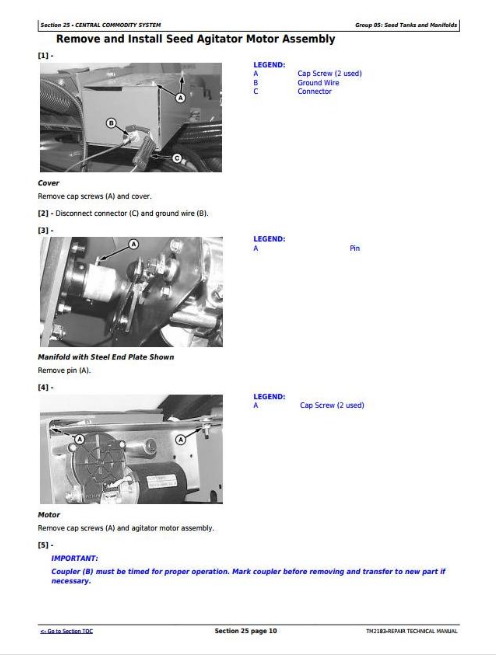
Remove and Install Seed Agitator Motor Assembly
Remove and Install Seed Delivery Manifold Seal
Remove and Install Seed Delivery Manifold Nozzle
Repair Central Commodity System Seed Tank Manifold (with Steel End Plates)
Repair Central Commodity System Seed Tank Manifold (with Plastic End Plates)
Remove and Install Seed Tank Lid Ring and Seal
Group 10: Seed Delivery Hose
Other Material
Remove and Install Seed Delivery Hose
Repair Seed Delivery Hose
Group 15: Central Commodity System Fan
Specifications
Remove and Install Central Commodity System Blower Fan (S.N. —715100)
Remove and Install Central Commodity System Blower Fan (S.N. 715101—)
Repair Central Commodity System Blower Fan Assembly (S.N. —715100)
Repair Central Commodity System Blower Fan Assembly (S.N. 715101—)
Section 30: Planting Units
Group 05: MaxEmerge Plus™ / MaxEmerge XP™ Vacuum Seed Meters
Essential or Recommended Tools
Other Material
Specifications
Remove Vacuum Meter
Vacuum Meter Field Test
Vacuum Seed Meter Exploded View
Repair Vacuum Meter
Inspect Vacuum Meter
Remove and Install Vacuum Meter Brush
Adjust Vacuum Meter Baffle
Inspect Seed Disk
Adjust Meter Hub
Install New Vacuum Seal
Install Knockout Assembly
Install Double Eliminator for ProMax 40, Small Sweet Corn, or Edible Bean Disks
Install Seed Disk
Repair MaxEmerge XP™ Pro-Shaft Drive
Adjust MaxEmerge XP™ Pro-Shaft Drive-to-Meter Alignment
Remove and Install RowCommand Row Unit Clutch with Chain Drive
Adjust Chain Drive-to-Meter Drive Alignment
Group 10: MaxEmerge Plus™ / MaxEmerge XP™ Plateless Seed Meters
Specifications
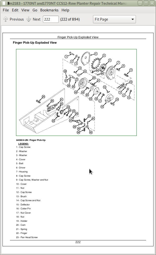
Finger Pick-Up Exploded View
Inspect Finger Pick-Up
Remove and Install Finger Pick-Up
Disassemble Feed Cup
Assemble Feed Cup
Install Feed Cup
Disassemble Radial Bean Meter
Assemble Radial Bean Meter
Group 15: PRO-SERIES™ / Pro-Series XP™ Vacuum Seed Meters
Essential or Recommended Tools
Other Material
Specifications
PRO-SERIES™ / Pro-Series XP™ Row Unit Vacuum Seed Meter Exploded View
Remove and Install Vacuum Meter Seal
Remove and Install Vacuum Meter
Remove and Install Seed Disk
Remove and Install Double Eliminator Plate
Repair Vacuum Meter
Inspect Vacuum Meter
Remove and Install Knockout Assembly
Remove and Install Vacuum Meter Brush
Adjust Meter Hub
Install Dust Seal
Adjust Meter Latch
Repair Pro-Shaft™ Drive
Group 20: PRO-SERIES™ / Pro-Series XP™ Plateless Seed Meters
Specifications
Finger Pick-Up Meter Exploded View
Inspect Finger Pick-Up Meter
Disassemble and Assemble Finger Pick-Up Meter
Radial Bean Meter Exploded View
Disassemble Radial Bean Meter
Assemble Radial Bean Meter
Group 25: Seed Openers
Essential or Recommended Tools
Other Material
Specifications
MaxEmerge Double Disk Opener Exploded View
PRO-SERIES Double Disk Opener Exploded View
High Performance Row Unit Double Disk Opener Exploded View
MaxEmerge XP Runner Opener (S.N. 730101— ) Exploded View
Remove and Install Seed Tube
Inspect and Adjust Seed Opener Blades
Replace Seed Opener Blades and Seed Tube Guard
Gauge Wheels— Exploded View (S.N. —710100)
Gauge Wheels—Exploded View (S.N. 710101— )
Gauge Wheel Bearing Replacement (S.N. —710100)
Gauge Wheel Bearing Replacement (S.N. 710101— )
Remove and Install Gauge Wheel Depth Adjusting Handle
Adjust Gauge Wheels
Replace Scrapers
Replace Heavy-Duty Scrapers
Replace Rigid Scrapers
Group 30: Closing Wheels
Other Material
Specifications
MaxEmerge™ Closing Wheels Repair
PRO-SERIES Closing Wheels Repair
Center Closing Wheels
Adjust Closing Wheel Spacing
Stagger Closing Wheels
Adjust Closing Wheel Down Force
Group 35: Row Tillage
Other Material
Specifications
Adjust Coulter Bearing
Disassemble and Assemble Unit Mounted Row Cleaner Unit with Tapered Wheels
Remove and Install Floating Row Cleaner for Unit Mounted Coulter
Group 40: Insecticide/Herbicide Meter
Other Material
Specifications
Calibrate Insecticide/Herbicide Meter
Insecticide/Herbicide Meter Drive Alignment
Group 45: Mechanical Row Unit Down Force
Specifications
Remove and Install Row Unit
Remove and Install Heavy-Duty Down Force Spring Assembly
Repair Heavy-Duty Down Force Spring Assembly (Regular Parallel Arms)
Repair Heavy-Duty Down Force Spring Assembly (Long Parallel Arms)
Group 46: Pneumatic Row Unit Down Force
Other Material
Specifications
Depressurize Pneumatic Down Force System
Adjust and Inspect Pneumatic Down Force
Install Integrated Pneumatic Down Force Air Pressure Gauges
Remove and Install Integrated Pneumatic Down Force Control Valve
Disassemble and Assemble Pneumatic Down Force Control Valve
Remove and Install Pneumatic Down Force Control Valve Poppet
Remove and Install Integrated Pneumatic Down Force Air Reservoir
Integrated Pneumatic Down Force Air Compressor—Exploded View
Cab-Mounted Pneumatic Down Force Air Compressor—Exploded View
Remove and Install Integrated Pneumatic Down Force Air Compressor
Remove and Install Air Compressor Filter
Remove and Install Air Compressor Isolators
Remove and Install Hydraulically Driven Air Compressor Filter
Remove and Install Hydraulically Driven Air Compressor
Disassemble and Assemble Hydraulically Driven Air Compressor
Section 35: Hitch and Frame
Group 05: Repair and Welding
Frame Repair
Welding
Emergency Crack Repair
Emergency “T” Joint Repair
Skip Welding
Stress Relief (Normalizing)
Group 10: Hitch Pads
Specifications
Remove and Install Hitch Pads
Group 15: Wheel Module Repair
Other Material
Specifications
Center Wheel Frame Exploded View
Wing Wheel Frame Exploded View
Axle and Hub Assembly (8-Bolt)
Axle and Hub Assembly (6-Bolt)
Remove and Install Center Frame Wheel Assembly
Remove and Install Wing Wheel Assembly
Adjust Tire Scraper
Group 20: Row Marker
Specifications
Remove and Install Row Marker
Disassemble and Assemble Row Marker Disk and Arms
Disassemble and Assemble Row Marker Pivot
Replace Marker Breakaway Bolt
Adjust Marker Length
Adjust Marker Disk
Group 25: Loading Platform
Specifications
Remove and Install Loading Platform Step
Section 40: Electrical
Group 05: Connector Repair
Essential or Recommended Tools
Other Material
Use Electrical Insulating Compound
Using High-Pressure Washers
Repair Procedure R-A
Repair Procedure R-B
Repair Procedure R-C
Repair Procedure R-D
Repair Procedure R-E
Repair Procedure R-F
Repair Procedure R-G
Repair Procedure R-I
Repair Procedure R-J
Repair Procedure R-K
Repair Procedure R-M
Repair Procedure R-N
Repair Procedure R-T
Repair Procedure R-AA
Repair Procedure R-AE
Group 10: Frame Control Box
Remove and Install Relay
Test Relay
Remove and Install Circuit Board
Remove and Install Toggle Switch
Group 15: Relays, Sensors, and Switches
Other Material
Specifications
Replace Marker Switch
Adjust Marker Switch
Replace Fold Control Switch (S.N. —710100)
Replace Fold Control Switch (S.N. 710101—)
Replace Central Commodity System Cleanout Switch
Replace Central Commodity System Push Button Shut-Off Switch
Remove and Install Seed Level Sensor
Replace Integrated Pneumatic Down Force Compressor Pressure Switch
Remove and Install Height Sensor
Remove and Install Gauge Wheel Down Force Sensor
Remove and Install Sensor Node Controllers (SeedStar XP only)
Remove and Install Seed Tube Sensor
Remove and Install Integrated Pneumatic Down Force Pressure Sensor
Remove and Install Vacuum Sensor
Remove and Install Wheel Motion Sensor
Remove and Install Hopper Level Sensor
Remove and Install Liquid Fertilizer Sensor
Remove and Install Variable Rate Fertilizer Pump Speed Sensor
Remove Variable Rate Fertilizer Cam Position Sensor
Install Variable Rate Fertilizer Cam Position Sensor
Remove and Install Variable Rate Drive Motor Speed Sensor
Relay Identification
Group 20: Lighting Repair
Repair Red Warning Lamp—1770NT
Repair Amber Warning Lamp—1770NT
Amber Warning Lamp—1770NT CCS
Red Warning Lamp—1770NT CCS
Section 50: Drives
Group 05: Specifications
Drive Chains Specifications
Shear Pin Specifications
Sprocket Specifications
Group 10: Drive Wheels
Transmission Drive Wheel Exploded View
Group 15: Seed Drive Transmission
Specifications
Seed Drive Transmission Exploded View
Remove and Install Seed Drive Transmission
Adjust Seed Drive Transmission
Check and Adjust Transmission Spur Gear Backlash
Group 20: Half-Width Disconnect
Other Material
Specifications
Remove and Install Half-Width Disconnect Clutch
Disassemble and Assemble Half-Width Disconnect Clutch
Group 25: Drillshaft
Remove and Install Wing Frame Drillshaft
Remove and Install Center Frame Drillshaft (Left-Hand Side)
Remove and Install Center Frame Drillshaft (Right-Hand Side)
Remove and Install Upper Jackshaft
Align Drillshaft Coupler and Flex Shaft
Sprocket Location Drawings
Group 30: Variable Rate Drive
Variable Rate Drive
Section 60: Fertilizer and Pesticide Systems
Group 05: Liquid Fertilizer System
Essential or Recommended Tools
Other Material
Specifications
Flush Fertilizer System
Remove and Install Fertilizer Tank
Replace Fertilizer Tank Fitting
Adjust Pump Number Setting
Fertilizer Drive Wheel Exploded View
Adjust Contact Link
Fertilizer Pump Repair
Fertilizer Pump Lubrication
Remove and Install Fertilizer Flow Divider
Repair Fertilizer Flow Divider
Remove and Install Liquid Fertilizer Block Manifold
Repair Liquid Fertilizer Block Manifold
Remove and Install Liquid Fertilizer In-Line Orifice
Remove and Install Liquid Fertilizer Coupler
Remove and Install Liquid Fertilizer Check Valve
Remove and Install Liquid Fertilizer Delivery Tube
Repair Double-Disk Fertilizer Opener
Repair Single-Disk Fertilizer Opener
Bottom Mounted Single-Disk Fertilizer Opener
Frame Mounted Single-Disk Fertilizer Opener (S.N. —720100)
Frame Mounted Single-Disk Fertilizer Opener (S.N. 720101—)
Group 10: Variable Rate Fertilizer
Other Material
Specifications
Remove and Install Variable Rate Fertilizer Pump
Variable Rate Fertilizer Pump Exploded View
Variable Rate Fertilizer Pump Repair
Replace Variable Rate Drive Pump Crankcase Seal
Group 15: Pesticide System
Pesticide Tanks
Remove and Install Pesticide Tank
Repair Pesticide Tank
Section 70: Hydraulics
Group 00: General Information
Relieve Hydraulic System Pressure
Group 05: Motors
Other Material
Specifications
Inspect Vacuum Blower Motor
Repair Vacuum Blower Motor (S.N. 710101—715100)
Repair Vacuum Blower Motor (S.N. 715101—745100)
Repair Vacuum Blower Motor (S.N. 745101—)
Inspect Central Commodity System Blower Motor
Repair Central Commodity System Blower Motor—Type A
Remove and Install Central Commodity System Blower Motor—Type B
Repair Central Commodity System Blower Motor—Type B
Group 10: Cylinders
John Deere 100 Series Hydraulic Cylinder Repair—Use CTM
John Deere 120 Series Hydraulic Cylinder Repair—Use CTM
Remove and Install Main Frame Wheel Cylinder
Remove and Install Wing Wheel Cylinder
Remove and Install Wing Fold Cylinder
Remove and Install Marker Cylinder
Group 15: Valve Block
Valve and Port Locations
Group 20: Valves
Specifications
Flow Control Valve
Remove and Install Solenoid Valves
Inspect Solenoid Valve Body
Remove and Install Cartridge Valves
Group 25: Miscellaneous
Hydraulic Fitting Torque Values
Remove and Install Hydraulic Oil Cooler
Section 80: Miscellaneous
Group 05: Polyethylene Tank Repair
Essential or Recommended Tools
Repair Polyethylene Plastic
Install Bollhoff Rivnut® Threaded Inserts
Section 99: Dealer Fabricated Tools
Group 05: Dealer Fabricated Tools
DFAXT1—Set Screw Wrench
![]()