
Articulated Haulers A30 Volvo BM Service Repair Manual

Complete repair service manual with Electrical Wiring Diagrams for Articulated Haulers A30 Volvo BM, with all the technical information to maintain, diagnose, repair, and rebuild like professional mechanics.
Articulated Haulers A30 Volvo Constructions workshop service repair manual includes:
* Numbered table of contents easy to use so that you can find the information you need fast.
* Detailed sub-steps expand on repair procedure information
* Numbered instructions guide you through every repair procedure step by step.
* Troubleshooting and electrical service procedures are combined with detailed wiring diagrams for ease of use.
* Notes, cautions and warnings throughout each chapter pinpoint critical information.
* Bold figure number help you quickly match illustrations with instructions.
* Detailed illustrations, drawings and photos guide you through every procedure.
* Enlarged inset helps you identify and examine parts in detail.
MAIN SECTIONS
0 - GENERAL
1 - STANDARD PARTS, SERVICE
2 - ENGINE WITH MOUNTING AND EQUIPMENT
3 - ELEC. SYSTEM; WARNING SYSTEM; INFORMATION SYSTEM; INSTRUMENTS
4 - POWER TRANSMISSION
5 - BRAKE
6 - STEERING
7 - FRAME; SPRINGS; DAMPING; AXLE SUSPENSION; WHEEL_TRACK UNIT
8 - MACHINERY HOUSE; CAB; EXTERIOR TRIM PARTS ANYWHERE
9 - HYDRAULIC SYSTEM; DIGGING_HANDLING_GRADING EQUIPM.; MISC EQUIPM
Articulated Haulers A30 Volvo BM Service Repair Manual.PDF
PRODUCT DETAILS:
Pages: 1,105
File Format: PDF (Windows & Mac & Linux)
Language: English
TABLE OF CONTENTS
0 - Foreword................2
0 - GENERAL................3
00 - DESCRIPTION; COMPLETE MACHINE................4
Description................5
03 - SPECIFICATIONS................6
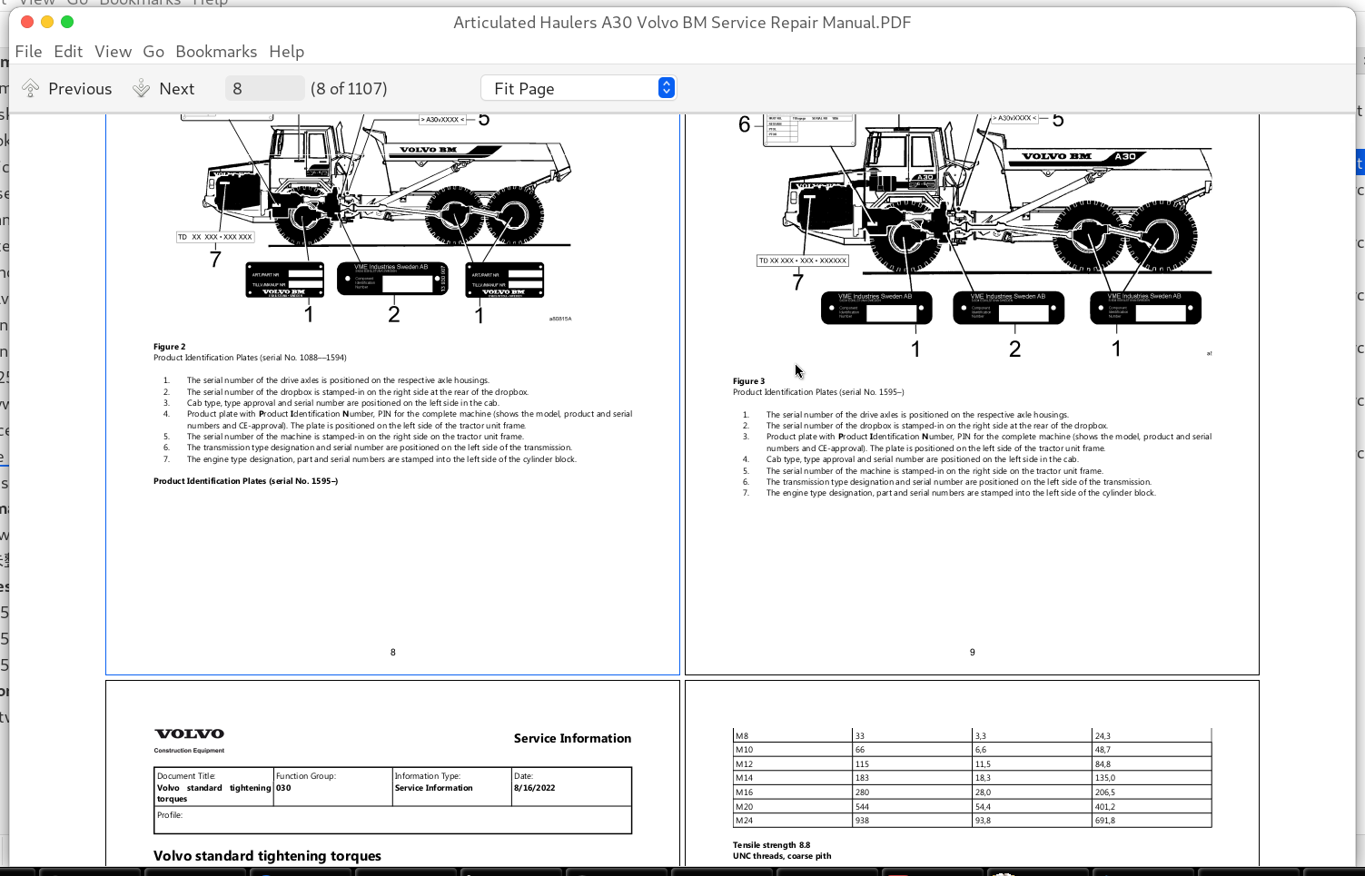
Product Identification Plates................7
Volvo standard tightening torques................10
08 - TOOL................12
E-tools................13
Filling and recycling station (part No. 11 666 070)................36
Filling and recycling station FRS-10GS (part No. 981 2443)................38
Multi-pin breaker box (part No. 11 668 001)................40
Multi-pin breaker box (part No. 11 668 002)................42
Weighing scales 981 2444................44
1 - STANDARD PARTS; SERVICE................46
10 - GENERAL................47
Recovering................48
Towing machine................50
17 - SERVICE................52
Brake fluid; changing................53
Cleanliness; brake and hydraulic systems................55
Electric welding................56
Trouble-shooting-................57
19 - GENERAL................58
Recovering................59
Towing machine................61
Air conditioning................63
Batteries................65
Before operating................67
Charging batteries................69
Climate control system................70
Emergency exit................71
Fluor rubber................72
General-1936................73
Measures to prevent fire................74
Risks in connection with polymer materials-1849................77
Risks in connection with polymer materials................78
Rules when servicing................79
Tyre................84
When lifting the machine................85
When the engine is running................89
When the service has been completed; or if the machine is laid up for a longer period................90
When there is risk of overturning................91
When transporting the machine................92
2 - ENGINE WITH MOUNTING AND EQUIPMENT................95
20 - GENERAL................96
Description ................97
Diagnosis using Service Display Unit................98
Trouble-shooting................99
21 - ENGINE................100
Compression test; warm engine................101
Engine and transmission; installing................104
Engine and transmission; removing................107
Engine; installing................114
Engine; removing................118
TD102KF (serial No.–1227)................125
TD102KFE (low-emission engine)–equipment................126
TD102KH (serial No. 1228–).................127
Tightening torques ................128
Weights................129
General ................130
Valves; adjusting................131
Flywheel housing and power take-off................133
Crankshaft; replacing front oil seal................136
Crankshaft; replacing rear oil seal................141
Flywheel housing with power take-off; removing and installing; engine removed................146
Tightening torques-................151
Tightening torques ................152
22 - LUBRICATING SYSTEM................154
Capacities-................155
Description-................156
General-................157
Description-0036................158
Description-5957................159
23 - FUEL SYSTEM................160
Description-5858................161
Feed pressure................163
Feed pressure; checking................165
General-5733................166
Capacities-5712................167
Discs on pump shaft; checking-5634................168
Discs on pump shaft; checking................170
Engine speed; method for checking................172
Engine speed; method for checking with Service Display Unit (serial No. 1706Engine speed; method for checking with Service Display Unit (serial No. 1706–))................174
Injection angle (injection timing); checking and adjusting................175
Injection pump TD102KF (serial No. –1227)................179
Injection pump TD102KFE (low-emission engine)................180
Injection pump TD102KH (serial No. 1228–)................181
Low and high idling speeds; checking and adjusting................182
Low and high idling speeds; checking and adjusting with Service Display Unit................186
Stall speed; checking................189
Stall speed; checking with Service Display Unit................191
General-5220................193
Injectors; replacing................194
25 - INLET & EXHAUST SYSTEM................197
Description of function................198
General-5042................201
General-5004................202
26 - COOLING SYSTEM................203
Capacities................204
Description-4905................205
TD102KF (serial No. –1227)................207
TD102KFE (low-emission engine)................208
TD102KH (serial No. 1228–)................209
Coolant filter; replacing................210
Coolant; changing................212
Radiator; adjusting................214
Radiator; replacing................216
Coolant pump; removed; reconditioning (serial No. –1308)................219
Coolant pump; removed; reconditioning (serial No. 1309–)................226
Coolant pump; replacing................234
General-4432................236
Cooling fan; trouble-shooting hydraulic system-4410................237
Cooling fan; trouble-shooting hydraulic system................240
General-4336................243
Hydraulic motor and hydraulic pump for fan; checking and adjusting................244
Hydraulic motor for fan................249
Hydraulic motor for fan; or alternatively hydraulic pump for fan; checking internal leakage................253
Hydraulic motor for fan; reconditioning................255
Thermostat valve (removed); reconditioning................263
Thermostat valve; checking function................265
Thermostat valve; Description................267
Tightening torques................271
3 - ELECTRICAL; WARNING; INFORMATION; INSTRUMENTS................272
30 - GENERAL................273
Description................274
General-................276
Special instructions for working on electrical systems................277
31 - BATTERY................278
General-................279
32 - ALTERNATOR; CHARGE REGULATOR................280
Alternator; replacing................281
General ................283
Testing charging on machine................284
General-3623................286
33 - STARTING SYSTEM................287
General-................288
Starting system................289
35 - LIGHTING................291
General................292
Headlights; adjusting................293
Headlights; replacing lamp................294
37 - CABLE; FUSE; RELAY................295
Circuit 1-................296
Circuit 1................300
Circuit 2-................304
Circuit 2................310
Circuit 3-................314
Circuit 3................318
Circuit 4-................322
Circuit 4................329
Circuit 5-................334
Circuit 5................341
Circuit 6-................348
Circuit 6................352
Circuit 7-................359
Circuit 7................363
Circuit 8-................367
Circuit 8................371
Circuit 9................375
Circuit 10................379
Codes in wiring diagrams................383
Codes in wiring diagrams (1706–)................390
Electrical symbols................397
Explanations of wiring diagrams (lead and component marking................402
Electrical distribution box in cab................404
Fuses................405
Left electrical distribution box (serial No. 1706–)................406
Other fuses and relays................408
Other fuses and relays (serial no. 1706–)................409
Relays and fuses (serial No. –1705)................411
Right electrical distribution box (serial no. –1705)................413
Right electrical distribution box (serial no. 1706–)................414
38 - INSTRUMENT; SENSOR; WARNING & INFORMATION SYSTEM................415
Instrument cluster................416
Other controls (serial No. –1705)................418
Other controls (serial No. 1706–)................420
Right instrument panel (serial No. –1705)................422
Right instrument panel (serial No. 1706–)................423
Contronic Display Unit (serial No. 1706–)................425
Contronic Display Unit; overview................427
Contronic Service Display Unit................428
Contronic Service Display Unit; overview................430
Description of steps (functions) (serial No. –1705)................432
Diagnosis with the aid of display unit (serial No. –1705)................437
Diagnosis with the aid of Service Display Unit (serial No. 1706–)................441
Error codes................444
Information on the display unit................446
Information on the Service Display Unit................452
Operator Information................463
4 - POWER TRANSMISSION................464
40 - GENERAL................465
Description................466
Trouble-shooting (serial No. –1705)................468
Trouble-shooting (serial No. 1706–)................469
41 - CLUTCH; TORQUE CONVERTER................470
General................471
Tightening torques................472
Weights................473
42 - TRANSMISSION; HYDRAULIC CONTROL................474
Component description (serial No. –1705................476
Component description (serial No. 1706–)................478
Gearshifting control (serial No. –1705)................480
Gearshifting control (serial No. 1706–)................481
Cause and action-................482
Cause and action................499
Checking main; torque converter and lubricating oil pressures................509
Checking modulator valve; retarder and lockup................513
Checking pressure in clutches and brakes................514
Connector EH................515
Diagnosis using Service Display Unit (serial No. 1706–)................516
Diagnosis with display unit (serial No. –1705)................519
Hydraulic diagram; transmission................521
Measuring resistance in connector................524
Measuring resistance in connector EH (with multi-pin breaker box 11 668 001)................527
Measuring resistance in connector EH (with multi-pin breaker box 11 668 002)................531
Measuring resistance in sensor for retarder temperature (SE13)................535
Measuring resistance SE3; SE4 and SE86................536
Missing signal from both engine speed sensor (SE3) and travelling speed sensor (SE4)................538
Missing signal from engine speed sensor (SE3)................539
Other error causes (serial No. –1705)................540
Other error causes (serial No. 1706–)................543
Pin numbering in EA (serial No.–1705)................546
Pin numbering in EA (serial No. 1706–)................547
Pin numbering in EB (serial No.–1705)................548
Pin numbering in EB (serial No. 1706–................549
Pin numbering in EC (serial No. 1706–)................550
Pressure regulator for retarder; checking and adjusting (serial No. –1705)................551
Pressure regulator for retarder; checking and adjusting (serial No. 1706–)................554
Replacing control system for automatic gear shifting in transmission................556
Replacing seal; output shaft on transmission................559
Replacing seal; retarder valve................562
Table for oil pressure; transmission................564
Transmission PT1661; drawing................565
Transmission; installing–downward................568
Transmission; removing and installing–upward through doorway-0810................575
Transmission; removing and installing–upward through doorway................583
Transmission; removing–downward................587
Turbine speed sensor (SE86); replacing................597
Weights................600
43 - GEARBOX................601
Capacities ................602
Clutches; brakes and solenoids................603
General-................606
Tightening torques-0456................607
Weights-................608
Capacities................609
Checking and adjusting longitudinal differential lock; from underneath................610
Dropbox (6x6); drawing................614
Dropbox; installing................616
Dropbox; removing................619
Front output shaft on dropbox; replacing seal................624
General................627
Input shaft on dropbox; replacing seal................628
Rear output shaft on dropbox; replacing seal................630
Tightening torques................631
Weights................635
45 - PROPELLER SHAFT................636
Tightening torques................637
Front output propeller shaft on dropbox; replacing................638
Input propeller shaft on dropbox; replacing................640
Intermediate shaft (in frame joint) and_or bearings; replacing................642
Propeller shaft for front bogie axle; replacing................652
Propeller shaft for rear bogie axle; replacing................654
Propeller shaft in steering joint; replacing................656
46 - FRONT AXLE; REAR AXLE................657
Differential carrier assembly and differential lock; drawing................658
Dog clutch for 6-wheel drive (6x6); checking and adjusting................661
Drive axles................665
Dropbox 6x6 and differential; replacing................666
Hub reduction gear; AH63 I; J; K; drawing................674
Output shaft on front bogie axle; replacing seals and bearing................675
Tightening torques-3722................680
Weights-3656................681
Capacities-3618................682
General-3552................683
Hub reduction gear; replacing seals................684
Capacities-................691
General-................692
Capacities ................693
General ................694
Transverse differential lock _ drive axle; checking and adjusting................695
48 - POWER TAKE OFF................699
General ................700
Flywheel housing with power take-off; removed; reconditioning................701
5 - BRAKE................712
50 - GENERAL................713
Description ................714
Service brakes................715
51 - WHEEL BRAKE................716
Brake disc for service brakes; checking................717
Brake pads for service brakes; checking................719
General-................721
Tightening torques-................722
Brake caliper; replacing................723
Brake disc for service brakes; replacing................727
Brake pads for service brakes; replacing................735
Brake caliper; reconditioning................741
52 - HYDRAULIC BRAKE SYSTEM................744
Bromssystem; luftning................745
Capacities ................747
Foot brake valve................748
Foot brake valve; replacing................751
55 - PARKING BRAKE................753
Automatic adjusting lever................754
Description- ................756
General ................757
Parking brake; replacing brake caliper................758
Spring brake cylinder................762
Spring brake cylinder; replacing................764
Tightening torques ................766
Weights ................767
Parking brake valve; reconditioning (removed)................768
Parking brake caliper; removed; reconditioning................771
Parking brake; replacing brake disc................773
Parking brake; replacing brake pads................778
Spring brake cylinder; removed; reconditioning................782
Description-................785
56 - COMPRESSED-AIR BRAKE................788
Air-hydraulic brake cylinder................789
Compressed-air diagram................790
Description- ................793
Air compressor................794
Air compressor; Dropbox; removing and installing................797
Air compressor; general repair instructions................799
Anti-freeze reservoir................801
General ................802
Pressure regulator................803
Pressure regulator; cut-out and cut-in pressure; checking and adjusting................806
Pressure regulator; removed; lubrication................807
Tightening torques ................810
Valve block for differential locks and 6-wheel drive................811
General ................812
Safety valve; wet reservoir................813
4-way pressure retaining valve................814
Foot brake valve; removed; reconditioning................816
General- ................822
Relay valve................823
59 - MISCELLANEOUS................825
General-................826
6 - STEERING................827
64 - STEERING................828
Description ................829
Description-................831
General..................836
General ................837
Steering gear; replacing................838
Steering linkage; checking and adjusting................841
Tightening torques ................848
Damping cylinder; checking preload................850
Damping cylinder; drawing................852
Damping cylinder; replacing seals................853
General-................855
Max. oil pressure; hydraulic system (steering and tipping); checking and adjusting................856
Steering cylinder; drawing................860
Steering cylinder; replacing................862
Steering cylinder; replacing seals................866
Steering valve complete with connections................872
Steering valve; removed; reconditioning................877
Steering valve; removing and installing................882
Tightening torques-................884
Weights-................885
Secondary steering; adjusting working pressure and stand-by pressure................886
7 - FRAME; SPRINGS; DAMPING; AXLE SUSPENSION; WHEEL_TRACK UNIT................889
71 - FRAME................890
Dump body joint; replacing tipping bearings................891
Dump body; adjusting against frame ................895
Dump body; adjusting against frame................897
Description ................899
Tightening torques ................901
Trailer unit frame; checking measurements................904
72 - SUSPENSION................907
Description ................908
Rubber element; tractor unit; replacing................909
74 - FRAME LINK................912
Frame joint; checking and adjusting clearance................913
Frame joint; removed; replacing wear rings on hitch................916
Frame joint; replacing hitch................920
Parting and assembling tractor and trailer units................938
Frame joint; removed; replacing bearings................945
Steering joint bearings; checking clearance................946
Steering joint; replacing bearings and bearing pins................948
Tightening torques-................963
75 - AXLE SUSPENSION................965
A-stay tractor unit; replacing link bearing................966
Cross stay link bearing (rubber bearing); replacing................970
Front A-stay link bearing bracket; adjusting................972
Front A-stay link bearing; (rubber bearing); replacing................974
Front or rear cross stay; adjusting (trailer unit)................979
Rear A-stay link bearing bracket; adjusting................980
Rear A-stay link bearing; (rubber bearing); replacing................981
Rubber bearing; bogie member; replacing (one side)................986
Rubber element; bogie member; replacing (one side)................990
77 - WHEELS; TRACKS; TYRE; HUB; DRUM................992
Weights ................993
General-................994
Tightening torques-................995
8 - MACHINERY HOUSE; CAB; EXTERIOR TRIM PARTS ANYWHERE................996
82 - ENGINE HOOD; MUDGUARD; FOOT STEP................997
Weights-................998
84 - TRIM PART; OUTSIDE; GLASS; SEALING MOULDING................999
Window pane; replacing................1000
85 - CAB INTERIOR; UPHOLSTERY................1002
Air spring for operator seat; replacing................1003
Operator seat (serial No. –1183)................1005
Operator seat; height adjustment of attachment................1007
Operator seat; maintenance advice................1008
Operator seat; mechanically sprung (serial No. 1184–)................1009
Seat with air suspension................1010
87 - AIR CONDITIONING UNIT................1011
Description................1012
Wiring diagram (sub diagram); Cab fan_Air conditioning................1013
Fan motor; replacing................1014
Fan motor; replacing resistors................1015
Heater radiator; replacing................1018
Hot water valve; replacing................1020
Air conditioning; checking function................1023
Description of function................1025
Refrigerant R134a; emptying (using filling and recycling station FRS-10GS part No. 981 2443)................1027
Refrigerant R134a; emptying (with filling and recycling station part No. 11 666 070)................1031
Refrigerant R134a; vacuum-pumping including filling (using filling and recycling station part No. 11 666 070)................1036
Refrigerant R134a; vacuum-pumping including filling (with filling and recycling station FRS-10GS part No. 981 2443)................1042
9 - HYDRAULIC SYSTEM; DIGGING_HANDLING_GRADING EQUIPMENT; MISCELLANEOUS................1046
91 - WORKING HYDRAULIC; SERVO HYDRAULICS................1047
Capacities-................1048
Diagnosis using service display unit (serial No. 1706–)................1049
Hydraulic diagram; complete................1051
Hydraulic system; air bleeding................1054
Hydraulsystem; Description................1055
Tipping system; description................1057
Capacities................1058
General ................1059
Non-return valve block; left................1060
Non-return valve block; right................1061
General................1063
Hydraulic pump; description................1064
Hydraulic pump; ground-dependent; replacing................1066
Hydraulic pumps for steering and tipping systems; checking internal leakage................1068
Stand-by pressure; LS (load-sensing) line disconnected and connected................1071
Tightening torques-3120................1075
Weights................1076
95 - LOAD CARRIER................1077
General................1078
Installing piston rod seals................1079
Tightening torques................1081
Tipping control; adjusting................1082
Tipping cylinder................1083
Tipping cylinder; replacing................1084
Tipping cylinders; replacing piston rod seals (with the aid of 999 3579 and 999 3579B)................1092
Tipping valve................1097
Tipping valve; changing seals (removed)................1100
Tipping valve; removing and installing................1102
Tipping valve; replacing cable control................1104
Weight................1107
Articulated Haulers A30 Volvo BM Service Repair Manual
![]()