
Articulated Haulers A30C Volvo / A30C Volvo BM Service Repair Manual
Articulated Haulers A30C Volvo / A30C Volvo BM Service Repair Manual
Complete official service manual with electrical wiring diagrams for Articulated Haulers A30C Volvo / A30C Volvo BM, with all the shop information to maintain, diagnose, repair, rebuild like professional mechanics.
Articulated Haulers A30C Volvo / A30C Volvo BM workshop service & repair manual includes:
* Numbered table of contents easy to use so that you can find the information you need fast.
* Detailed sub-steps expand on repair procedure information
* Numbered instructions guide you through every repair procedure step by step.
* Troubleshooting and electrical service procedures are combined with detailed wiring diagrams for ease of use.
* Notes, cautions and warnings throughout each chapter pinpoint critical information.
* Bold figure number help you quickly match illustrations with instructions.
* Detailed illustrations, drawings and photos guide you through every procedure.
* Enlarged inset helps you identify and examine parts in detail.
MAIN SECTIONS
0 - GENERAL
1 - STANDARD PARTS, SERVICE
2 - ENGINE WITH MOUNTING AND EQUIPMENT
3 - ELEC. SYSTEM; WARNING SYSTEM; INFORMATION SYSTEM; INSTRUMENTS
4 - POWER TRANSMISSION
5 - BRAKE
6 - STEERING
7 - FRAME; SPRINGS; DAMPING; AXLE SUSPENSION; WHEEL_TRACK UNIT
8 - MACHINERY HOUSE; CAB; EXTERIOR TRIM PARTS ANYWHERE
9 - HYDRAULIC SYSTEM; DIGGING_HANDLING_GRADING EQUIPM.; MISC EQUIPM
File Format: PDF (bookmarked, Searchable, Printable, high quality)
Language: English
Pages: 947
0 - GENERAL
00 - DESCRIPTION; COMPLETE MACHINE
Description.pdf
03 - SPECIFICATIONS
Brake and compressed-air systems.pdf
Capacities.pdf
Cooling system.pdf
Dimensional drawing.pdf
Dimensions with tyres 23.5 R-25.pdf
Electrical system.pdf
Engine specifications.pdf
Filter replacement, intervals.pdf
Fuel system.pdf
Hydraulic system.pdf
Oil and fluid change, intervals.pdf
Power transmission.pdf
Product identification plates.pdf
Recommended lubricants.pdf
Steering system.pdf
Tightening torques.pdf
Volvo standard tightening torques.pdf
Weights, (approx.).pdf
07 - STANDARD TIME
Time Guide.pdf
08 - TOOL
Drawings of E-tools which can.pdf
Tools for the drive train.pdf
1 - STANDARD PARTS, SERVICE
16 - LUBRICANT; FUEL; OTHER FLUID
Brake system, changing brake fluid.pdf
Filter replacement, intervals.pdf
Hydraulic oil, sampling.pdf
Oil and fluid change, intervals.pdf
Recommended lubricants.pdf
17 - SERVICE
Charging batteries.pdf
Cleanliness, brake and hydraulic systems.pdf
Electric welding.pdf
Recovering.pdf
Refrigerant for air conditioning.pdf
Towing machine.pdf
Trouble-shooting-[4109].pdf
2 - ENGINE WITH MOUNTING AND EQUIPMENT
20 - GENERAL
Capacities-[4028].pdf
Description-[4008].pdf
Diagnosis using Service Display Unit-[3953].pdf
General specifications-[3933].pdf
Tightening torques-[3919].pdf
Trouble-shooting-[3902].pdf
Weights, (approx.)-.pdf
21 - ENGINE
Compression test, warm engine.pdf
Engine and transmission, installing.pdf
Engine and transmission, removing.pdf
Engine, installing.pdf
Engine, removing.pdf
Valve mechanism.pdf
Valves, adjusting.pdf
22 - LUBRICATING SYSTEM
Description-[2934].pdf
General specifications-[2910].pdf
23 - FUEL SYSTEM
Feed pump, checking feed pressure.pdf
Feed pump.pdf
Fuel system, air bleeding.pdf
Injection angle (injection timing) B.T.D.C., checking and adjusting.pdf
Injection pump.pdf
Injection timing adjuster, checking.pdf
Injection timing adjuster.pdf
Injectors.pdf
Injectors, replacing all.pdf
Low and high idling speed, checking and adjusting using service dispaly unit.pdf
Low-emission engines.pdf
Stall speed, checking using Service Display Unit.pdf
25 - INLET & EXHAUST SYSTEM
Description of function.pdf
Sensor exhaust retarder, adjusting.pdf
Sensor, exhaust retarder, replacing.pdf
26 - COOLING SYSTEM
Coolant, changing.pdf
Coolant pump removed, reconditioning.pdf
Cooling fan motor, adjusting speed.pdf
Description.pdf
Fan motor, changing piston rings.pdf
Fan motor, checking working pressure.pdf
General specifications.pdf
Radiator, adjusting.pdf
Radiator, replacing.pdf
Thermostat valve.pdf
Thermostat valve removed, checking.pdf
3 - ELECTRICAL; WARNING; INFORMATION; INSTRUMENTS
30 - GENERAL
Diagnosis with the aid of Service Display Unit.pdf
General-[1443].pdf
Trouble-shooting.pdf
31 - BATTERY
Charging batteries.pdf
Specifications-[1341].pdf
32 - ALTERNATOR; CHARGE REGULATOR
Alternator, replacing.pdf
Specifications-[1235].pdf
Specifications-[1249].pdf
33 - STARTING SYSTEM
Specifications-[1126].pdf
Specifications-[1155].pdf
Starter motor, replacing.pdf
35 - LIGHTING
Headlights, adjusting.pdf
Headlights, replacing light bulb.pdf
Specifications-[0841].pdf
Specifications-[0917].pdf
Specifications-[0931].pdf
Specifications-[0956].pdf
36 - OTHER ELECTRICAL EQUIPMENT
Specifications.pdf
37 - CABLE; FUSE; RELAY
Audible signals.pdf
Circuit 10.pdf
Circuit 10 .pdf
Circuit 11.pdf
Circuit 11 .pdf
Circuit 12.pdf
Circuit 12 .pdf
Circuit 1 (serial No. –2900).pdf
Circuit 1 (serial No. 2901–, US 60001–).pdf
Circuit 2-[0610].pdf
Circuit 2.pdf
Circuit 3.pdf
Circuit 3 .pdf
Circuit 4.pdf
Circuit 4 .pdf
Circuit 5 (continued) .pdf
Circuit 5 (continued).pdf
Circuit 5.pdf
Circuit 5 .pdf
Circuit 6 (continued) .pdf
Circuit 6 (continued).pdf
Circuit 6.pdf
Circuit 6 .pdf
Circuit 7.pdf
Circuit 7 .pdf
Circuit 8.pdf
Circuit 8 .pdf
Circuit 9.pdf
Circuit 9 .pdf
Codes in wiring diagrams.pdf
Connectors, illustrations.pdf
Connectors, leads (serial No. –2900).pdf
Connectors, leads (serial No. 2901–,).pdf
Control lamps.pdf
Electrical motors.pdf
Electrical symbols.pdf
Explanations of wiring diagrams.pdf
Fuses.pdf
General.pdf
Heating elements.pdf
Instruments.pdf
Lamps.pdf
Left electrical distribution box.pdf
Other fuses and relays (serial No. –2900).pdf
Other fuses and relays (serial No. 2901–,).pdf
Relays.pdf
Right electrical distribution box.pdf
Sensors.pdf
Solenoid valves.pdf
Specifications.pdf
Switches.pdf
38 - INSTRUMENT; SENSOR; WARNING & INFORMATION SYSTEM
Contronic, description of function.pdf
Contronic Display Unit, overview.pdf
Contronic Service Display Unit, overview.pdf
Display unit.pdf
Function groups.pdf
General.pdf
Instrument cluster.pdf
Other controls (serial No. –2900).pdf
Other controls (serial No. 2901–,).pdf
Programming instructions.pdf
Right instrument panel (serial No. –2900).pdf
Right instrument panel (serial No. 2901–,.pdf
Service Display Unit menus.pdf
Service display unit.pdf
Speedometer electrical, serial No. 2601–3222, US 60005–60172.pdf
Speedometer, electronic.pdf
4 - POWER TRANSMISSION
40 - GENERAL
Clutches, brakes and solenoids.pdf
Component descriptions.pdf
Description.pdf
Diagnosis using Service Display Unit.pdf
Error messages.pdf
Gearshifting control (serial No. –2900).pdf
Gearshifting control (serial No. 2901–,.pdf
Missing signal from both engine speed sensor (SE3) and travelling speed sensor (SE4).pdf
Missing signal from engine speed sensor (SE3).pdf
Other error causes.pdf
Transmission, clutches and brakes.pdf
Trouble-shooting diagram.pdf
41 - CLUTCH; TORQUE CONVERTER
Tightening torques.pdf
Weights, approx.pdf
42 - TRANSMISSION; HYDRAULIC CONTROL
Capacities.pdf
Checking main, torque converter.pdf
Checking modulator valves, retarder and lockup.pdf
Checking pressure in clutches and brakes.pdf
Connector EH.pdf
General.pdf
Measuring resistance in cable harness.pdf
Measuring resistance in SE3, SE4 and SE86.pdf
Measuring resistance in sensor for.pdf
Measuring resistance in solenoids.pdf
Multi-pin breaker box.pdf
Pin numbering in EA.pdf
Pin numbering in EB.pdf
Pin numbering in EC.pdf
Retarder, description of function.pdf
Retarder valve, replacing seal.pdf
Seal for rear output shaft, replacing.pdf
Specifications.pdf
Tightening torques.pdf
Transmission, installing – downward.pdf
Transmission, installing – upward through doorway.pdf
Transmission, removing – downward.pdf
Transmission, removing – upward through doorway.pdf
Transmission retarder valve, adjusting air pressure.pdf
Turbine speed sensor, replacing.pdf
Weights, (approx.)..pdf
43 - GEARBOX
Capacities.pdf
Differential lock, longitudinal, adjusting engagement.pdf
Dropbox, installing.pdf
Dropbox, removing.pdf
Dropbox, replacing seal for front output shaft.pdf
Dropbox, replacing seal for input shaft.pdf
Dropbox, replacing seal for rear output shaft.pdf
General.pdf
Specifications.pdf
Weights, approx..pdf
45 - PROPELLER SHAFT
Propeller shaft between transmission.pdf
Propeller shaft for front bogie axle, replacing.pdf
Propeller shaft for rear bogie axle, replacing.pdf
Propeller shaft, front output shaft.pdf
Propeller shaft in steering joint, replacing.pdf
46 - FRONT AXLE; REAR AXLE
Capacities..pdf
Capacities.pdf
Differential lock, transverse,.pdf
Dog clutch 6x6, checking and adjusting.pdf
Drive axles.pdf
Hub, replacing seals (one side).pdf
Specifications.pdf
Tightening torques.pdf
Weights, (approx.)..pdf
Weights, approx.-.pdf
48 - POWER TAKE OFF
Specifications.pdf
49 - MISCELLANEOUS
Transmission, hydraulic diagram,.pdf
Transmission PT1663.pdf
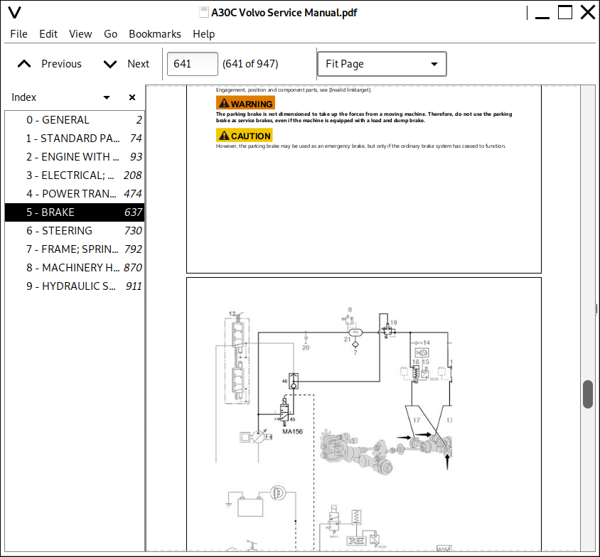
5 - BRAKE
50 - GENERAL
Capacities.pdf
Introduction.pdf
Specifications.pdf
51 - WHEEL BRAKE
Brake caliper, replacing.pdf
Brake disc for service brakes, checking.pdf
Brake discs, replacing (one wheel).pdf
Brake pads for service brakes.pdf
Brake pads, replacing.pdf
Specifications .pdf
Specifications.pdf
Tightening torques.pdf
52 - HYDRAULIC BRAKE SYSTEM
Brake system, air bleeding.pdf
Description (serial No. 2901–, US 60001–).pdf
Foot brake valve.pdf
Relay valve.pdf
55 - PARKING BRAKE
Automatic adjusting lever.pdf
Description.pdf
Parking brake caliper, removed, reconditioning.pdf
Parking brake, replacing brake disc.pdf
Parking brake, replacing brake pads.pdf
Parking brake valve (Hand control).pdf
Parking brake valve.pdf
Parking brake valve, reconditioning (removed).pdf
Specifications.pdf
Spring brake cylinder.pdf
Spring brake cylinder removed, reconditioning.pdf
Tightening torques.pdf
Weights, approx.pdf
56 - COMPRESSED-AIR BRAKE
4-way pressure retaining valve.pdf
Air compressor.pdf
Anti-freeze reservoir.pdf
Compressor, replacing.pdf
Cut-out and cut-in pressure, checking and adjusting.pdf
Description.pdf
General repair instructions, compressor.pdf
Pressure regulator.pdf
Safety valve, wet reservoir.pdf
Specifications.pdf
Tightening torques.pdf
59 - MISCELLANEOUS
Compressed-air system, item list.pdf
Compressed-air system, item list (serial No..pdf
Specifications.pdf
6 - STEERING
60 - GENERAL
Description .pdf
64 - STEERING
Adjusting working pressure and stand-by pressure.pdf
Damping cylinder, checking preload.pdf
Damping cylinder, replacing seals.pdf
Description.pdf
Specifications .pdf
Specifications-.pdf
Specifications.pdf
Steering cylinder, changing seals in machine.pdf
Steering cylinder, replacing (right side).pdf
Steering gear, checking and adjusting.pdf
Steering gear, replacing.pdf
Steering linkage, checking and adjusting.pdf
Steering linkage, replacing roller bearing in.pdf
Steering system, checking working pressure.pdf
Steering valve complete with connections.pdf
Steering valve, removed, reconditioning.pdf
Steering valve, removing and installing.pdf
Steering valve spool end float, checking and adjusting.pdf
Weights, approx..pdf
7 - FRAME; SPRINGS; DAMPING; AXLE SUSPENSION; WHEEL_TRACK UNIT
70 - GENERAL
Description.pdf
71 - FRAME
Dump body, adjusting against frame.pdf
Dump body joint, replacing tipping bearings.pdf
Tightening torques.pdf
Trailer unit frame, checking measurements.pdf
Weights, approx
72 - SUSPENSION
General.pdf
Removing and installing.pdf
74 - FRAME LINK
Frame joint, checking and adjusting clearance.pdf
Frame joint, replacing bearings.pdf
Frame joint, replacing bushing.pdf
Frame joint, separating and assembling.pdf
Steering joint, adjusting clearance.pdf
Steering joint, replacing bearings.pdf
Tightening torques.pdf
75 - AXLE SUSPENSION
Bogie member, replacing rubber bearing, one side.pdf
Bogie, replacing all rubber elements, both sides.pdf
Cross stay, checking and adjusting.pdf
Cross stay link bearing (rubber bearing), replacing.pdf
Front A-stay link bearing, (rubber bearing), replacing.pdf
Rear A-stay link bearing, (rubber bearing), replacing.pdf
Replacing link bearing (rubber bearing) front axle.pdf
8 - MACHINERY HOUSE; CAB; EXTERIOR TRIM PARTS ANYWHERE
81 - CAB, NAKED; CANOPY
Filter replacement, intervals.pdf
Weights, approx.pdf
82 - ENGINE HOOD; MUDGUARD; FOOT STEP
Weights, approx
84 - TRIM PART; OUTSIDE; GLASS; SEALING MOULDING
Replacing.pdf
85 - CAB INTERIOR; UPHOLSTERY
Adjusting possibilities.pdf
Air spring for operator seat, replacing.pdf
If the back-rest is binding or has excessive play.pdf
Maintenance advice.pdf
Operator seat, height adjustment of attachment.pdf
87 - AIR CONDITIONING UNIT
Air conditioning, checking function.pdf
Air conditioning, description of function.pdf
Fan motor, replacing.pdf
Filling and recycling station FRS-10GS.pdf
Heat control valve, replacing.pdf
Heater radiator, replacing.pdf
Refrigerant, emptying.pdf
Refrigerant R134a, vacuum-pumping including filling.pdf
Safety instructions.pdf
88 - INTERIOR EQUIPMENT
Protection against electromagnetic interference.pdf
9 - HYDRAULIC SYSTEM; DIGGING_HANDLING_GRADING EQUIPMENT; MISCELLANEOUS
90 - GENERAL
Diagnosis using service display unit.pdf
Hydraulic pump.pdf
Non-return valve block, right.pdf
Tipping system, description.pdf
Trouble-shooting.pdf
91 - WORKING HYDRAULIC; SERVO HYDRAULICS
Capacities.pdf
Hydraulic pumps, for steering and.pdf
Hydraulic system, air bleeding.pdf
Oil pump, checking and adjusting.pdf
Oil pump, ground-dependent, replacing.pdf
Specifications.pdf
Weights, approx
95 - LOAD CARRIER
Cooling fan drive, description.pdf
Specifications.pdf
Tipping valve, removing and installing.pdf
Weights, approx
99 - MISCELLANEOUS
Hydraulic diagram, complete.pdf
Hydraulic diagram.pdf
![]()