
Articulated Haulers A25C Volvo / A25C Volvo BM / A25C Volvo 4x4 / A25C Volvo 4x4 BM Service Repair Manual

Complete repair service manual with electrical wiring diagrams for Articulated Haulers A25C Volvo / A25C Volvo BM / A25C Volvo 4x4 / A25C Volvo 4x4 BM, with technical information to maintain, diagnose, repair, and service like professional mechanics.
Articulated Haulers A25C Volvo / A25C Volvo BM / A25C Volvo 4x4 / A25C Volvo 4x4 BM workshop service & repair manual includes:
* Numbered table of contents easy to use so that you can find the information you need fast.
* Detailed sub-steps expand on repair procedure information
* Numbered instructions guide you through every repair procedure step by step.
* Troubleshooting and electrical service procedures are combined with detailed wiring diagrams for ease of use.
* Notes, cautions and warnings throughout each chapter pinpoint critical information.
* Bold figure number help you quickly match illustrations with instructions.
* Detailed illustrations, drawings and photos guide you through every procedure.
* Enlarged inset helps you identify and examine parts in detail.
MAIN SECTIONS
0 - GENERAL
1 - STANDARD PARTS, SERVICE
2 - ENGINE WITH MOUNTING AND EQUIPMENT
3 - ELEC. SYSTEM; WARNING SYSTEM; INFORMATION SYSTEM; INSTRUMENTS
4 - POWER TRANSMISSION
5 - BRAKE
6 - STEERING
7 - FRAME; SPRINGS; DAMPING; AXLE SUSPENSION; WHEEL_TRACK UNIT
8 - MACHINERY HOUSE; CAB; EXTERIOR TRIM PARTS ANYWHERE
9 - HYDRAULIC SYSTEM; DIGGING_HANDLING_GRADING EQUIPM.; MISC EQUIPM
PRODUCT DETAILS:
Pages: 1,170
File Format: PDF (Windows & Mac & Linux)
Language: English
...
TABLE OF CONTENTS
0 - Foreword.......2
0 - GENERAL.......3
00 - DESCRIPTION; COMPLETE MACHINE.......4
Description-[3028].......4
Product identification plates.......5
03 - SPECIFICATIONS.......6
Brakes.......6
Electrical system.......9
Engine.......12
Hydraulic system.......15
Power transmission-.......17
Specifications, capacities-.......21
Specifications, change intervals.......22
Specifications, dimensions.......23
Specifications, tightening torques].......25
Specifications, weights .......36
Steering system.......38
Volvo standard tightening torques.......39
07 - STANDARD TIME.......41
Time Guide.......41
08 - TOOL.......50
Drawings of E-tools that can be made in your own workshop.......50
Recycling station FRS-10GS.......63
Special tools for the drivetrain.......65
1 - STANDARD PARTS, SERVICE.......69
16 - LUBRICANT; FUEL; OTHER FLUID.......70
Brake system, changing brake fluid.......70
Recommended lubricants.......72
17 - SERVICE.......74
Cleanliness, hydraulic systems.......74
Electric welding.......75
Repairs of hydraulic systems.......76
Towing.......77
2 - ENGINE WITH MOUNTING AND EQUIPMENT.......80
21 - ENGINE.......81
Compression check, engine at operating temperature.......81
Description.......84
Engine and transmission, mounting.......85
Engine and transmission, removing.......89
Engine, mounting.......98
Engine, removing.......102
Specifications, capacities-[1855].......110
Specifications, general-[1633].......111
Specifications, general-[1810].......112
Specifications, tightening torques-[1423].......113
Specifications, tightening torques-[1451].......116
Specifications, tightening torques-[1536].......117
Specifications, tightening torques-[1550].......118
Specifications, tightening torques-[1657].......119
Specifications, tightening torques-[1721].......120
Specifications, tightening torques-[1750].......121
Specifications, tightening torques-[1841].......122
Specifications, weights-[1823].......124
Valves, adjusting.......125
22 - LUBRICATING SYSTEM.......127
Lubrication oil pressure, checking.......127
Specifications, general-.......129
Specifications, general-[1304].......130
23 - FUEL SYSTEM.......131
Automatic timing adjuster (alpha adjuster).......131
Automatic timing adjuster, checking.......132
Fuel feed pump, checking feed pressure.......138
Fuel injection pump, changing incl. setting injection timing.......140
Fuel system, bleeding.......146
Idle speed, checking and adjusting.......148
Injection timing TDC, checking and adjusting.......150
Injection timing, checking.......155
Injectors, changing all.......159
Low and high idle speed, checking and adjusting with service display unit.......163
Low emission engines.......166
Specifications, capacities-[1054].......168
Specifications, general-[0643].......169
Specifications, general-[0814].......170
Specifications, general-[1118].......171
Specifications, tightening torques-[0657].......172
Specifications, tightening torques-[0828].......173
Stall speed, checking with service display unit.......174
Stall speed, checking.......176
25 - INLET & EXHAUST SYSTEM.......177
Specifications, general-[0357].......177
Specifications, general-[0422].......178
Specifications, tightening torques-[0446].......179
26 - COOLING SYSTEM.......180
Coolant filter, changing-[0236].......180
Coolant filter, changing.......182
Coolant, changing.......184
Description-[0327].......187
Fan motor, changing piston rings.......191
Hydraulic motor for fan, alternatively hydraulic pump, checking internal leakage.......197
Radiator fan drive, checking function of motor.......199
Radiator fan drive, general description.......201
Radiator fan motor, adjusting speed.......203
Radiator, changing.......205
Specifications, capacities-[0306].......207
Specifications, general-[0250].......208
Specifications, general-[5932].......209
Thermostat valve (removed), reconditioning.......211
Thermostat valve, checking function.......213
Thermostat valve, description.......214
27 - ENGINE CONTROL.......215
Throttle pedal, anti-throttle cylinder, adjusting.......215
3 - ELECTRICAL; WARNING; INFORMATION; INSTRUMENTS.......217
30 - GENERAL.......218
Description-[5746].......218
Electrical symbols.......219
Fuses.......223
Special instructions for servicing the electrical system.......238
Specifications, general-[5619].......239
31 - BATTERY.......240
Charging of batteries.......240
Specifications, general-[5535].......241
32 - ALTERNATOR; CHARGE REGULATOR.......242
Alternator, changing.......242
Charging, checking in machine (multimeter).......244
Specifications, general-[5410].......249
Specifications, general-[5424].......250
33 - STARTING SYSTEM.......251
Specifications, general-[5342].......251
Starter motor, changing.......252
35 - LIGHTING.......255
Headlight, complete, changing 1 headlight incl. adjusting alignment.......255
Headlights, adjusting against wall or fender.......256
Specifications, general-[5243].......257
37 - CABLE; FUSE; RELAY.......258
A25C 4x4 turn-around wheels (serial no. –12483).......258
Circuit 14–36-[5024].......260
Circuit 14–36.......264
Circuit 37a–37e-[4909].......268
Circuit 37a–37e.......271
Circuit 37f–37I-[4840].......274
Circuit 37f–37I.......278
Circuit 38–53A-[4800].......282
Circuit 38–53A.......285
Circuit 53B–75-[4722].......289
Circuit 53B–75.......293
Circuit 66 and 77-[4648].......297
Circuit 66 and 77.......300
Circuit 76–89-[4610].......303
Circuit 76–89.......307
Circuit 7–13-[5101].......311
Circuit 7–13.......315
Circuit 90–91.......319
Circuit 90–93.......322
Circuit 94–98.......325
Circuit board, right electrical distribution box-[3248].......328
Circuit board, right electrical distribution box.......329
Circuit index.......330
Code legend for connectors-[4111].......333
Code legend for connectors.......410
Codes in wiring diagrams.......489
Explanations of wiring diagrams.......490
Fuses, left electrical distribution box-[3210].......492
Fuses, left electrical distribution box.......494
Fuses, right electrical distribution box-[3142].......496
Fuses, right electrical distribution box.......499
Instrument panel, (serial no. 11101–, BR 70301–, US 66 61401–, 44 68201–).......503
Instrument panel, (serial no. –11100, BR –70300, US 66 –61400, 44 –68200).......505
Other fuses.......507
Relays, left electrical distribution box-[3038].......509
Relays, left electrical distribution box.......511
Relays, right electrical distribution box-[3010].......514
Relays, right electrical distribution box.......516
Specifications, general-[2936].......519
Template for pin numbers connector X1_A1.......520
Wiring diagrams (serial no. –11100, BR –70300, US 66 –61400, 44 –68200) Circuit 0–6.......522
Wiring diagrams(serial no. 11101–, BR 70301–,.......525
38 - INSTRUMENT; SENSOR; WARNING & INFORMATION SYSTEM.......527
Connection.......527
Contronic Information Display Unit.......528
Contronic service display unit.......530
ECU, reading off with measuring instrument.......532
Information display unit, summary.......534
Information on the information display unit.......535
Information on the service display unit-[2413].......540
Information on the service display unit.......552
Load sensor, adjusting.......561
Load sensor, checking electric circuits.......563
Measuring instrument, summary.......565
Service display unit, summary.......566
Specifications, general-[2622].......567
Specifications, general-[2920].......568
Speedometer, changing-[2857].......569
Speedometer, changing.......571
Speedometer, electric, calibrating.......573
Speedometer, electronic, description.......575
Speedometer, electronic.......579
Using the service display unit.......584
4 - POWER TRANSMISSION.......585
40 - GENERAL.......586
Description-[2125].......586
Power transmission.......588
41 - CLUTCH; TORQUE CONVERTER.......589
Specifications, tightening torques-[2043].......589
42 - TRANSMISSION; HYDRAULIC CONTROL.......590
Control system, changing.......590
Diagnosis using error codes on service display unit.......594
Functional description, transmission.......596
Gearshift selector, checking.......597
Hydraulic diagram, transmission with retarder-[1950].......599
Hydraulic diagram, transmission with retarder.......602
Hydraulic transmission, checking oil pressure.......605
Inductive sensor for output shaft, changing.......609
Inductive sensor for turbine speed, changing.......612
Oil cooler, changing.......617
Safety functions.......620
Seal for rear output shaft, changing.......621
Solenoids, checking resistance.......625
Specifications, capacities-[1446].......627
Specifications, general-[1420].......628
Specifications, general-[1913].......629
Specifications, weights-[1433].......630
Transmission PT1051 – cut-away drawing.......631
Transmission PT1051, general description.......632
Transmission functions, checking instructions for connector X1_A1.......633
Transmission, general troubleshooting.......638
Transmission, mounting(downward).......639
Transmission, removing and mounting (together with engine).......642
Transmission, removing and mounting.......649
Transmission, removing(downward).......652
Troubleshooting chart, transmission.......659
Troubleshooting chart.......661
Troubleshooting outside the control unit in connector X1_A1.......666
Troubleshooting.......668
Wiring diagram, transmission electronics, circuit 37a-I.......669
43 - GEARBOX.......672
Dropbox FL 652 C, general description.......672
Dropbox FL652C.......673
Dropbox, adjusting high and low range.......674
Dropbox, changing compressed air cylinder for high and low range.......678
Dropbox, changing seal for front.......680
Dropbox, changing seal for input shaft.......683
Dropbox, changing seal for rear.......686
Dropbox, mounting.......689
Dropbox, removing.......691
Longitudinal differential lock, adjusting engagement.......696
Specifications, capacities-[0949].......700
Specifications, general-[0908].......701
Specifications, tightening torques-[0936].......702
Specifications, weights-[0921].......703
45 - PROPELLER SHAFT.......704
Intermediate propeller shaft and_or bearing, changing (in frame joint).......704
Propeller shaft between transmission and.......712
Propeller shaft for front bogie axle, changing.......715
Propeller shaft for rear bogie axle, changing.......717
Propeller shaft in frame joint, changing.......719
Propeller shaft, front output shaft on dropbox, changing.......720
Specifications, tightening torques-[0837].......721
46 - FRONT AXLE; REAR AXLE.......723
Dog clutch 66, checking and adjusting.......723
Drive axles AH54 and AH56H.......727
Final drive 66 output shaft, changing.......728
Front axle complete, removing.......732
Hub, changing seals (one side).......736
Specifications, capacities-[0530].......750
Specifications, general-[0314].......751
Specifications, general-[0447].......752
Specifications, tightening torques-[0517].......754
Specifications, weights-[0501].......756
Transverse differential lock, adjusting.......757
48 - POWER TAKE OFF.......761
Flywheel housing (rear engine transmission).......761
Power take-off in flywheel housing, changing.......762
Power take-off in flywheel housing, reconditioning.......764
Specifications, general-[0121].......773
Specifications, general-[0227].......774
5 - BRAKE.......775
50 - GENERAL.......776
Description-[5516].......776
Specifications, general-[5401].......778
51 - WHEEL BRAKE.......779
Brake caliper, changing (per caliper).......779
Brake caliper, reconditioning.......783
Brake disc for service brake, checking.......786
Brake disc, changing.......788
Brake pads for service brake, checking.......802
Brake pads, changing (one wheel).......804
Specifications, tightening torques-[5227].......810
Specifications, weights.......811
52 - HYDRAULIC BRAKE SYSTEM.......812
Brake system, bleeding.......812
Description.......815
Foot brake valve.......818
Specifications, capacities-[3737].......823
55 - PARKING BRAKE.......824
Blocking valve for parking brake.......824
Parking brake caliper removed, reconditioning.......826
Parking brake valve – hand-operated lever.......828
Parking brake valve, reconditioning.......832
Parking brake, changing brake caliper.......836
Parking brake, changing brake disc.......840
Parking brake, changing brake pads.......843
Parking brake.......846
Specifications, general-[2951].......847
Specifications, general-[3117].......848
Specifications, tightening torques-[3148].......849
Spring brake cylinder removed, reconditioning.......850
Spring brake cylinder, changing.......853
56 - COMPRESSED-AIR BRAKE.......855
Air compressor.......855
Air-hydraulic unit.......856
Anti-freeze (air-freeze) reservoir.......857
Automatic adjustment lever.......859
Blocking valve, reconditioning (removed).......860
Compressor, changing.......862
Cut-out and cut-in pressures, checking and adjusting.......865
Foot brake valve, reconditioning (removed).......867
Four-way pressure retaining valve, reconditioning (removed).......871
Four-way pressure retaining valve.......873
Pressure regulator.......877
Relay valve, reconditioning.......879
Relay valve.......881
Safety valve, wet tank.......884
Specifications, capacities-[2256].......885
Specifications, capacities.......886
Specifications, general-[2112].......887
Specifications, general-[2218].......888
Specifications, general-[2646].......889
Specifications, general.......890
Specifications, tightening torques.......891
Spring brake cylinder.......892
59 - MISCELLANEOUS.......894
Compressed air diagram A25C - Image.......894
Compressed air diagram A25C, 4x4 turn-around wheels (serial no. 11101–, BR 70301–, US 66 61401 –, 44 68201–) - Image.......896
Compressed air diagram A25C, 4x4 turn-around wheels (serial no. 11101–, BR 70301–, US 66 61401 –, 44 68201–)-[1810].......897
Compressed air diagram A25C, 4x4 turn-around wheels (serial no. 11101–, BR 70301–, US 66 61401 –, 44 68201–)-[1826].......900
Compressed air diagram A25C, 4x4 turn-around wheels (serial no. 11101–, BR 70301–, US 66 61401 –, 44 68201–)-[1842].......903
Compressed air diagram A25C, 4x4 turn-around wheels (serial no. 11101–, BR 70301–, US 66 61401 –, 44 68201–).......906
Compressed air diagram A25C, 4x4 turn-around wheels (serial no. –11100, BR –70300, US 66 –61400, US 44 –68200) - Image.......909
Compressed air diagram A25C, 4x4 turn-around wheels (serial no. –11100, BR –70300, US 66 –61400, US 44 –68200).......910
Compressed air diagram A25C.......913
Compressed air diagram A25CTS 6x6 - Image.......915
Compressed air diagram A25CTS 6x6-[1734].......917
Compressed air diagram A25CTS 6x6.......920
Functional description, hydraulic retarder.......921
Retarder circuit.......923
6 - STEERING.......925
60 - GENERAL.......926
Description, steering system.......926
Specifications, general.......929
64 - STEERING.......930
Damping cylinder, changing seals.......930
Damping cylinder, checking pre-load.......933
Damping cylinder, removing and mounting.......935
Damping cylinder.......937
Pressure accumulation, engine dependent pumps 1 and 2.......938
Specifications, general .......941
Specifications, general-.......942
Specifications, general.......943
Specifications, weights-.......944
Steering cylinder bearing, checking.......945
Steering cylinder, changing spherical bearing.......947
Steering cylinder, changing.......949
Steering cylinder, reconditioning in machine (left steering cylinder).......952
Steering cylinder.......955
Steering gear, changing.......956
Steering gear, checking and adjusting.......960
Steering linkage, changing roller bearing in front lever.......963
Steering linkage, changing roller bearings in rear lever.......974
Steering linkage, checking and adjusting.......980
Steering system, checking and adjusting operating pressure.......983
Steering valve neutral position and valve slide.......985
Steering valve removed, reconditioning.......988
Steering valve, changing.......992
Steering valve.......996
7 - FRAME; SPRINGS; DAMPING; AXLE SUSPENSION; WHEEL_TRACK UNIT.......999
71 - FRAME.......1000
Description.......1000
Load unit frame, checking dimensions.......1002
Specifications, tightening torques-.......1004
Specifications, weights-.......1007
72 - SUSPENSION.......1008
Front rubber springs, changing all.......1008
Suspension.......1012
74 - FRAME LINK.......1013
Frame joint, changing hitch.......1013
Frame joint, changing metallic bearing.......1015
Frame joint, checking and adjusting clearance.......1023
Frame joint, separating and assembling.......1026
Specifications, tightening torques.......1032
Specifications, weights-.......1033
Steering joint and frame joint.......1034
Steering joint, changing spherical bearings.......1036
Steering joint, checking clearance.......1047
75 - AXLE SUSPENSION.......1049
A-frame rubber bushing brackets, adjusting front bracket.......1049
Bogie beam, changing rubber bushing (one side).......1050
Bogie beam, changing rubber springs.......1054
Front axle, changing rubber spring (bushing).......1056
Front or rear bogie axle torsion bar, adjusting.......1059
Load unit A-frame, changing rubber spring (bushing).......1060
Torsion bar and_or rubber bushing, changing on load unit.......1062
Torsion bar, checking and adjusting.......1064
77 - WHEELS; TRACKS; TYRE; HUB; DRUM.......1068
Specifications, weights-.......1068
8 - MACHINERY HOUSE; CAB; EXTERIOR TRIM PARTS ANYWHERE.......1069
81 - CAB, NAKED; CANOPY.......1070
Specifications, weights.......1070
84 - TRIM PART; OUTSIDE; GLASS; SEALING MOULDING.......1071
Window pane, changing.......1071
85 - CAB INTERIOR; UPHOLSTERY.......1073
Air spring for operator’s seat, changing.......1073
Maintenance instructions.......1075
Operator’s seat, adjusting height of attachment.......1076
Operator’s seat, air suspension.......1077
Operator’s seat, mechanical suspension.......1078
87 - AIR CONDITIONING UNIT.......1079
Air conditioning, checking function.......1079
Fan motor, changing.......1080
Filling refrigerant R134a.......1083
Functional description.......1087
Heat control valve, changing.......1089
Heater, changing.......1091
Protection against electromagnetic interference.......1093
Refrigerant R134a, draining.......1095
Specifications, general .......1098
9 - HYDRAULIC SYSTEM; DIGGING_HANDLING_GRADING EQUIPMENT; MISCELLANEOUS.......1099
90 - GENERAL.......1100
Description.......1100
Pressure check connection on hydraulic system.......1101
91 - WORKING HYDRAULIC; SERVO HYDRAULICS.......1103
Hydraulic pumps, functional description.......1103
Hydraulic system and component positions.......1113
Hydraulic system, bleeding air.......1115
Internal leakage, checking.......1116
Oil pump, changing ground dependent pump.......1118
Oil pump, checking and adjusting hold (standby) pressure.......1120
Specifications, capacities-[3827].......1123
Specifications, capacities.......1124
Specifications, general-[3538].......1125
Specifications, general-[3704].......1126
Specifications, general-[3728].......1127
Specifications, general-[3814].......1128
Troubleshooting charts-[3801].......1129
Troubleshooting charts.......1130
95 - LOAD CARRIER.......1131
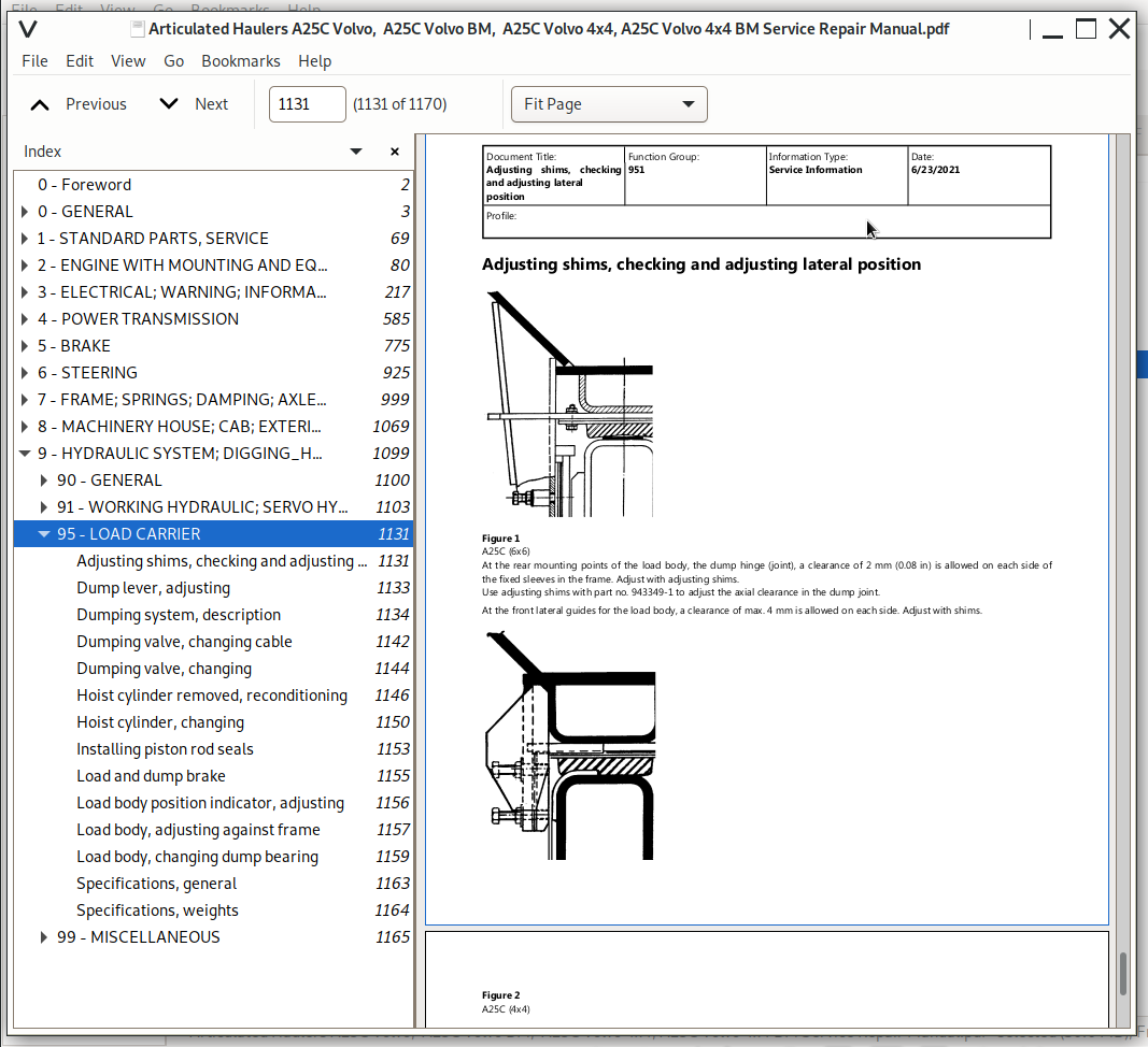
Adjusting shims, checking and adjusting lateral position.......1131
Dump lever, adjusting.......1133
Dumping system, description.......1134
Dumping valve, changing cable.......1142
Dumping valve, changing.......1144
Hoist cylinder removed, reconditioning.......1146
Hoist cylinder, changing.......1150
Installing piston rod seals.......1153
Load and dump brake.......1155
Load body position indicator, adjusting.......1156
Load body, adjusting against frame.......1157
Load body, changing dump bearing.......1159
Specifications, general.......1163
Specifications, weights.......1164
99 - MISCELLANEOUS.......1165
Hydraulic diagram A25C 4x4 with turn-around wheels - Image.......1165
Hydraulic diagram A25C 4x4 with turn-around wheels.......1166
Hydraulic diagram A25C 6x6 - Image.......1168
Hydraulic diagram A25C 6x6.......1169
Articulated Haulers A25C Volvo / A25C Volvo BM / A25C Volvo 4x4 / A25C Volvo 4x4 BM Service Repair Manual
![]()