
Daewoo Mega 250-V Wheeled Loader Repair Service Manual + Operation & Maintenance Manual
Complete service manual with electrical wiring diagrams for Daewoo Mega 250-V Wheeled Loader, with all the technical information to maintain, diagnose, repair, and rebuild like professional mechanics.
Daewoo Mega 250-V Wheeled Loaders workshop service & repair manual includes:
* Numbered table of contents easy to use so that you can find the information you need fast.
* Detailed sub-steps expand on repair procedure information
* Numbered instructions guide you through every repair procedure step by step.
* Troubleshooting and electrical service procedures are combined with detailed wiring diagrams for ease of use.
* Notes, cautions and warnings throughout each chapter pinpoint critical information.
* Bold figure number help you quickly match illustrations with instructions.
* Detailed illustrations, drawings and photos guide you through every procedure.
* Enlarged inset helps you identify and examine parts in detail.
MANUAL LIST:
M250-V Hydraulic Schematics.pdf
M250-V Electric Schematics.pdf
023-00050AE - Mega 250-V Shop Manual.pdf
022-00027AE - Mega 250-V Operation & Maintenance Manual.pdf
Total Pages: 733 pages
File Format: PDF (bookmarked, Searchable, Printable, high quality)
Language: English
022-00027AE - Mega 250-V Operation & Maintenance Manual....2
Safety....8
To the Operator of a Daewoo Wheel Loader....8
General Safety Essentials....9
Location of Safety Labels....10
Unauthorized Modifications....18
Work Site Precautions....18
Operation....20
Equipment....25
Maintenance....29
Shipping and Transportation....33
Operating Controls....34
Component Locations....35
Control Identification....39
Steering Console and Pedals....40
Transmission Display....47
Front Instrument Panel....49
Right Side Switch Panel....58
Various Cabin Locations....68
Heater and Air Conditioner Operation....72
Stereo....77
Seat Adjustment....81
Seat Belt....83
Door Side Latch....84
Fuse Box/Relay....85
Window Glass Breaking Tool....88
Operation....90
Instrument Panel Control Functions....90
New Machine Break-in Procedures....90
Engine Start and Stop....91
Machine Travel....100
Machine Shut Down....102
Additional Braking....104
Boom Raise Kickout....105
Bucket Angle Indicator....105
Boom Lower Kickout (Option)....106
Adjustment of Bucket Position Switch....106
Towing Machine....107
If Engine Stalls While Traveling....108
Allowable Water Depth....108
Inspection, Maintenance and Adjustment....110
Preventive Maintenance....110
Table of Recommended Lubricants....112
Fluid Capacities....114
Maintenance Intervals....115
10 Hour / Daily Service....117
50 Hour / Weekly Service....127
250 Hour / Monthly Service....134
500 Hour / 3 Month Service....143
1,000 Hour / 6 Month Service....146
1,500 Hour / 9 Month Service....152
2,000 Hour / Yearly Service....154
12,000 Hour / Six Year Service....157
Severe Conditions Maintenance....158
General Maintenance....159
Parking Brake Adjustment....161
Check Hydraulic Pressures....162
Tires and Wheels....166
Electrical System....168
Bolt Torque Chart....169
Long Term Storage....170
Transportation....172
Loading Machine on a Trailer....172
Summary of Safety Precautions for Lifting....173
Troubleshooting....174
Engine....174
Hydraulic System....177
Travel System....179
Steering....184
Braking....185
Electrical System....185
Specifications....186
General Specifications....186
Working Range and Dimensions....189
Working Capacities....191
Approximate Weight of Workload Materials....191
Index....194
023-00050AE - Mega 250-V Shop Manual....200
Safety....206
Wheel Loader Safety S0103010K....208
To the Operator of a Daewoo Wheel Loader....210
Learn Signal Words Used with Safety Alert Symbol....212
General Safety Essentials....213
Accessory Applications....213
Location of Safety Labels....213
Unauthorized Modifications....213
General Hazard Information....214
Safety Rules....214
Safety Features....214
Inside Operator's Compartment....215
Clothing and Personal Protective Items....215
Breathing Masks, Ear Protection May Be Required....216
Asbestos Dust Hazard Prevention....216
Mounting and Dismounting....216
Fuel, Oil and Hydraulic Fluid Fire Hazards....217
Precautions When Handling Fluids at High Temperature....217
Injury from Work Equipment....218
Fire Extinguisher and First Aid Kit....218
Protection from Falling or Flying Objects....219
Install Additional Safety Equipment If Conditions Require....219
Maintain Standard Safety Equipment in Good Condition....219
Attachment Precautions....220
Accumulator....220
Engine Ventilation....220
Window Glass Breaking Tool....221
Before Starting Engine....222
Work Site Precautions....222
Checks Before Starting Engine....223
Engine Starting....223
Before Operating Machine....224
Machine Operation....225
Operate While Seated at Operator’s Station ONLY....225
Seat Belts Should Be Used at All Times....225
Movement Alarms....225
Travel Precautions....226
Sloping Terrain Requires Caution....226
Avoid High-voltage Cables....227
Before Starting to Dig, Contact Authorities....227
Be Aware of Height Obstacles....227
Use Care on Loose Support....227
Use Solid Support Blocking....228
Digging Beneath Overhangs....228
Digging Beneath Wheel Loader....228
Stay Alert for People Moving Through Work Area....228
Be Aware of and Conform to Local Regulations....228
Never Use Ether Starting Aids....229
Observe General Safety Rules....229
Take Time to Provide Good Visibility....229
Keep "Pinch Point" Areas Clear - Use Caution in Reverse....230
Operate Carefully on Snow and Ice and in Very Cold Temperatures....230
Parking Machine....230
Shutdown Control Functions....231
Never Let Anyone Ride on Attachment....231
Maintenance....232
Use Warning Tag During Service....232
clean Before Inspection or Maintenance....232
Proper Tools....233
Use of Lighting....233
Fire Prevention and Explosion Prevention....233
Burn Prevention....234
Welding Repairs....235
Precautions for Removal, Installation, and Storage of Attachments....235
Precautions When Working on Machine....236
Lock Inspection Covers....236
Crushing Prevention and Cutting Prevention....236
Do Not Run Engine If Repairs or Work Are Being Performed Alone....236
Always Use Adequate Equipment Supports and Blocking....237
Do Not Work on Hot Engines or Hot Cooling or Hydraulic Systems....237
Hydraulic Cylinder Seals Require Periodic Replacement....237
High Pressure Hydraulic Lines Can Store a Great Deal of Energy....237
Precautions with High Pressure Line, Tubes and Hoses....238
Obtain Immediate Medical Attention if Pressurized Oil Pierces Skin.....238
Use Correct Replacement Fasteners Tightened to Proper Torque....239
Safety-critical Parts Must Be Replaced Periodically....239
Dispose of All Petroleum-based Oils and Fluids Properly....239
Check Tire Pressure and Condition....239
Battery....240
Battery Hazard Prevention....240
Disconnect Batteries Before Electrical Service or Electrical Welding....240
Use Low Heat Portable Lighting....241
Boost Starting or Charging Engine Batteries....241
Towing....242
Precautions When Towing....242
Shipping and Transportation....243
Obey State and Local Over-the-Road Regulations....243
Summary of Safety Precautions for Lifting....243
Specifications....244
Specifications for Mega 250-V S0203110C....246
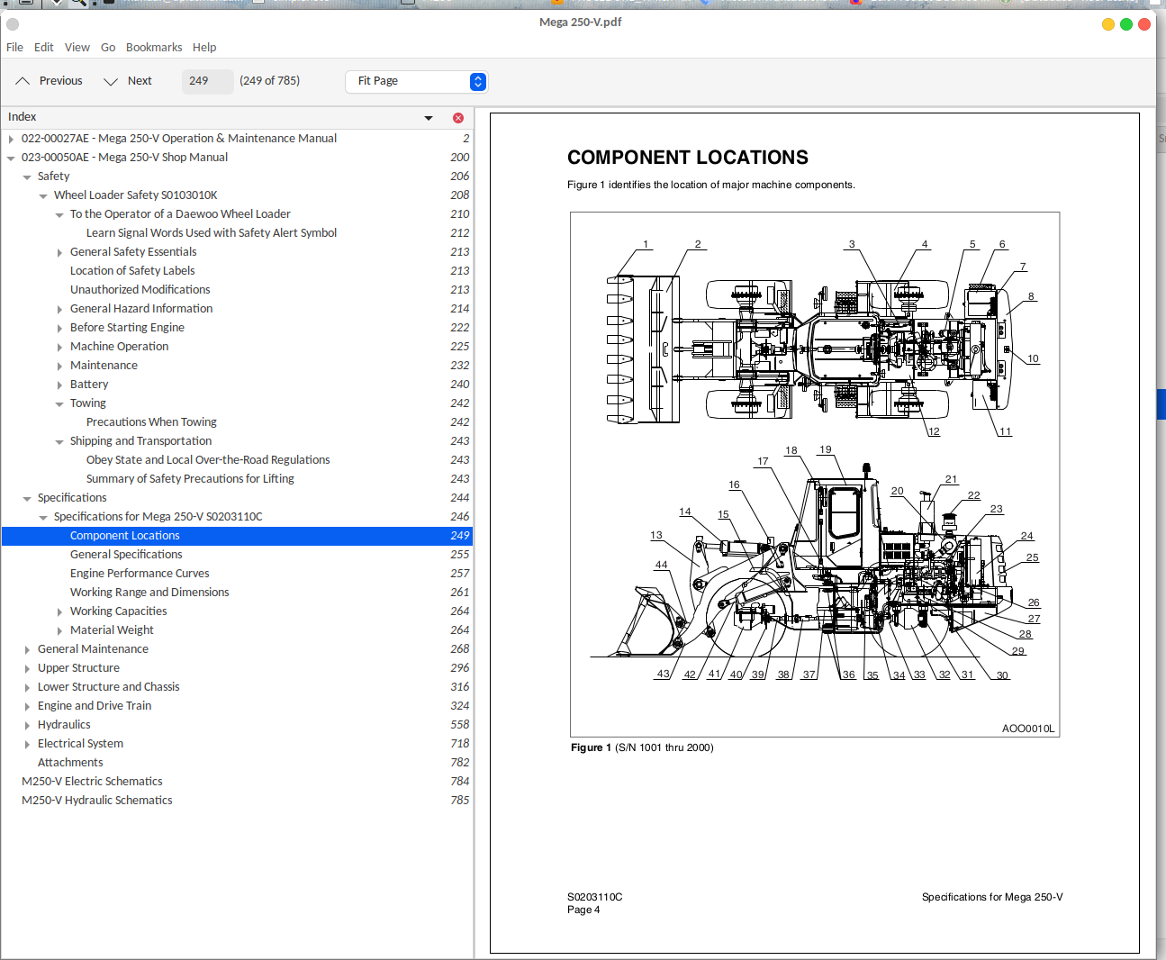
Component Locations....249
General Specifications....255
Engine Performance Curves....257
Working Range and Dimensions....261
Working Capacities....264
Bucket Capacity....264
Tipping Load....264
Material Weight....264
Approximate Weight of Workload Materials....264
General Maintenance....268
General Maintenance Procedures S0302000....270
Welding Precautions and Guidelines....272
Hydraulic System - General Precautions....273
Maintenance Service and Repair Procedure....274
General Precautions....274
Hydraulic System Cleanliness and Oil Leaks....275
Maintenance Precautions for Hydraulic System Service....275
Oil Leakage Precautions....275
Cleaning and Inspection....276
General Guidelines....276
Bearing inspection....277
Standard Torques S0309000....284
Torque Values for Standard Metric Fasteners....286
Torque Values for Standard U.S. Fasteners....287
Type 8 Phosphate Coated Hardware....289
Torque Values for Hose Clamps....290
Torque Values for Split Flanges....291
Torque Wrench Extension Tools....292
Torque Multiplication....292
Other Uses for Torque Wrench Extension Tools....293
Tightening Torque Specifications (Metric)....293
Upper Structure....296
Counterweight S0403030K....298
Specifications....300
Counterweight....300
Fuel Transfer Pump S0405500....302
General Description....304
Theory of Operation....304
Troubleshooting....305
Replacement of Rotor and Vane....305
Replacement of Rear Cover....306
Replacement of Armature....307
Hydraulic Oil Tank S0406060C....308
General Description....311
Parts List (M200-V)....311
Parts List (M250-V)....313
Specifications....315
Lower Structure and Chassis....316
Center Joint (Articulation Joint) S0502050C....318
General Description....320
Maintenance Standard....321
Engine and Drive Train....324
Axle (Volvo) S0602210C....326
Introduction....328
General Description....329
Outline....329
Disassembly and Assembly of Axle Units....332
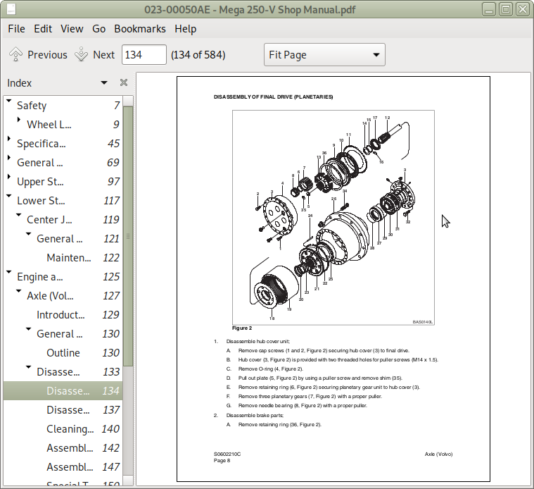
Disassembly of Final Drive (Planetaries)....333
Disassembly of Differential Unit....336
Cleaning and Inspection (Wear Limits and Tolerances)....339
Assembly of Differential Unit....341
Assembly of Final Drive (Planetaries)....346
Special Tool....349
Brake Bleeding Procedure....351
Parking Brake Caliper (Volvo) S0603000....352
General Description....354
Operation....354
Parking Brake Applied....355
Parking Brake Released....355
Parts List....356
Special Tools and Materials....356
Lubricants and Sealants....356
Troubleshooting, Testing and Adjustment....357
Parking Brake System....357
Checking and Adjusting Parking Brake....357
Measuring Pad Thickness....357
Measuring Disc / Pad Clearance....357
Measuring Procedure....358
Adjustment....358
Releasing the Parking Brake in Emergency Case....359
Disassembly....360
General....360
Changing Brake Pads....360
Work Sequence During Change of Brake Pads....360
Cleaning and Inspection (Wear Limits and Tolerances)....362
Reassembly....364
Air Conditioner S0605050K....370
General Description....372
Refrigerant Circulation....373
Control Panel....375
Control Specifications....376
Temperature Level Control and Display....377
Air Discharge According to Path Selection....378
Air-conditioning System Circuit Diagram....381
Troubleshooting....383
Weight of R134a Gas Used In Machines....387
Refrigerant System Repairs....389
Refrigerant Safe Handling Procedures....389
Repair and Replacement Procedure....390
Refrigerant Recovery....392
Vacuuming Refrigerant System....392
Leakage Check....393
Refrigerant Charging....394
Inspecting System For Leakage....396
Transmission and Torque Converter (ZF4WG190) S0607120C....398
Drive Train Description....402
Transmission and Torque Converter....403
Powershift Transmission....404
Transmission Control....404
The Chart of Measuring Points and Connection 4 WG-190....406
Oil Circuit Diagram 4WG-190....408
Transmission Electric Components....410
TCU (Transmission Control Unit)....411
Transmission Control Valve....411
Transmission Oil Temperature Sensor....412
Engine Pick-Up Sensor....412
Central Gear Pick-Up Sensor....412
Turbine Pick-Up Sensor....413
Output Speed Sensor....413
Shift Lever Switch (DW-3)....413
Auto Select Switch....415
Display....415
Transmission Electrical Circuits....416
T/M Controller Circuit....416
Traveling Circuits....417
Downshift....425
Transmission Cut Off....428
LIS (Load Isolation System) - Option....429
Installation View....430
Inner Section....430
Front View....431
Side View....432
Rear View....433
Special Tools....434
Gearshift System....434
Engine Connection....436
Pressure Oil Pump....437
Gearbox Housing....438
Input....440
Clutch....441
Output....447
Power Take-off....448
Hydraulic Control Unit (HSG94)....449
Disassembly....450
Reassembly....453
Transmission Disassembly....460
Hydraulic Control unit (HSG-94) and Duct plate....460
Engine Connection - Converter....461
Hydraulic Pump....463
Converter Back Pressure Valve....464
Remove output, Input and Clutches....465
Disassemble Clutch - KV and KR....470
Disassemble Clutch - K1, K2 and K3....473
Dissemble Clutch - K4....475
Disassemble Drive Shaft....476
Transmission Reassembly....478
Install Oil Tube....478
Reassemble Clutch - KV and KR....480
Reassemble Clutch - K1, K2 and K3....487
Reassemble Clutch - K4....494
Pre-assemble Drive Shaft....500
Pre-assemble and Install Output....501
Install Pre-assembled Drive Shaft and Clutches....503
Install Pump Shaft (Power Take-off)....506
Install Output Flanges....507
Converter Back Pressure Valve....509
Oil Feed Housing - Transmission Pump....509
Engine Connection - Converter....511
Converter Safety Valve....514
Mount Duct Plate and Hydraulic Control Unit....514
Install Plugs and Oil Level Tube....515
Speed Sensor and Inductive Transmitters....517
Setting Inductive Transmitter....518
Speed Sensor (Hall Sensor) N Output and Speedometer....519
Transmission Error Codes (ZF) S0607900C....522
Introduction....525
Abbreviations....525
Display....525
Description of Fault Codes....526
Display During Operation....527
Definition of Operating Modes....529
Normal....529
Substitute Clutch Control....529
Limp-home....529
Transmission shut Down....529
TCU Shut Down....529
Clutch Pack and Solenoid Valve Cross-reference Table....530
Table of Fault Codes....531
Table of Fault Codes - ERGO-Control....553
Measurement of Resistance at Actuator/ sensors and Cable....556
Actuator....556
Cable....556
Hydraulics....558
Accumulator S0703010K....560
General Description....562
Specifications....563
Cylinders S0705005K....566
General Description....569
Theory of Operation....570
Parts List....571
Troubleshooting, Testing and Adjustment....577
Disassembly....581
Cleaning and Inspection (Wear Limits and Tolerances)....583
Reassembly....584
Fan Drive Hydraulic Motor (Haldex) S0707110C....592
General Description....595
Theory of Operation....595
Parts List....599
Specifications....600
Troubleshooting, Testing and Adjustment....601
Tools Required....601
Disassembly....602
Inspect Parts for Wear....605
General Information....606
Reverse Shaft Rotation of Pump....606
Reassembly....607
Main Pump (Denison T67CCA Series) S0708500C....612
General Description....614
Theory of Operation....614
Parts List....615
Service Kits....617
Dimensions....618
Specification....619
Special Tools....620
Seal Driver....620
Protective Cone....620
Disassembly....621
Reassembly....625
Brake Pedal Valve S0709270C....630
General Description....632
Theory of Operation....632
Specification....633
Brake System....634
Brake and Pilot Supply Valve....634
Brake, Pilot and Fan Motor Supply Valve....635
Brake, Pilot and Fan Motor Supply Valve....636
Brake and Pilot Supply Valve....636
Brake, Pilot and Fan Motor Supply Valve....638
Main Control Valve (Toshiba) S0709456K....640
General Description....642
Specifications....644
Operation....645
Neutral....645
Bucket/option Spool Operation....645
Boom Spool Operation....646
Relief Valve....646
Operation (Main Relief Valve)....647
Operation (Port Relief Valve)....648
Pilot Control Valve S0709478C....650
General Description....652
Pilot Valve Operation....652
Standard....653
Option....655
Pilot System....657
Mega 200-V....658
Mega 250-V....659
Priority Valve S0709650....660
General Description....662
Theory of Operation....662
Parts List....664
Specifications....665
Special Tools....665
Disassembly....665
Cleaning and Inspection (Wear Limits and Tolerances)....667
Reassembly....668
Power Steering Unit S0709705C....672
General Description....674
Power Steering System....674
Gerotor Operation....677
Cushion Valve Operation....678
Parts List....679
Specifications....680
Special Tools....681
Troubleshooting, Testing and Adjustment....683
Disassembly....684
Cleaning and Inspection....688
Reassembly....689
Installation....700
Unloader Valve S0709860C....702
General Description....705
Theory of Operation....705
Unloader Cartridge Identification....707
Specifications....708
Hydraulic Schematic (Mega 250-V) S0793005C....710
General Description....712
Mega 250-V....713
Electrical System....718
Electrical System S0802015C....720
Overview....723
Electric Supply System....724
Engine Starting Circuit....726
Operation During Start Process....726
Operation After Start Process (Mega 200-V)....728
Operation After Start Process (Mega (250-V)....729
Engine Preheating System....730
Mega 200-V / 250-V (Tier I)....730
Mega 200-V / 250-V (Tier II)....733
Engine Stop System....736
Operation In Engine Running Mode....736
Operation In Engine Stop Mode....739
Charging System....741
Monitoring System....742
Instrument Panel....743
Function Check....744
Monitoring System Schematic....745
Operation....749
Windshield Wiper....755
Front windshield wiper....755
Rear Windshield wiper....756
Lighting System....759
Light Circuit (Mega 200-V)....759
Light Circuit (Mega 250-V)....763
Emergency Steering System (Option)....766
Block Diagram....766
Emergency Steering System Components....767
Emergency Steering System Electric Circuit....769
Electric Detent System....770
Electric Circuit....770
Boom Kick-Out....771
Return To Dig....772
Electrical Schematic (Mega 250-V) S0893005C....774
General Description....776
Mega 250-V (Tier I)....777
Mega 250-V (Tier II)....779
Attachments....782
M250-V Electric Schematics....784
M250-V Hydraulic Schematics....785
Daewoo Mega 250-V Wheeled Loader Repair Service Manual + Operation & Maintenance Manual
![]()