
Doosan DX420LC Crawler Excavator Repair Service Manual
Complete repair service manual with electrical wiring diagrams for Doosan DX420LC Crawler Excavator, with technical information to maintain, diagnose, repair, and service like professional mechanics.
Doosan DX420LC Crawler Excavator workshop service repair manual includes:
* Numbered table of contents easy to use so that you can find the information you need fast.
* Detailed sub-steps expand on repair procedure information
* Numbered instructions guide you through every repair procedure step by step.
* Troubleshooting and electrical service procedures are combined with detailed wiring diagrams for ease of use.
* Notes, cautions and warnings throughout each chapter pinpoint critical information.
* Bold figure number help you quickly match illustrations with instructions.
* Detailed illustrations, drawings and photos guide you through every procedure.
* Enlarged inset helps you identify and examine parts in detail.
Total Pages: 1,775 pages
File Format: PDF (bookmarked, Searchable, Printable, high quality)
Language: English
“K1009096E.pdf”
Doosan DX420LC Crawler Excavator Shop Manual
Serial Number 5001 and Up; K1009096E; 900 pages
MAIN SECTIONS
Safety
Track Excavator Safety... SP000256
Specifications
Specification for DX420LC.. SP000257
General Maintenance
General Maintenance Procedures... SP000016
Standard Torques... SP000017
Upper Structure
Cabin ... SP000018
Counterweight.. SP000265
Fuel Tank... SP000264
Swing Bearing.. SP000262
Swing Reduction Gear.. SP000249
Lower Structure and Chassis
Track Assembly ... SP000263
Air Conditioner ... SP000025
Engine and Drive Train
Drive Coupling (Main Pump)... SP000026
Hydraulics
Hydraulic System Troubleshooting, Testing and Adjustment ... SP000273
Accumulator... SP000028
Center Joint (Swivel)... SP000181
Cylinders.. SP000030
Swing Motor... SP000261
Travel Motor (With Gearbox) .. SP000266
Main Pump... SP000186
Control Valve (KVMG-400-DA)... SP000187
Remote Control Valve (Work Lever / Joystick) .. SP000189
Travel Control Valve (With Damper).. SP000070
Solenoid Valve Assembly ... SP000191
Breaker EPPR Valve (Opt) ... SP000192
Fan Motor (Vane Type)... SP000209
Gear Pump (Fan Cooling Drive) ... SP000208
Fan Cooling Flow In-Out Change Valve .. SP000207
Hydraulic Schematic (DX420LC).. SP000274
Electrical System
Electrical System .. SP000269
Electrical Schematic (DX420LC) .. SP000275
Attachments
Boom and Arm... SP000040
Bucket.. SP000041
“K1009096AE.pdf”
Doosan DX420LC Crawler Excavator Shop Manual
Serial Number 5327 and Up; K1009096AE; 862 pages
Table of Contents
Safety
Track Excavator Safety... SP000907
Specifications
Specification for DX420LC.. SP001755
General Maintenance
General Maintenance Procedures... SP000016
Standard Torques... SP000813
Upper Structure
Cabin ... SP001737
Counterweight.. SP001756
Fuel Tank... SP001757
Fuel Transfer Pump (Opt)... SP000021
Swing Bearing.. SP001856
Swing Reduction Gear.. SP001740
Lower Structure and Chassis
Track Assembly ... SP000263
Engine and Drive Train
Drive Coupling (Main Pump)... SP000026
Hydraulics
Hydraulic System Troubleshooting, Testing and Adjustment ... SP001758
Accumulator... SP000028
Center Joint (Swivel)... SP000181
Cylinders.. SP000030
Swing Motor... SP000261
Travel Motor (With Gearbox) .. SP000266
Main Pump... SP000186
Gear Pump (Fan Cooling Drive) ... SP000208
Main Control Valve ... SP000187
Remote Control Valve (Work Lever / Joystick) .. SP000189
Travel Control Valve (With Damper).. SP001743
Fan Motor (Vane Type)... SP000209
Fan Cooling Flow In-Out Change Valve .. SP000207
Solenoid Valve Assembly ... SP001622
Breaker EPPR Valve (Opt) ... SP000192
Hydraulic Schematic (DX420LC).. SP001769
Electrical System
Electrical System.. SP001759
Electrical Schematic DX420LC... SP001857
Attachments
Boom and Arm... SP001851
Bucket.. SP001852
...
TABLE OF CONTENTS
CENDX4200002 - Electrical Wiring Diagrams......1
DX420 Electrical Schematics......2
DX420 Hydraulic Schematics......3
DX420LC Performance Data......4
K1009096AE - DX420LC Shop Manual......5
DX420LC......5
Table of Contents......9
Safety......11
Track Excavator Safety......13
Safety Precautions......17
Applicable Models......17
To the Operator of a DOOSAN Excavator......18
Learn the Signal Words Used with the Safety Alert Symbol......20
General Safety Essentials......21
Accessory Applications......21
Lifting Capacity Rating Configuration......21
Location of Safety Labels......22
Summary of Safety Precautions for Lifting in Digging Mode......22
Unauthorized Modifications......23
General Hazard Information......23
Safety Rules......23
Safety Features......24
Inside Operator's Compartment......24
Clothing and Personal Protective Items......25
Breathing Masks, Ear Protection May Be Required......25
Vibration Level Information......25
Recommendations for Limiting Vibrations......26
Mounting and Dismounting......27
Fuel, Oil and Hydraulic Fluid Fire Hazards......27
Precautions When Handling Fluids at High Temperature......28
Asbestos Dust Hazard Prevention......28
Injury from Work Equipment......29
Fire Extinguisher and First Aid Kit......29
Protection from Falling or Flying Objects......30
Attachment Precautions......30
Accumulator......31
Indoor Ventilation......31
Emergency Exit......31
Before Starting Engine......32
Work Site Precautions......32
Checks Before Starting Engine......33
Engine Starting......34
Before Operating Machine......35
Machine Operation......36
When Swinging or Changing Direction of Travel......36
Travel Precautions......37
Traveling on Slopes......38
Prohibited Operations......38
Precautions for Operation......39
Avoid High Voltage Cables......40
Protecting Cabin from Falling Object (Optional)......40
Operate Carefully on Snow, Ice and in Very Cold Temperatures......41
Operations on Slopes......41
Parking Machine......42
Never Let Anyone Ride on Attachment......42
Maintenance......43
Warning Tag......43
Clean Before Inspection or Maintenance......43
Proper Tools......44
Use of Lighting......44
Fire Prevention and Explosion Prevention......44
Burn Prevention......45
Welding Repairs......45
Treatment for Electrical Welding to the Body Structure......46
Warning for Counterweight and Front Attachment Removal......47
Precautions for Removal, Installation, and Storage of Attachments......47
Precautions When Working on Machine......47
Lock Inspection Covers......48
Crushing Prevention and Cutting Prevention......48
Track Tension Adjustments Require Caution......48
Supports and Blocking for Work Equipment......49
Action When Abnormality Is Found During Inspection......49
Precautions with High-pressure Lines, Tubes and Hoses......49
Waste Materials......50
Battery......51
Battery Hazard Prevention......51
Boost Starting or Charging Engine Batteries......52
Towing......53
Precautions When Towing......53
Shipping and Transportation......54
Obey State and Local Over-the-Road Regulations......54
Lifting With Sling......54
Specifications......55
Specification for DX420LC......57
Safety Precautions......61
Applicable Models......61
General Description......63
Component Locations......64
General Dimensions (DX420LC)......66
Working Range......68
General Specifications......70
Engine Performance Curves (Per DIN6270 Standard)......72
Approximate Weight of Workload Materials......74
Performance Tests......76
Excavator Performance Standards......77
Test Conditions......77
Travel Speed and Travel Motor Balance (Steering Deviation) Tests......77
Speed Test......77
Travel Deviation......79
Swing Speed and Deceleration Force Test......79
Swing Speed Test......79
Swing Deceleration Force Test......80
Cylinder Performance Tests......81
Boom Cylinders Test......81
Arm Cylinder Test......81
Bucket Cylinder Test......81
Hydraulic Cylinder Natural Drop Test......81
Travel Motor Jack-up Test......82
General Maintenance......83
General Maintenance Procedures......85
Safety Precautions......89
Applicable Models......89
Welding Precautions and Guidelines......90
Hydraulic System - General Precautions......91
Maintenance Service and Repair Procedure......93
General Precautions......93
Hydraulic System Cleanliness and Oil Leaks......94
Maintenance Precautions for Hydraulic System Service......94
Oil Leakage Precautions......95
Cleaning and Inspection......96
General Guidelines......96
Bearing inspection......97
Normal Bearing......98
Bent Cage......98
Galling......99
Abrasive Step Wear......99
Etching......100
Misalignment......100
Indentations......100
Fatigue Spalling......101
Brinelling......101
Cage Wear......101
Abrasive Roller Wear......102
Cracked Inner Race......102
Smears......102
Frettage......103
Heat Discoloration......103
Stain Discoloration......103
Standard Torques......105
Safety Precautions......109
Applicable Models......109
Torque Values for Standard Metric Fasteners......110
Torque Values for Standard U.S. Fasteners......111
Type 8 Phosphate Coated Hardware......113
Torque Values for Hose Clamps......114
Torque Values for Split Flanges......115
Torque Wrench Extension Tools......116
Torque Multiplication......116
Other Uses for Torque Wrench Extension Tools......117
Tightening Torque Specifications (Metric)......118
I. "Loctite" Fastener Adhesives......119
II. "Loctite" Pipe Thread Sealant......119
III. "Loctite" gasket/flange sealer......119
IV. "Loctite" retaining compounds......120
V. "Loctite" Adhesives......120
Upper Structure......121
Cabin......123
Safety Precautions......127
Applicable Models......127
Removal......128
Installation......132
Counterweight......135
Safety Precautions......139
Applicable Models......139
General......140
Warning for Counterweight and Front Attachment Removal......140
Removal......142
Installation......143
Fuel Tank......145
Safety Precautions......149
Applicable Models......149
General Description......150
Parts List......150
Specifications......151
Removal......152
Installation......156
Start-up Procedures......158
Fuel Transfer Pump (Opt)......159
Safety Precautions......163
Applicable Models......163
General Description......164
Theory of Operation......164
Troubleshooting......165
Replacement of Rotor and Vane......165
Replacement of Rear Cover......166
Replacement of Armature......166
Swing Bearing......167
Safety Precautions......171
Applicable Models......171
Swing Bearing Maintenance......172
Operating Recommendation......172
Measuring Swing Bearing Axial Play......172
Measuring Bearing Lateral Play......172
Swing Bearing Basic Operation......173
Disassembly......173
Assembly......175
Swing Reduction Gear......177
Safety Precautions......181
Applicable Models......181
General Description......183
Theory of Operation......183
Parts List......184
Specifications......186
Troubleshooting, Testing and Adjustment......187
Removal......188
Disassembly......189
Assembly......193
Shaft and S/R Bearing Shrinkage Fitting......193
Assembly of the Carrier Subassembly......195
Washing of the Carrier......195
Washing of Planet Gears......195
Assembly of the Carrier Subassembly 1......196
Assembly of the Carrier Subassembly 2......199
Assembly of Main Case......203
Washing of the Casing and Other Components......203
Assembly of the Shaft and the Pinion......203
Assembly of the Seal and the Bearing......208
Assembly of the Ring Gear......212
Assembly of the Carrier......214
Test......219
Pneumatic Test......219
Noise and Abnormal Sound Test......220
Assembly of the Motor......221
Supply of Gear Oil......221
Assembly of the Motor......222
Installation......227
Lower Structure and Chassis......229
Track Assembly......231
Safety Precautions......235
Applicable Models......235
General Description......236
Track Tension......236
Cleaning and Inspection (Wear Limits and Tolerances)......239
Track Shoe......240
Lower Roller......242
Upper Roller......243
Front Idler......244
Track Shoes and Links......245
Track Removal......245
Track Installation......246
Front Idler Roller......248
Parts List......248
Front Idler Roller Disassembly......249
Front Idler Roller Reassembly......250
Lower Roller......252
Parts List......252
Lower Roller Removal......253
Lower Roller Disassembly......253
Lower Roller Reassembly......254
Lower Roller Installation......255
Upper Roller......256
Parts List......256
Upper Roller Removal......257
Upper Roller Disassembly......257
Upper Roller Reassembly......260
Track Spring and Track Adjusting Cylinder......262
Under Carrige Track Spring......263
Track Spring Assembly Diagram......263
Track Spring Disassembly Diagram......264
Disassembly of the Track Spring Assembly......265
Assembly of the Track Spring......267
Engine and Drive Train......271
Drive Coupling (Main Pump)......273
Safety Precautions......277
Applicable Models......277
Drive Coupling......278
Installation of Drive Coupling......279
Installation Procedure......279
Hydraulics......281
Hydraulic System Troubleshooting, Testing and Adjustment......283
Safety Precautions......287
Applicable Models......287
Hydraulic System - General Notes......288
Hydraulic Schematic......289
General Notes......289
Operation of Working Components......291
Boom Operating Circuit......291
Boom Up Circuit......291
Boom Down Circuit......292
Arm Operating Circuit......292
Arm Crowd Circuit......293
Arm Dump Circuit......293
Bucket Operating Circuit......294
Bucket Crowd Circuit......294
Bucket Dump Circuit......294
Swing Operating Circuit......294
Right Swing Operating Circuit......295
Left Swing Operating Circuit......295
Swing Relief Valve and Makeup Valve......295
Travel Operating Circuit......295
Forward Travel Circuit......296
Reverse Travel Circuit......296
Procedural Troubleshooting Baseline Recommendations......297
Initial Checks and Tests to Establish Operating Condition of the Excavator......297
Triage Summary......297
Pilot Pressure......299
Adjustment and Testing......299
Power Mode Valve......300
Current Signal and Hydraulic Pressure Adjustments......300
Pressure Up Valve......301
Checks and Adjustments......301
Pump Input Power Control......303
Pump Regulator Adjustment......303
Flow Meter and Flow Meter Kit Installation and Testing......306
Installation and Testing Procedure......306
Swing System Troubleshooting......308
Precautions/Initial Checks......308
Swing Relief Valve Checking and Adjustment......308
Troubleshooting – Swing Gearbox......310
Troubleshooting – Hydraulic Problems......312
Troubleshooting – Control Valve......314
Troubleshooting – Travel Control Valve......315
Troubleshooting – Joystick Control Valve......315
Accumulator......317
Safety Precautions......321
Applicable Models......321
General Description......322
Specifications......324
Center Joint (Swivel)......325
Safety Precautions......329
Applicable Models......329
General Description......330
Center Joint Disassembly Diagram......331
Disassembly......332
Reassembly......335
Cylinders......339
Safety Precautions......343
Applicable Models......343
General Description......344
Theory of Operation......344
Parts List......346
Special Tools and Materials......348
Piston Nut......348
Piston Jig......350
Steel Bushing Jig......352
Dust Wiper Jig......354
Slipper Seal Jig......356
Slipper Seal Straightening Jig......358
Disassembly......360
Reassembly......365
Swing Motor......369
Safety Precautions......373
Applicable Models......373
General Description......374
Theory of Operation......374
Structure......374
Circuit Diagram......374
Generation of Rotary Power......375
Operation of Relief Valve......376
Operation of Parking Brake......376
Makeup Check Valve......377
Operation of Time Delay Valve......377
External Pilot Pressure: When Pi = 0 (Large Tilt Angle)......377
Operation of Swing Reactionless Valve......377
Parts List......378
Specifications......380
Torques......380
Tools and Materials......381
Tools......381
Troubleshooting, Testing and Adjustment......382
General Precautions......382
How to Check Faults of Hydraulic Motor......382
Troubleshooting......382
Disassembly......384
General Cautions......384
Disassembly of drive shaft subassembly......384
Disassembly of the cylinder block subassembly......387
Disassembly of the rear cover subassembly......388
Cleaning and Inspection (Wear Limits and Tolerances)......390
Reassembly......391
General Cautions......391
Reassembly of drive shaft subassembly......391
Assembly of Cylinder Block Assembly Subassembly......394
Assembly of Rear Cover Assembly Subassembly......398
Air Pressure Test......402
Oil Leakage Check......402
Installation of test bench......403
Travel Motor (With Gearbox) ......405
Safety Precautions......409
Applicable Models......409
Travel Motor (M3V270/160A)......410
Specifications......410
Outline Dimensions......410
Specifications......411
Structure and Function......412
Structure......412
Explanation of Structure......414
Function......416
Disassembly and Assembly......419
Tools and Jigs......419
Disassembly......420
General Instructions......420
Disassembling Procedure......420
Reassembly......424
General Instructions......424
Reassembly......424
Maintenance Standard......427
Maintenance of Parts......427
Maintenance Standard......427
Fastening Torque......428
Troubleshooting......429
General instructions......429
Cause of Trouble and Remedy......429
Reduction Gear (M3V270 / 160A-RG7.5)......431
Specifications......431
Outline Dimensions......431
Specifications......431
Structure and Operation......432
Structure......432
Operation......433
Disassembly and Assembly......434
Tools......434
Disassembling Reduction Unit......435
Preparation for disassembling......435
Setting Reduction Unit on Work stand for Disassembling......435
Removing Cover......436
Removing Carrier 1 Assembly......436
Removing Carrier 2 Assembly......437
Removing Housing Assembly......437
Disassembling Housing Assembly......438
Removing Floating Seal......438
Disassembling Carrier 1 Assembly......439
Disassembling Carrier 2 Assembly......440
Assembling......440
General Notes......440
Assembling Carrier 2 Assembly......440
Assembling Carrier 1 Assembly......441
Installing Floating Seal......442
Assembling Housing......443
Determining Shim Thickness For Angular Bearings......444
Pressing Motor Into Assembly......444
Installation Carrier 2 Assembly......445
Carrier 1 Assembly......446
Installing Cover......446
Filling Gear Oil......446
Maintenance......447
Inspection Before Re-assembling......447
Maintenance Standards......447
Fastening Torque......448
Inspection After Assembling......449
Lubrication......449
Rotating Inspection......449
Brake Valve (RBV - 24DL4)......450
Specification......450
Outline Dimensions......450
Specifications......451
Structure and Operation......451
Structure......451
Function......452
Operation......453
Disassembling and Reassembling......457
Preparation for Disassembling......457
Tools......457
Disassembling Procedure......457
Reassembling......458
Inspection Before Reassembling......458
Instructions on Reassembling......458
Fastening Torque......458
Reassembling Procedure......459
Troubleshooting......460
Main Pump......461
Safety Precautions......465
Applicable Models......465
ectional View......466
A8VO200LA1KH1/63......466
General Repair Guidelines......468
Seal Kits and Sub- assemblies......470
Sealing the Drive Shaft......474
Gear Pump Sealing......476
Remove the Control Housing......478
Control Module......482
Control Module LR......482
Control Module H......483
Removing the Controller......484
Valve Plate With Valves......486
Remove the Rotary Groups......487
Remove the Intermediate Wheel......490
Remove Auxiliary Drive......492
Inspection......495
Re-fitting the Rotary Group......500
Pump Assembly......502
Assembly Guideline......503
Adjustment of the Hydraulic Component of the Rotary Group......504
Hydraulic Component - Measurement "D"......505
Measuring Device - Hydraulic Component 452 269......505
Mounting Position......506
Measuring Procedure......508
Installation of Control Housing......509
Assembly of Intermediate Wheel......512
Installation of Gear Pump......513
Installation of Cover / Auxiliary Drive......514
Assembly Guidelines for Tightening Torques......515
Bolts (To N 08.001)......515
Plugs with Internal Hexagon and Profile Seal Ring (to N 02.009)......516
Seal-lock - Sealing Nuts (to N 02.100)......517
Gear Pump (Fan Cooling Drive)......519
Safety Precautions......523
Applicable Models......523
Disassembling Single Gear Pump......524
Reassembling Single Gear Pump......527
Disassembling Double Gear Pump(Opt)......530
Reassembling Double Gear Pump(Opt)......533
Main Control Valve......537
Safety Precautions......541
Applicable Models......541
General Description......542
When All Spools are in Neutral......542
Neutral Passage (Figure 1 and Figure 2)......542
Signal Passage (Figure 2)......544
Single Operation......546
Travel Spool Shifting (Figure 3 and Figure 4)......546
Swing Spool Shifting (Figure 4)......548
Boom Spool Shifting......549
Spare Spool Shifting (Figure 8)......552
Bucket Spool Shifting (Figure 8)......552
Arm Spool Shifting......553
Neutral-cut Spool Shifting (Figure 11)......556
Parallel Throttle for Arm (Figure 11)......556
Relief Valve......557
Combined Operation......558
Travel Combined Operation (Figure 13)......558
Swing Combined Operation (Figure 14)......560
Anti Drift Valve......561
Main Relief Valve......561
Overload Relief Valve......562
Low Pressure Relief Valve......564
Parts List......565
Spool Assembly (4, Bucket)......569
Spool Assembly (5, Boom)......569
Spool Assembly (6, Travel)......569
Spool Assembly (7, Straight Travel)......570
Spool Assembly (8, Arm1)......570
Spool Assembly (9, Service)......570
Spool Assembly (10, Boom 2)......571
Spool Assembly (11, Swing)......571
Spool Assembly (3, Arm 2)......571
Spool Assembly (20, Arm Regeneration Release Valve......571
Spool Assembly (24)......572
Poppet Assembly (36)......572
Plug Assembly (51)......572
Plug Assembly (58)......572
Relief Valve Assembly (48)......573
Relief Valve Assembly (49)......573
Relief Valve Assembly (50)......574
Specifications......574
Troubleshooting, Testing and Adjustment......575
General......575
Relief Valve......576
Hydraulic System......576
Adjustment of Relief Valve......576
Main Relief Valve......576
Over Load Relief Valve......577
Disassembly......578
General Instructions for Disassembly......578
Disassembly of Main Spool (3) - (11)......578
Disassembly of Subspool (24)......579
Disassembly of Subspool (20)......579
Disassembly of Anti Drift Valve of Boom and Arm......580
Disassembly of Swing Load Check......580
Disassembly of Load Check......581
Disassembly of Other Check Valves......581
Disassembly Of Flange......581
Disassembly of Relief Valve......582
Disassembly of Other Flange......582
Disassembly of Main Relief Valve......583
Disassembly of Overload Relief Valve......584
Disassembly of Low Pressure Relief Valve......584
Cleaning and Inspection (Wear Limits and Tolerances)......585
Cleaning......585
Inspection......585
Reassembly......586
Subassembly......586
Main Spool (3) - (11)......586
Subspool (20)......586
Subspool (24)......587
Boom, Arm Anti Drift Valve......587
Swing Load Check......587
Reassembly of Control Valve......587
Reassembly of Load Check Valve......587
Reassembly of Swing Load Check......588
Reassembly of Other Check Valve......588
Reassembly of Flange......589
Reassembly of Boom and Arm Anti Drift Valve......589
Reassembly of Relief Valve......589
Reassembly of Subspool (24)......589
Reassembly of Subspool (20)......590
Reassembly of Main Spool (3) - (11)......590
Reassembly of Other Plugs......590
Reassembly of Main Relief Valve......591
Reassembly of Overload Relief Valve......592
Reassembly of Low Pressure Relief Valve......592
Installation......593
Start-up Procedures......593
Remote Control Valve (Work Lever / Joystick)......595
Safety Precautions......599
Applicable Models......599
General Description......601
Structure......601
Function......601
Parts List......602
Specifications......604
Performance......604
Torques......604
Tools and Materials......604
Disassembly......605
Cleaning and Inspection (Wear Limits and Tolerances)......609
Reassembly......609
Start-up Procedures......615
Travel Control Valve (With Damper)......617
Safety Precautions......621
Applicable Models......621
General Description......622
Theory of Operation......622
Deceleration Valve......623
Dampening Parts of the Control Section......624
Causes of Faults and Measures......627
Parts List......628
Specifications......629
Torques......629
Removal......630
Disassembly......631
Cleaning and Inspection (Wear Limits and Tolerances)......634
Assembly......635
Installation......641
Startup Procedures......642
Fan Motor (Vane Type)......643
Safety Precautions......647
Applicable Models......647
Parts list......648
Introduction and Description......649
General......649
Description......649
Applications......649
Operation......650
Operating Characteristics - Typical......651
Performance Data......651
Loads on Shaft......652
Loads on Shaft......652
Lifetime Under Load......652
Mounting Flange and Coupling......653
Mounting Flange......653
Misalignment......653
Loads on Shaft......653
Splined Shafts......653
Shafts......654
Taper Shafts......654
Pipe Connection......654
Pipe......654
Flange Connections......655
External Drain......655
Cleanliness and Seals......656
Fluid Cleanliness......656
Seals S1 : Nbr (Nitrile Base Polymere)......656
Seals S4 : Epr (Ethylene Propylene Polymere)......656
Seals S5 : Fpm (Fluorocarbon)......656
Maintenance......657
General......657
Disassembly......657
Reassembly......659
Priming......661
Cold Starting......661
Changing Porting Position......661
Cartridge Replacement......662
End Cap Replacement......662
Shaft Replacement......662
Shaft Seal Replacement......662
Seal Driver......663
Couping Dimensions......663
Taper Keyed Shafts......663
Fan Cooling Flow In-Out Change Valve......665
Safety Precautions......669
Applicable Models......669
Cooling Fan a Change of Direction Valve......670
Solenoid Valve Assembly......671
Safety Precautions......675
Applicable Models......675
5Solenoid Valve......676
Parts List......676
Functions of 5Solenoid Valve Assembly......677
Functions and Operations of Solenoid Valves......677
Detailed Functions and Operations of Solenoid Valves......677
Assembly Diagram and Tools Required......680
Cautions During Disassembly and Reassembly......681
Solenoid Valve Diagram......682
Check Points and Solutions for Problems......683
Checking of Pilot Pressure for Defects......683
2Solenoid Valve......684
Parts List......684
Assembly Diagram and Tools Required......685
Cautions During Disassembly and Reassembly......686
Solenoid Valve Diagram......687
Troubleshooting Guide......687
Breaker EPPR Valve (Opt)......689
Safety Precautions......693
Applicable Models......693
Structure......694
Numbers and Names of Parts......694
Functions and Operation......695
Cautions for Operation......695
Maintenance Instructions......696
Maintenance......696
Bolt Tightening Torque......696
Tools Used for Disassembly and Assembly......696
Disassembly......697
Assembly......698
Hydraulic Schematic (DX420LC)......701
Safety Precautions......705
Applicable Models......705
DX420LC......707
Electrical System......708
Electrical System......710
Safety Precautions......715
Applicable Models......715
Introduction......716
Electrical Supply System......717
Engine Starting Circuit......719
Start Operation......719
After Start......721
Engine Preheating System......723
Engine Stop......725
Charging System......727
Monitoring System......728
Instrument Panel......729
Monitoring System Schematic......731
Operation......733
Instruments......733
Warning and Indicator Lights......735
Indication of Warning Lights......735
Indication of Multifunction Gauge......736
Initial Operation......738
Mode Selector Switch......738
Graphic Information Area Display......739
Overview......739
Main Menus for the Graphic Display Area......740
Menu Selector Buttons......740
Main Menu......741
Language......741
Set Clock......742
Filter/Oil Info......742
Adjust Display......743
Set Password......744
Special Menu......745
Entering/Accessing and Exiting/Escaping Menus......745
Special Menu Selections......746
Electronic Hydraulic Control System (eEPOS)......763
Control System Schematic......763
Power Mode Control......765
Operation......767
Power / Economy Mode Control Circuit Diagram......771
Engine Control System......773
Engine Control Dial......774
Engine Control Circuit Diagram......775
Automatic Deceleration Control (Auto Idle Control)......777
Engine Overheat Protection System......779
Power Boost Mode......781
Operation......781
Power Boost Control Circuit Diagram......783
Automatic Travel Speed Control......785
Automatic Travel Speed Control Circuit Diagram......787
Selfdiagnostic Function......788
eEPOS Controller......788
Air Conditioner System......790
Outline......790
Internal and External Filters......791
AirConditioning System Layout......793
Air Conditioner/heater Circuit Diagram......794
Air Conditioner/heater Unit......795
Ambient Air Temperature Sensor......800
Sun Sensor......801
Control Panel......801
Compressor......809
Receiver Dryer......809
Troubleshooting......810
Weight of R134a Gas Used In Machines......812
Refrigerant System Repairs......813
Refrigerant Safe Handling Procedures......813
Repair and Replacement Procedure......815
Refrigerant Recovery......817
Vacuuming Refrigerant System......817
Leakage Check......819
Refrigerant Charging......819
Inspecting System For Leakage......821
Wiper System......822
Wiper Circuit......822
Wiper operation......823
Lighting System......824
Lighting System Circuit Diagram......824
Kind of Light......825
Operation......825
Overload Warning Device......826
Overload Warning Device Circuit Diagram......826
Audio Controller......827
Audio Controller Circuit Diagram......827
Electrical Schematic DX420LC......830
Safety Precautions......834
Applicable Models......834
DX420LC......836
Attachments......837
Boom and Arm......839
Safety Precautions......843
Applicable Models......843
Front Attachment Pin Specifications......844
DX300LC......845
DX340LC / DX350LC......846
DX420LC......847
DX480LC / DX520LC......848
Front Attachment - Removal and Installation......849
Arm Removal Procedure......849
Boom Removal Procedure......851
Installation......852
Arm Installation Procedure......852
Boom Installation Procedure......852
Start-up Procedures......853
Bucket......855
Safety Precautions......859
Applicable Models......859
Bucket Tooth Inspection and Replacement......860
Bucket O-ring Replacement......861
Bucket Shimming Procedures......863
New Bucket Installation......863
Shimming Procedures for Installed Bucket......864
Bucket Attachment, Removal and Reversal......865
Detaching the Bucket......865
Attaching the Bucket......865
Reversing the Bucket......866
K1009096E - DX420LC Shop Manual......867
Table of Contents......869
Safety Precautions......877
Safety......871
Applicable Models......877
To the Operator of a DOOSAN Daewoo Excavator......878
Learn the Signal Words Used with the Safety Alert Symbol......880
General Safety Essentials......882
Accessory Applications......882
Lifting Capacity Rating Configuration......882
Location of Safety Labels......883
Summary of Safety Precautions for Lifting in Digging Mode......884
Unauthorized Modifications......885
General Hazard Information......885
Safety Rules......885
Safety Features......885
Inside Operator's Compartment......886
Clothing and Personal Protective Items......886
Breathing Masks, Ear Protection May Be Required......887
Vibration Level Information......887
Recommendations for Limiting Vibrations......887
Mounting and Dismounting......888
Fuel, Oil and Hydraulic Fluid Fire Hazards......889
Precautions When Handling Fluids at High Temperature......889
Asbestos Dust Hazard Prevention......890
Injury from Work Equipment......890
Fire Extinguisher and First Aid Kit......890
Protection from Falling or Flying Objects......891
Attachment Precautions......892
Accumulator......892
Indoor Ventilation......892
Emergency Exit......893
Before Starting Engine......894
Work Site Precautions......894
Checks Before Starting Engine......895
Engine Starting......895
Before Operating Machine......896
Machine Operation......898
When Swinging or Changing Direction of Travel......898
Travel Precautions......899
Traveling on Slopes......900
Prohibited Operations......900
Precautions for Operation......901
Avoid High Voltage Cables......902
Protecting Cabin from Falling Object (Optional)......902
Operate Carefully on Snow, Ice and in Very Cold Temperatures......903
Operations on Slopes......903
Parking Machine......904
Never Let Anyone Ride on Attachment......904
Maintenance......905
Warning Tag......905
Clean Before Inspection or Maintenance......905
Proper Tools......906
Use of Lighting......906
Fire Prevention and Explosion Prevention......906
Burn Prevention......907
Welding Repairs......907
Treatment for Electrical Welding to the Body Structure......908
Warning for Counterweight and Front Attachment Removal......909
Precautions for Removal, Installation, and Storage of Attachments......909
Precautions When Working on Machine......910
Lock Inspection Covers......910
Crushing Prevention and Cutting Prevention......910
Track Tension Adjustments Require Caution......911
Supports and Blocking for Work Equipment......911
Action When Abnormality Is Found During Inspection......911
Precautions with High-pressure Lines, Tubes and Hoses......912
Waste Materials......913
Battery......914
Battery Hazard Prevention......914
Boost Starting or Charging Engine Batteries......915
Towing......916
Precautions When Towing......916
Shipping and Transportation......917
Obey State and Local Over-the-Road Regulations......917
Lifting With Sling......917
Specifications......919
Specification for DX420LC......921
Safety Precautions......925
Applicable Models......925
General Description......927
Component Locations......928
General Dimensions (DX420LC)......930
Working Range......932
General Specifications......934
Engine Performance Curves (Per DIN 6270 Standard)......936
Approximate Weight of Workload Materials......938
Performance Tests......940
Excavator Performance Standards......941
Test Conditions......941
Travel Speed and Travel Motor Balance (Steering Deviation) Tests......941
Speed Test......941
Travel Deviation......943
Swing Speed and Deceleration Force Test......943
Swing Speed Test......943
Swing Deceleration Force Test......944
Cylinder Performance Tests......945
Boom Cylinders Test......945
Arm Cylinder Test......945
Bucket Cylinder Test......945
Hydraulic Cylinder Natural Drop Test......945
Travel Motor Jack-up Test......946
General Maintenance Procedures......949
Safety Precautions......953
Applicable Models......953
Welding Precautions and Guidelines......954
Hydraulic System - General Precautions......955
Maintenance Service and Repair Procedure......957
General Precautions......957
Hydraulic System Cleanliness and Oil Leaks......958
Maintenance Precautions for Hydraulic System Service......958
Oil Leakage Precautions......959
Cleaning and Inspection......960
General Guidelines......960
Bearing inspection......961
Normal Bearing......962
Bent Cage......962
Galling......963
Abrasive Step Wear......963
Etching......964
Misalignment......964
Indentations......964
Fatigue Spalling......965
Brinelling......965
Cage Wear......965
Abrasive Roller Wear......966
Cracked Inner Race......966
Smears......966
Frettage......967
Heat Discoloration......967
Stain Discoloration......967
Standard Torques......969
Safety Precautions......973
Applicable Models......973
Torque Values for Standard Metric Fasteners......974
Torque Values for Standard U.S. Fasteners......975
Type 8 Phosphate Coated Hardware......977
Torque Values for Hose Clamps......978
Torque Values for Split Flanges......979
Torque Wrench Extension Tools......980
Torque Multiplication......980
Other Uses for Torque Wrench Extension Tools......981
Tightening Torque Specifications (Metric)......981
I. "Loctite" Fastener Adhesives......983
II. "Loctite" Pipe Thread Sealant......983
III. "Loctite" gasket/flange sealer......983
IV. "Loctite" retaining compounds......984
V. "Loctite" Adhesives......984
Upper Structure......985
Cabin......987
Safety Precautions......991
Applicable Models......991
Removal......992
Installation......994
Counterweight......997
Safety Precautions......1001
Applicable Models......1001
General......1002
Warning for Counterweight and Front Attachment Removal......1002
Removal......1004
Installation......1006
Fuel Tank......1007
Safety Precautions......1011
Applicable Models......1011
General Description......1012
Parts List......1014
Specifications......1015
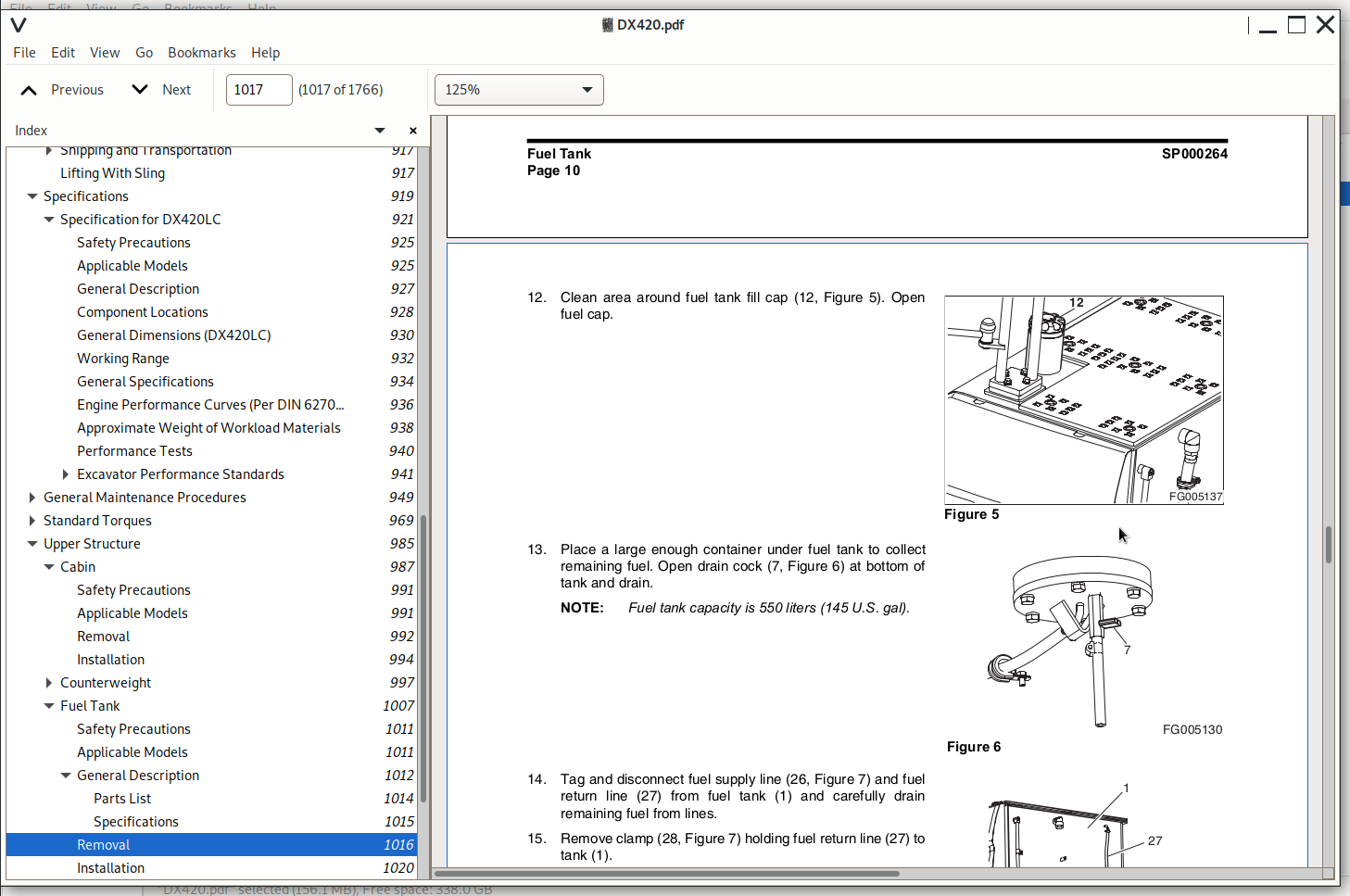
Removal......1016
Installation......1020
Start-up Procedures......1022
Swing Bearing......1023
Safety Precautions......1027
Applicable Models......1027
Swing Bearing Maintenance......1028
Operating Recommendation......1028
Measuring Swing Bearing Axial Play......1028
Measuring Bearing Lateral Play......1028
Swing Bearing Basic Operation......1029
Disassembly......1029
Assembly......1031
Swing Reduction Gear......1033
Safety Precautions......1037
Applicable Models......1037
General Description......1039
Theory of Operation......1039
Parts List......1040
Specifications......1042
Troubleshooting, Testing and Adjustment......1043
Removal......1044
Disassembly......1045
Assembly......1049
Shaft and S/R Bearing Shrinkage Fitting......1049
Assembly of the Carrier Subassembly......1051
Washing of the Carrier......1051
Washing of Planet Gears......1051
Assembly of the Carrier Subassembly 1......1052
Assembly of the Carrier Subassembly 2......1055
Assembly of Main Case......1059
Washing of the Casing and Other Components......1059
Assembly of the Shaft and the Pinion......1059
Assembly of the Seal and the Bearing......1064
Assembly of the Ring Gear......1068
Assembly of the Carrier......1070
Test......1075
Pneumatic Test......1075
Noise and Abnormal Sound Test......1076
Assembly of the Motor......1077
Supply of Gear Oil......1077
Assembly of the Motor......1078
Installation......1083
Lower Structure and Chassis......1085
Track Assembly......1087
Safety Precautions......1091
Applicable Models......1091
General Description......1092
Track Tension......1092
Cleaning and Inspection (Wear Limits and Tolerances)......1095
Track Shoe......1096
Lower Roller......1098
Upper Roller......1099
Front Idler......1100
Track Shoes and Links......1101
Track Removal......1101
Track Installation......1102
Front Idler Roller......1104
Parts List......1104
Front Idler Roller Disassembly......1105
Front Idler Roller Reassembly......1106
Lower Roller......1108
Parts List......1108
Lower Roller Removal......1109
Lower Roller Disassembly......1109
Lower Roller Reassembly......1110
Lower Roller Installation......1111
Upper Roller......1112
Parts List......1112
Upper Roller Removal......1113
Upper Roller Disassembly......1113
Upper Roller Reassembly......1116
Track Spring and Track Adjusting Cylinder......1118
Under Carrige Track Spring......1119
Track Spring Assembly Diagram......1119
Track Spring Disassembly Diagram......1120
Disassembly of the Track Spring Assembly......1121
Assembly of the Track Spring......1123
Air Conditioner SP000025......1127
Safety Precautions......1131
Applicable Models......1131
Air Conditioner System......1132
Outline......1132
Internal and External Filters......1133
How to check Indoor air filter......1133
How to check outdoor air filter......1133
Air-Conditioning System Layout......1135
Air Conditioner/Heater Circuit Diagram......1136
Air Conditioner/Heater Unit......1137
Air Flow Diagram......1137
Door Open by Vent Modes......1138
Main Components......1138
Actuator - Internal/external air exchange......1140
Air Flow Control Module......1140
Relay - Blower......1141
Relay - A/C......1141
Duct Sensor......1141
Water Temp Sensor......1142
Internal Air Temp Sensor......1142
Ambient Air Temperature Sensor......1142
Sun Sensor......1143
Control Panel......1143
Appearance and Terminal Arrangement......1143
Terminal Terms......1144
Control Logic......1144
Self Diagnosis......1149
Ambient Temp Display......1150
Compressor......1151
Receiver Dryer......1151
Troubleshooting......1152
Refrigerant Pressure Check......1152
Weight of R134a Gas Used In Machines......1155
Refrigerant System Repairs......1156
Refrigerant Safe Handling Procedures......1156
Repair and Replacement Procedure......1157
Refrigerant Recovery......1159
Vacuuming Refrigerant System......1159
Leakage Check......1160
Refrigerant Charging......1161
Inspecting System For Leakage......1163
Engine and Drive Train......1165
Drive Coupling (Main Pump)......1167
Safety Precautions......1171
Applicable Models......1171
Drive Coupling......1172
Installation of Drive Coupling......1173
Installation Procedure......1173
Hydraulics......1175
Hydraulic System Troubleshooting, Testing and Adjustment......1177
Safety Precautions......1181
Applicable Models......1181
Hydraulic System - General Notes......1182
Hydraulic Schematic......1184
General Notes......1184
Operation of Working Components......1186
Boom Operating Circuit......1186
Boom Up Circuit......1186
Boom Down Circuit......1187
Arm Operating Circuit......1187
Arm Crowd Circuit......1188
Arm Dump Circuit......1188
Bucket Operating Circuit......1189
Bucket Crowd Circuit......1189
Bucket Dump Circuit......1189
Swing Operating Circuit......1189
Right Swing Operating Circuit......1190
Left Swing Operating Circuit......1190
Swing Relief Valve and Makeup Valve......1190
Travel Operating Circuit......1190
Forward Travel Circuit......1191
Reverse Travel Circuit......1191
Procedural Troubleshooting Baseline Recommendations......1192
Initial Checks and Tests to Establish Operating Condition of the Excavator......1192
Triage Summary......1192
Pilot Pressure......1194
Adjustment and Testing......1194
Power Mode Valve......1195
Current Signal and Hydraulic Pressure Adjustments......1195
Boom/Front Priority Valve......1197
Control Valve Pressure and Current Adjustments......1197
Pressure Up Valve......1198
Checks and Adjustments......1198
Pump Input Power Control......1200
Pump Regulator Adjustment......1200
Flow Meter and Flow Meter Kit Installation and Testing......1203
Installation and Testing Procedure......1203
Swing System Troubleshooting......1205
Precautions/Initial Checks......1205
Swing Relief Valve Checking and Adjustment......1205
Troubleshooting - Swing Gearbox......1208
Troubleshooting - Hydraulic Problems......1209
Troubleshooting - Control Valve......1210
Troubleshooting - Travel Control Valve......1212
Troubleshooting - Joystick Control Valve......1212
Accumulator......1215
Safety Precautions......1219
Applicable Models......1219
General Description......1220
Specifications......1222
Center Joint (Swivel)......1223
Safety Precautions......1227
Applicable Models......1227
General Description......1228
Center Joint Disassembly Diagram......1229
Disassembly......1230
Reassembly......1233
Cylinders......1237
Safety Precautions......1241
Applicable Models......1241
General Description......1242
Theory of Operation......1242
Parts List......1244
Special Tools and Materials......1246
Piston Nut......1246
Piston Jig......1248
Steel Bushing Jig......1250
Dust Wiper Jig......1252
Slipper Seal Jig......1254
Slipper Seal Straightening Jig......1256
Disassembly......1258
Reassembly......1263
Swing Motor......1267
Safety Precautions......1271
Applicable Models......1271
General Description......1272
Parts List......1272
Specifications......1274
Torques......1274
Theory of Operation......1275
Structure......1275
Circuit Diagram......1275
Generation of Rotary Power......1276
Operation of Relief Valve......1277
Operation of Parking Brake......1277
Makeup Check Valve......1278
Operation of Time Delay Valve......1278
External Pilot Pressure: When Pi = 0 (Large Tilt Angle)......1278
Operation of Swing Reactionless Valve......1278
Tools and Materials......1279
Tools......1279
Troubleshooting, Testing and Adjustment......1280
General Precautions......1280
How to Check Faults of Hydraulic Motor......1280
Troubleshooting......1280
Disassembly......1282
General Cautions......1282
Disassembly of drive shaft subassembly......1282
Disassembly of the cylinder block subassembly......1285
Disassembly of the rear cover subassembly......1286
Cleaning and Inspection (Wear Limits and Tolerances)......1289
Reassembly......1289
General Cautions......1289
Reassembly of drive shaft subassembly......1289
Assembly of Cylinder Block Assembly Subassembly......1292
Assembly of Rear Cover Assembly Subassembly......1296
Air Pressure Test......1300
Oil Leakage Check......1300
Installation of test bench......1301
Travel Motor (With Gearbox) SP000266......1303
Safety Precautions......1307
Applicable Models......1307
Travel Motor (M3V270/160A)......1308
Specifications......1308
Outline Dimensions......1308
Specifications......1309
Structure and Function......1310
Structure......1310
Explanation of Structure......1312
Function......1314
Disassembly and Assembly......1317
Tools and Jigs......1317
Disassembly......1318
General Instructions......1318
Disassembling Procedure......1318
Reassembly......1322
General Instructions......1322
Reassembly......1322
Maintenance Standard......1325
Maintenance of Parts......1325
Maintenance Standard......1325
Fastening Torque......1326
Troubleshooting......1327
General instructions......1327
Cause of Trouble and Remedy......1327
Reduction Gear (M3V270 / 160A-RG7.5)......1329
Specifications......1329
Outline Dimensions......1329
Specifications......1329
Structure and Operation......1330
Structure......1330
Operation......1331
Disassembly and Assembly......1332
Tools......1332
Disassembling Reduction Unit......1333
Preparation for disassembling......1333
Setting Reduction Unit on Work stand for Disassembling......1333
Removing Cover......1334
Removing Carrier 1 Assembly......1334
Removing Carrier 2 Assembly......1335
Removing Housing Assembly......1335
Disassembling Housing Assembly......1336
Removing Floating Seal......1336
Disassembling Carrier 1 Assembly......1337
Disassembling Carrier 2 Assembly......1338
Assembling......1338
General Notes......1338
Assembling Carrier 2 Assembly......1338
Assembling Carrier 1 Assembly......1339
Installing Floating Seal......1340
Assembling Housing......1341
Determining Shim Thickness For Angular Bearings......1342
Pressing Motor Into Assembly......1342
Installation Carrier 2 Assembly......1343
Carrier 1 Assembly......1344
Installing Cover......1344
Filling Gear Oil......1344
Maintenance......1345
Inspection Before Re-assembling......1345
Maintenance Standards......1345
Fastening Torque......1346
Inspection After Assembling......1347
Lubrication......1347
Rotating Inspection......1347
Brake Valve (RBV - 24DL4)......1348
Specification......1348
Outline Dimensions......1348
Specifications......1349
Structure and Operation......1349
Structure......1349
Function......1350
Operation......1351
Disassembling and Reassembling......1355
Preparation for Disassembling......1355
Tools......1355
Disassembling Procedure......1355
Reassembling......1356
Inspection Before Reassembling......1356
Instructions on Reassembling......1356
Fastening Torque......1356
Reassembling Procedure......1357
Troubleshooting......1358
Main Pump......1359
Safety Precautions......1363
Applicable Models......1363
ectional View......1364
A8VO200LA1KH1/63......1364
General Repair Guidelines......1366
Seal Kits and Sub- assemblies......1368
Sealing the Drive Shaft......1372
Gear Pump Sealing......1374
Remove the Control Housing......1376
Control Module......1380
Control Module LR......1380
Control Module H......1381
Removing the Controller......1382
Valve Plate With Valves......1384
Remove the Rotary Groups......1385
Remove the Intermediate Wheel......1388
Remove Auxiliary Drive......1390
Inspection......1393
Re-fitting the Rotary Group......1398
Pump Assembly......1400
Assembly Guideline......1401
Adjustment of the Hydraulic Component of the Rotary Group......1402
Hydraulic Component - Measurement "D"......1403
Measuring Device - Hydraulic Component 452 269......1403
Mounting Position......1404
Measuring Procedure......1406
Installation of Control Housing......1407
Assembly of Intermediate Wheel......1410
Installation of Gear Pump......1411
Installation of Cover / Auxiliary Drive......1412
Assembly Guidelines for Tightening Torques......1413
Bolts (To N 08.001)......1413
Plugs with Internal Hexagon and Profile Seal Ring (to N 02.009)......1414
Seal-lock - Sealing Nuts (to N 02.100)......1415
Control Valve (KVMG-400-DA)......1417
Safety Precautions......1421
Applicable Models......1421
General Description......1422
When All Spools are in Neutral......1422
Neutral Passage (Figure 1 and Figure 2)......1422
Signal Passage (Figure 2)......1424
Single Operation......1426
Travel Spool Shifting (Figure 3 and Figure 4)......1426
Swing Spool Shifting (Figure 4)......1428
Boom Spool Shifting......1429
Spare Spool Shifting (Figure 8)......1432
Bucket Spool Shifting (Figure 8)......1432
Arm Spool Shifting......1433
Neutral-cut Spool Shifting (Figure 11)......1436
Parallel Throttle for Arm (Figure 11)......1436
Relief Valve......1437
Combined Operation......1438
Travel Combined Operation (Figure 13)......1438
Swing Combined Operation (Figure 14)......1440
Anti Drift Valve......1441
Main Relief Valve......1442
Overload Relief Valve......1443
Low Pressure Relief Valve......1445
Parts List......1446
Spool Assembly (4, Bucket)......1450
Spool Assembly (5, Boom)......1450
Spool Assembly (6, Travel)......1450
Spool Assembly (7, Straight Travel)......1451
Spool Assembly (8, Arm1)......1451
Spool Assembly (9, Service)......1451
Spool Assembly (10, Boom 2)......1452
Spool Assembly (11, Swing)......1452
Spool Assembly (3, Arm 2)......1452
Spool Assembly (20, Arm Regeneration Release Valve......1452
Spool Assembly (24)......1453
Poppet Assembly (36)......1453
Plug Assembly (51)......1453
Plug Assembly (58)......1453
Relief Valve Assembly (48)......1454
Relief Valve Assembly (49)......1454
Relief Valve Assembly (50)......1455
Specifications......1455
Troubleshooting, Testing and Adjustment......1456
General......1456
Relief Valve......1457
Hydraulic System......1457
Adjustment of Relief Valve......1457
Main Relief Valve......1457
Over Load Relief Valve......1458
Disassembly......1459
General Instructions for Disassembly......1459
Disassembly of Main Spool (3) - (11)......1460
Disassembly of Subspool (24)......1461
Disassembly of Subspool (20)......1461
Disassembly of Anti Drift Valve of Boom and Arm......1461
Disassembly of Swing Load Check......1462
Disassembly of Load Check......1462
Disassembly of Other Check Valves......1463
Disassembly Of Flange......1463
Disassembly of Relief Valve......1463
Disassembly of Other Flange......1464
Disassembly of Main Relief Valve......1465
Disassembly of Overload Relief Valve......1466
Disassembly of Low Pressure Relief Valve......1466
Cleaning and Inspection (Wear Limits and Tolerances)......1467
Cleaning......1467
Inspection......1467
Reassembly......1468
Subassembly......1468
Main Spool (3) - (11)......1468
Subspool (20)......1468
Subspool (24)......1469
Boom, Arm Anti Drift Valve......1469
Swing Load Check......1469
Reassembly of Control Valve......1470
Reassembly of Load Check Valve......1470
Reassembly of Swing Load Check......1470
Reassembly of Other Check Valve......1471
Reassembly of Flange......1471
Reassembly of Boom and Arm Anti Drift Valve......1471
Reassembly of Relief Valve......1472
Reassembly of Subspool (24)......1472
Reassembly of Subspool (20)......1472
Reassembly of Main Spool (3) - (11)......1472
Reassembly of Other Plugs......1473
Reassembly of Main Relief Valve......1474
Reassembly of Overload Relief Valve......1475
Reassembly of Low Pressure Relief Valve......1475
Installation......1476
Start-up Procedures......1476
Remote Control Valve (Work Lever / Joystick)......1477
Safety Precautions......1481
Applicable Models......1481
General Description......1483
Structure......1483
Function......1483
Parts List......1484
Specifications......1486
Performance......1486
Torques......1486
Tools and Materials......1486
Disassembly......1487
Cleaning and Inspection (Wear Limits and Tolerances)......1491
Reassembly......1491
Start-up Procedures......1497
Travel Control Valve (With Damper) SP000070......1499
Safety Precautions......1503
Applicable Models......1503
General Description......1504
Theory of Operation......1504
Deceleration Valve......1505
Dampening Parts of the Control Section......1506
Causes of Faults and Measures......1509
Parts List......1510
Specifications......1511
Torques......1511
Removal......1512
Disassembly......1513
Cleaning and Inspection (Wear Limits and Tolerances)......1516
Assembly......1517
Installation......1524
Startup Procedures......1525
Solenoid Valve Assembly......1527
Safety Precautions......1531
Applicable Models......1531
Parts List......1532
Functions of 5-Solenoid Valve Assembly Package......1533
Functions of Solenoid Valve Assembly Package......1533
This solenoid valve assembly package have the following functions......1533
Functions and Operations of Solenoid Valves......1533
Detailed Functions and Operations of Solenoid Valves......1533
Assembly Diagram and Tools Required......1535
Cautions During Disassembly and Reassembly......1536
Solenoid Valve Diagram......1537
Check Points and Solutions for Problems......1538
Checking of Pilot Pressure for Defects......1539
Breaker EPPR Valve (Opt)......1541
Safety Precautions......1545
Applicable Models......1545
Structure......1546
Numbers and Names of Parts......1546
Functions and Operation......1547
Cautions for Operation......1547
Maintenance Instructions......1548
Maintenance......1548
Bolt Tightening Torque......1548
Tools Used for Disassembly and Assembly......1548
Disassembly......1549
Assembly......1550
Fan Motor (Vane Type)......1553
Safety Precautions......1557
Applicable Models......1557
Parts list......1558
Introduction and Description......1559
General......1559
Description......1559
Applications......1559
Operation......1560
Operating Characteristics - Typical......1561
Performance Data......1561
Loads on Shaft......1562
Loads on Shaft......1562
Lifetime Under Load......1562
Mounting Flange and Coupling......1563
Mounting Flange......1563
Misalignment......1563
Loads on Shaft......1563
Splined Shafts......1563
Shafts......1564
Taper Shafts......1564
Pipe Connection......1564
Pipe......1564
Flange Connections......1565
External Drain......1565
Cleanliness and Seals......1566
Fluid Cleanliness......1566
Seals S1 : Nbr (Nitrile Base Polymere)......1566
Seals S4 : Epr (Ethylene Propylene Polymere)......1566
Seals S5 : Fpm (Fluorocarbon)......1566
Maintenance......1567
General......1567
Disassembly......1567
Reassembly......1569
Priming......1571
Cold Starting......1571
Changing Porting Position......1571
Cartridge Replacement......1572
End Cap Replacement......1572
Shaft Replacement......1572
Shaft Seal Replacement......1572
Seal Driver......1573
Couping Dimensions......1573
Taper Keyed Shafts......1573
Gear Pump (Fan Cooling Drive)......1575
Safety Precautions......1579
Applicable Models......1579
Disassembling Single Gear Pump......1580
Reassembling Single Gear Pump......1583
Disassembling Double Gear Pump(Opt)......1586
Reassembling Double Gear Pump(Opt)......1589
Fan Cooling Flow In-Out Change Valve......1593
Safety Precautions......1597
Applicable Models......1597
Cooling Fan a Change of Direction Valve......1598
Hydraulic Schematic (DX420LC)......1599
Safety Precautions......1603
Applicable Models......1603
General Description......1605
DX420LC......1606
Electrical System......1609
Electrical System SP000269......1611
Safety Precautions......1617
Applicable Models......1617
Introduction......1619
Electric Wire Color......1619
Electrical Supply System......1620
Engine Starting Circuit......1622
Start Operation......1622
After Start......1624
Operation of the Start Circuit (2) Immediately After Start......1625
Engine Preheating System......1626
Engine Stop......1628
Charging System......1630
Monitoring System......1631
Instrument Panel......1632
Monitoring System Schematic......1634
Operation......1636
Instruments......1636
Warning and Indicator Lights......1638
Indication of Warning Lights......1638
Indication of Multifunction Gauge and Letter Information Area......1639
Initial Operation......1641
Mode Selector Switch......1641
Power Mode / Trenching Mode Switch......1641
Auto Idle Switch......1641
Graphic Information Area Display......1642
Overview......1642
Main Menus for the Graphic Display Area......1643
Menu Selector Buttons......1643
Menu Selector Buttons......1643
Main Menu......1644
Language......1644
Set Clock......1645
Filter/Oil Info......1645
Menu Display Order and Icon Explanation......1646
Adjust Display......1646
Set Password......1647
Special Menu......1648
Entering/Accessing and Exiting/Escaping Menus......1648
Entering/Accessing Menus......1648
Exiting/Escaping Menus......1649
Special Menu Selections......1649
Information of Machine Status......1649
Failure Information......1653
Information of Machine Operation......1661
Machine Operation Info Screen......1664
Electronic Hydraulic Control System (eEPOS)......1666
Control System Schematic......1666
Power Mode Control......1668
Operation......1670
1. Power Mode......1670
2. Standard Mode......1672
3) Operation in case of failure in the control system (Aux mode operation)......1672
Power Mode Control Circuit Diagram......1674
Work Mode Control......1676
Operation......1677
1. Digging Mode......1677
2. Trenching Mode......1677
Work Mode Control Circuit Diagram......1678
Engine Control System......1679
Engine Control Dial......1680
Engine Control Circuit Diagram......1682
Automatic Deceleration Control (Auto Idle Control)......1684
Engine Overheat Protection System......1686
Power Boost Mode......1688
Operation......1688
Power Boost Control Circuit Diagram......1690
Automatic Travel Speed Control......1692
Automatic Travel Speed Control Circuit Diagram......1694
Selfdiagnostic Function......1695
eEPOS Controller......1695
Air Conditioner System......1697
Outline......1697
Internal and External Filters......1698
How to check Indoor air filter......1698
How to check outdoor air filter......1698
Air-Conditioning System Layout......1700
Air Conditioner/Heater Circuit Diagram......1701
Air Conditioner/Heater Unit......1702
Air Flow Diagram......1702
Door Open by Vent Modes......1703
Main Components......1703
Actuator - Internal/external air exchange......1705
Air Flow Control Module......1705
Relay - Blower......1706
Relay - A/C......1706
Duct Sensor......1706
Water Temp Sensor......1707
Internal Air Temp Sensor......1707
Ambient Air Temperature Sensor......1707
Sun Sensor......1708
Control Panel......1708
Appearance and Terminal Arrangement......1708
Terminal Terms......1709
Control Logic......1709
Self Diagnosis......1713
Ambient Temp Display......1714
Compressor......1715
Receiver Dryer......1715
Control of Cooling Fan......1716
Control of Cooling Fan Speed......1716
Control of Reverse Rotation of Cooling Fan......1716
Cooling Fan Control Circuit......1717
Wiper System......1718
Wiper Circuit......1718
Wiper operation......1719
Continuous operation......1719
Intermittent operation......1719
Lighting System......1722
Lighting System Circuit Diagram......1722
Kind of Light......1723
Operation......1723
Audio Controller......1724
Audio Controller Circuit Diagram......1724
Operations Via Audio Control Panel......1725
Electrical Schematic (DX420LC)......1727
Safety Precautions......1731
Applicable Models......1731
General Description......1733
DX420LC......1734
Attachments......1737
Boom and Arm......1739
Safety Precautions......1743
Applicable Models......1743
Front Attachment Pin Specifications......1744
DX300......1745
DX340......1746
DX420......1747
Front Attachment - Removal and Installation......1748
Arm Removal Procedure......1748
Boom Removal Procedure......1751
Installation......1752
Arm Installation Procedure......1752
Boom Installation Procedure......1752
Start-up Procedures......1753
Bucket......1755
Safety Precautions......1759
Applicable Models......1759
Bucket Tooth Inspection and Replacement......1760
Bucket O-ring Replacement......1761
Bucket Shimming Procedures......1763
New Bucket Installation......1763
Shimming Procedures for Installed Bucket......1764
Bucket Attachment, Removal and Reversal......1765
Detaching the Bucket......1765
Attaching the Bucket......1765
Reversing the Bucket......1766
Doosan DX420LC Crawler Excavator Repair Service Manual
![]()