
Doosan Wheel Loader DL250 Repair Service Manual


Complete repair service manual with electrical wiring diagrmas for Doosan Wheel Loader DL250, with all the workshop information to maintain, diagnose, repair, and rebuild like professional mechanics.
Doosan Wheel Loader DL250 workshop service repair manual includes:
* Numbered table of contents easy to use so that you can find the information you need fast.
* Detailed sub-steps expand on repair procedure information
* Numbered instructions guide you through every repair procedure step by step.
* Troubleshooting and electrical service procedures are combined with detailed wiring diagrams for ease of use.
* Notes, cautions and warnings throughout each chapter pinpoint critical information.
* Bold figure number help you quickly match illustrations with instructions.
* Detailed illustrations, drawings and photos guide you through every procedure.
* Enlarged inset helps you identify and examine parts in detail.
Total Pages: 800 pages
File Format: PDF (bookmarked, Searchable, Printable, high quality)
Language: English
K1023773E - Doosan DL250 Wheel Loader Shop Manual.pdf
K1023773E; Serial Number 5001 and Up; 800 pages
TABLE OF CONTENTS
Safety
Wheel Loader Safety... SP000865
Specifications
Specification for DL250... SP000866
General Maintenance
General Maintenance Procedures ... SP000097
Standard Torques ... SP000813
Drive Train
Transmission and Torque Converter... SP000867
Transmission Error Codes (ZF)... SP001056
Front Axle (ZF-MT-L 3085)... SP000868
Rear Axle (ZF-MT-L 3075) ... SP000869
Drive Shaft ... SP000870
Brake
Service Brake... SP000871
Brake Supply Valve... SP000872
Parking Brake ... SP000873
Brake Pedal Valve... SP000874
Accumulator... SP000875
Steering
Steering ... SP000876
Cushion Valve... SP000328
Emergency Steering ... SP000877
Frame
Articulation Center ... SP000878
Counterweight... SP000130
Tank
Oil Tank... SP000879
Fuel Tank... SP000880
Hydraulics
Cylinders... SP001027
Main Pump... SP001035
Main Control Valve... SP000881
Load Isolation System... SP000882
Cooling System... SP000883
Pilot System... SP000884
Hydraulic Schematic DL250... SP000886
Electrical System
Air Conditioner ... SP001211
Electrical System ... SP000924
Electrical Schematic DL200/ DL250... SP000925
MAIN SECTIONS
Table of Contents...3
Safety...5
Wheel Loader Safety...7
Safety Precautions...11
Applicable Models...11
To the Operator of a Wheel Loader...12
Learn the Signal Words Used with the Safety Alert Symbol...14
General Safety Essentials...16
Accessory Applications...16
Location of Safety Labels...16
Unauthorized Modifications...17
General Hazard Information...17
Safety Rules...17
Safety Features...17
Inside Operator's Compartment...18
Clothing and Personal Protective Items...19
Breathing Masks, Ear Protection May Be Required...19
Vibration Level Information...19
Asbestos Dust Hazard Prevention...20
Mounting and Dismounting...20
Fuel, Oil and Hydraulic Fluid Fire Hazards...21
Precautions When Handling Fluids at High Temperature...21
Injury from Work Equipment...22
Fire Extinguisher and First Aid Kit...22
Protection from Falling or Flying Objects...23
Install Additional Safety Equipment If Conditions Require...23
Maintain Standard Safety Equipment in Good Condition...23
Attachment Precautions...24
Accumulator...24
Engine Ventilation...24
Before Starting Engine...25
Work Site Precautions...25
Checks Before Starting Engine...26
Engine Starting...27
Before Operating Machine...28
Machine Operation...29
Operate While Seated at Operator's Station ONLY...29
Seat Belts Should Be Used at All Times...29
Movement Alarms...29
Travel Precautions...30
Sloping Terrain Requires Caution...30
Avoid High Voltage Cables...31
Before Starting to Dig, Contact Authorities...31
Be Aware of Height Obstacles...31
Use Care on Loose Support...32
Use Solid Support Blocking...32
Digging Beneath Overhangs...32
Digging Beneath Wheel Loader...32
Stay Alert for People Moving Through Work Area...33
Be Aware of and Conform to Local Regulations...33
Never Use Ether Starting Aids...33
Observe General Safety Rules...34
Take Time to Provide Good Visibility...34
Keep "Pinch Point" Areas Clear Use Caution in Reverse...35
Operate Carefully on Snow and Ice and in Very Cold Temperatures...35
Parking Machine...36
Shutdown Control Functions...36
Never Let Anyone Ride on Attachment...36
Maintenance...37
Use Warning Tag During Service...37
Clean Before Inspection or Maintenance...37
Proper Tools...38
Use of Lighting...38
Fire Prevention and Explosion Prevention...38
Burn Prevention...39
Welding Repairs...40
Treatment for Electrical Welding to the Body Structure...41
Precautions for Removal, Installation, and Storage of Attachments...41
Precautions When Working on Machine...41
Lock Inspection Covers...42
Crushing Prevention and Cutting Prevention...42
Do Not Run Engine If Repairs or Work Are Being Performed Alone...42
Always Use Adequate Equipment Supports and Blocking...42
Do Not Work on Hot Engines or Hot Cooling or Hydraulic Systems...43
Hydraulic Cylinder Seals Require Periodic Replacement...43
Highpressure Hydraulic Lines Can Store a Great Deal of Energy...43
Precautions with Highpressure Line, Tubes and Hoses...44
Obtain Immediate Medical Attention if Pressurized Oil Pierces Skin...44
Use Correct Replacement Fasteners Tightened to Proper Torque...45
Safety Critical Parts Must Be Replaced Periodically...45
Dispose of All Petroleum Based Oils and Fluids Properly...45
Check Tire Pressure and Condition...45
Battery...46
Battery Hazard Prevention...46
Disconnect Batteries Before Electrical Service or Electrical Welding...47
Use Low Heat Portable Lighting...47
Boost Starting or Charging Engine Batteries...47
Towing...48
Precautions When Towing...48
Shipping and Transportation...49
Obey State and Local OvertheRoad Regulations...49
Summary of Safety Precautions for Lifting...49
Specifications...51
Specification for DL250...53
Safety Precautions...57
Applicable Models...57
Component Locations...58
General Specifications...60
Engine Performance Curves...62
Working Range and Dimensions...64
Working Capacities...67
Bucket Capacity...67
Tipping Load...67
Material Weight...67
Approximate Weight of Workload Materials...67
General Maintenance...71
General Maintenance Procedures...73
Safety Precautions...77
Applicable Models...77
Welding Precautions and Guidelines...78
Hydraulic System General Precautions...79
Maintenance Service and Repair Procedure...81
General Precautions...81
Hydraulic System Cleanliness and Oil Leaks...82
Maintenance Precautions for Hydraulic System Service...82
Oil Leakage Precautions...83
Cleaning and Inspection...84
General Guidelines...84
Bearing inspection...85
Normal Bearing...86
Bent Cage...86
Galling...87
Abrasive Step Wear...87
Etching...88
Misalignment...88
Indentations...88
Fatigue Spalling...89
Brinelling...89
Cage Wear...89
Abrasive Roller Wear...90
Cracked Inner Race...90
Smears...90
Frettage...91
Heat Discoloration...91
Stain Discoloration...91
Standard Torques...93
Safety Precautions...97
Applicable Models...97
Torque Values for Standard Metric Fasteners...98
Torque Values for Standard U.S. Fasteners...99
Type 8 Phosphate Coated Hardware...101
Torque Values for Hose Clamps...102
Torque Values for Split Flanges...103
Torque Wrench Extension Tools...104
Torque Multiplication...104
Other Uses for Torque Wrench Extension Tools...105
Tightening Torque Specifications (Metric)...106
I. "Loctite" Fastener Adhesives...107
II. "Loctite" Pipe Thread Sealant...107
III. "Loctite" gasket/flange sealer...107
IV. "Loctite" retaining compounds...108
V. "Loctite" Adhesives...108
Drive Train...109
Transmission and Torque Converter...111
Safety Precautions...117
Applicable Models...117
General...118
Transmission and Torque Converter...120
Powershift Transmission...121
Transmission Control...121
The Chart of Measuring Points and Connection 4 WG190...123
Oil Circuit Diagram 4WG190...125
Transmission Electrical Components...128
TCU (Transmission Control Unit)...130
Transmission Control Valve...130
Transmission Oil Temperature Sensor...130
Engine Pickup Sensor...131
Central Gear Pickup Sensor...131
Turbine Pickup Sensor...131
Output Speed Sensor...132
Shift Lever Switch (DW3)...132
Forward, Reverse Switch Lever (Optional)...133
Finger Tip Work Lever...134
2-Lever (Optional)...134
3-Lever (Optional)...134
Switch Circuit...135
Auto Selector Switch...135
Display...136
Transmission Faults Codes...137
Fault Display...137
CAN Message...137
Description of Fault Codes...137
Abbreviations...138
Definition of Operation Modes...138
Normal...138
Substitute Clutch Control...138
Limphome...138
Transmission Shut Down...139
TCU Shut Down...139
Table of Fault Codes...139
Measurement of Resistance at Actuator/ sensors and Cable...139
Actuator...139
Cable...139
Transmission Electrical Circuits...140
T/M Controller Circuit...140
Traveling Circuits...141
Neutral...142
Forward First Gear...143
Forward Second Gear...144
Forward Third Gear...145
Forward Fourth Gear...146
Reverse First Gear...147
Reverse Second Gear...148
Reverse Third Gear...149
Downshift...149
Overview...149
Kickdown: Forward Second Gear to Forward First Gear (Auto Selector Switch "O" Manual Mode)...150
Downshift (Auto Selector Switch "Second Gear" Auto Mode)...151
Downshift (Auto Selector Switch "Third Gear" Auto Mode)...152
Transmission Cutoff...153
LIS (Load Isolation System) Optional...154
Aeb Starter...155
Introduction...155
Procedure to Start AEB...156
Display During AEB-mode...156
Installation View...158
Inner Section...158
Front View...159
Side View...160
Rear View...161
Special Tools...162
Gearshift System...162
Engine Connection...164
Pressure Oil Pump...165
Gearbox Housing...166
Input...168
Clutch...169
Clutch KV...169
Clutch KR...170
Clutch K1...171
Clutch K2...172
Clutch K3...173
Clutch K4...174
Output...175
Power Takeoff...176
Hydraulic Control Unit (HSG94)...177
Disassembly...179
Reassembly...182
Transmission Disassembly...187
Hydraulic Control Unit (HSG94) and Duct plate...187
Engine Connection Converter...188
Hydraulic Pump...191
Converter Back Pressure Valve...192
Remove Output, Input and Clutches...192
Disassemble Clutch KV and KR...197
Disassemble Clutch K1, K2 and K3...200
Disassemble Clutch K4...202
Disassemble Drive Shaft...204
Transmission Reassembly...205
Install Oil Tube...205
Reassemble Clutch KV and KR...208
Reassemble Clutch K1, K2 and K3...214
Reassemble Clutch K4...220
Preassemble Drive Shaft...226
Preassemble and Install Output...228
Install Preassembled Drive Shaft and Clutches...230
Install Pump Shaft (Power Takeoff)...234
Install Output Flanges...235
Converter Back Pressure Valve...236
Oil Feed Housing Transmission Pump...237
Engine Connection Converter...239
Converter Safety Valve...241
Mount Duct Plate and Hydraulic Control Unit...242
Install Plugs and Oil Level Tube...243
Speed Sensor and Inductive Transmitters...244
Setting Inductive Transmitter...245
Speed Sensor (Hall Sensor) N Output and Speedometer...247
Transmission Error Codes (ZF)...249
Safety Precautions...253
Applicable Models...253
Introduction...254
Abbreviations...254
Display...255
Description of Fault Codes...255
Display During Operation...256
Display During AEB-Mode...258
Definition of Operating Modes...260
Normal...260
Substitute Clutch Control...260
Limphome...260
Transmission shut Down...260
TCU Shut Down...261
Table of Fault Codes...262
Table of Fault Codes ERGOControl...281
Measurement of Resistance at Actuator/ sensors and Cable...284
Actuator...284
Cable...284
Front Axle (ZF-MT-L 3085)...285
Safety Precautions...290
Applicable Models...290
General Description...291
Outline...291
DL250...292
Lubrication Instructions...294
Oil drain...294
Oil filling...294
Check...295
Oil change intervals...295
Oil level check...295
Bleeders...295
Brake...295
Brake bleeding at the vehicle...295
Make Wear Measurement on Multidisk Brake...296
Wear measurement Multidisk brake...296
Inscriptions On Model Identification Plate...297
Torque Limits for Screws...298
Torque Limits for Screws (In Nm) According to ZFStandards 148...298
Examples of Gear Tooth Contact Patterns for the Gleason Geartooth System...299
Special Tool...302
List of Special Tools for Disassembly and Reassembly...302
ZFMultitrac Rigid Axle MTL 3085...311
Disassembly of Output and Brake...311
Reassembly of Output and Brake...321
Disassembly of Differential Carrier and Brake Tubes...334
Disassembly of Differential Carrier...334
Disassembly of Limited Slip Differential...338
Disassembly of Drive Pinion...339
Disassembly of Brake Tubes...341
Reassembly of Brake Tubes and Differential Carrier...343
Reassembly of Oil Pipes...343
Reassembly of Differential Carrier...345
Determine Shim Thickness for Tooth Contact Pattern...345
Install Drive Pinion...347
Reassemble of Limited Slip Differential...350
Determine Disk Clearance 0.2 0.8mm...353
Adjustment of Backlash and Bearing Preload...357
Rear Axle (ZF-MT-L 3075)...361
Safety Precautions...366
Applicable Models...366
General Description...367
Outline...367
DL250...368
Lubrication Instructions...370
Oil drain...370
Oil filling...370
Check...371
Oil change intervals...371
Oil level check...371
Bleeders...371
Brake...371
Brake bleeding at the vehicle...371
Make Wear Measurement on Multidisk Brake...372
Wear measurement Multidisk brake...372
Inscriptions On Model Identification Plate...373
Torque Limits for Screws...374
Torque Limits for Screws (In Nm) According to ZFStandards 148...374
Examples of Gear Tooth Contact Patterns for the Gleason Geartooth System...375
Special Tool...378
List of Special Tools for Disassembly and Reassembly...378
ZFMultitrac Rigid Axle MTL 3075...388
Disassembly of Output and Brake...388
Reassembly of Output and Brake...398
Disassembly of Differential Carrier and Brake Tubes...411
Disassembly of Differential Carrier...411
Disassembly of Limited Slip Differential...415
Disassembly of Drive Pinion...417
Disassembly of Brake Tubes...419
Reassembly of Brake Tubes and Differential Carrier...421
Reassembly of Brake Tubes...421
Reassembly of Differential Carrier...423
Determine Shim Thickness for Tooth Contact Pattern...424
Install Drive Pinion...426
Reassemble of Limited Slip Differential...429
Determine Disk Clearance 0.2 0.8mm...432
Adjustment of Backlash and Bearing Preload...435
Drive Shaft...439
Safety Precautions...443
Applicable Models...443
Drive Shaft Weight...444
Drive Shaft Coupling Dimension...444
Drive Shaft, Tightening Torque...444
Brake...445
Service Brake...447
Safety Precautions...451
Applicable Models...451
General Description...452
Service Brake System...454
Brake Supply Valve...457
Safety Precautions...461
Applicable Models...461
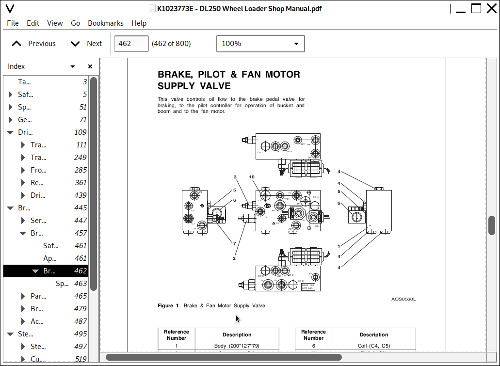
Brake, Pilot & Fan Motor Supply Valve...462
Specifications...463
Parking Brake...465
Safety Precautions...469
Applicable Models...469
General Description...470
Functional Characteristics and Maintenance Instructions for Spring Loaded Sliding Caliper Brakes...472
1. Functional Characteristics of Spring Loaded Sliding Caliper Brakes...472
2. Mounting and Basic Setting Regulations...474
3. Adjusting Regulations...475
4. Emergency Release of Parking Brake...475
5. Maintenance and Repair Work...476
Maintenance and Exchange of Brake Pads...476
Changing the Seal...477
6. General...478
Brake Pedal Valve...479
Safety Precautions...483
Applicable Models...483
General Description...484
Theory of Operation...484
Specification...486
Accumulator...487
Safety Precautions...491
Applicable Models...491
General Description...492
Specifications...494
Steering...495
Steering...497
Safety Precautions...501
Applicable Models...501
General Description...502
Power Steering System...502
EHPS Valve...504
Parts List...506
Description of operation of EHPS with integrated priority valve...507
Steering Spool at Neutral Position...508
Steering Spool Operated...509
1. Turning Left...509
2. Turning Right...510
Pressure Reducing Valves...511
Pilot Relief Valve...512
Steering Unit...513
Function...513
Exploded View of a Steering Unit...514
Function...515
Picture of Components in the EHPS...515
Cushion Valve...519
Safety Precautions...523
Applicable Models...523
Cushion Valve...524
Cushion Valve Operation...524
Function...524
Working Principle...524
Specifications...524
Parts List...525
Emergency Steering...527
Safety Precautions...531
Applicable Models...531
General Description...532
Emergency Steering Function Test...534
Emergency Steering Automatic Test...534
Pump & DC Motor...536
Frame...537
Articulation Center...539
Safety Precautions...543
Applicable Models...543
General Description...544
Maintenance Standard...545
Counterweight...547
Safety Precautions...551
Applicable Models...551
Specifications...552
Counterweight...552
Tank...553
Oil Tank...555
Safety Precautions...559
Applicable Models...559
General Description...560
Parts List...560
Specifications...561
Fuel Tank...563
Safety Precautions...567
Applicable Models...567
General Description...568
Parts List...568
Specifications...569
Fuel Sender Setting...569
Hydraulics...571
Cylinders...573
Safety Precautions...577
Applicable Models...577
General Description...578
Theory of Operation...579
Parts List...580
Bucket Hydraulic Cylinder...580
Lift Hydraulic Cylinder...582
Steering Hydraulic Cylinder...584
Troubleshooting, Testing and Adjustment...586
Disassembly...589
Cleaning and Inspection (Wear Limits and Tolerances)...591
Reassembly...591
Main Pump...599
Safety Precautions...603
Applicable Models...603
General Description...605
Theory Of Operation...605
Parts List...606
Service Kits...608
Dimensions...609
Specification...610
Model Number Code Series T6DC...610
Specifications...610
Special Tools...611
Seal Driver...611
Protective Cone...611
Disassembly...612
Reassembly...616
Main Control Valve...621
Safety Precautions...625
Applicable Models...625
General Description...626
Specifications...628
Parts List...630
Disassembly...632
Order of Replacement...632
Cleaning and Inspection (Wear Limits and Tolerances)...634
Reassembly...635
Reassembly Order...636
Valve Maintenance...638
Main Relief Valve...638
Disassembly...638
Cleaning and Inspection...638
Reassembly...639
Overload Relief Valve...640
Disassembly...640
Cleaning and Inspection...640
Reassembly...641
Anticavatation Valve...642
Disassembly...642
Cleaning and Inspection...642
Reassembly...643
Valve Adjustment...644
Main Relief Valve Adjustment...644
Overload Relief Valve Adjustment...644
Installation...645
Operation...645
Load Isolation System...647
Safety Precautions...651
Applicable Models...651
General Description...652
Over View...653
Hydraulic Circuit...654
Function...655
Maintenance and Service work...655
LIS Valve-RSM2...656
Specification...656
Characteristic Curve...656
Parts List...657
Accumulator...658
Specification...658
Parts List...658
Cooling System...659
Safety Precautions...663
Applicable Models...663
General...664
Cooling System...665
Circuit...666
Specifications...667
Checking Hydraulic Function...667
Maximum Fan Speed, Checking...668
Fan Motor...669
Cooling Fan : Bi-directional motor with speed control...670
Cooling Fan Maximum Speed...671
Time Limit of Reverse Fan Solenoid Valve...671
Proportional Pressure Relief Cartridge...671
Function...671
Proportional inverse pressure relief valve...672
Screw-in cartridge...672
Efficiency...673
Parts List...674
Solenoid Operated Spool Valve...675
Check Valve...675
Cooling Fan : Bi-directional Motor...675
Pilot System...679
Safety Precautions...683
Applicable Models...683
Overview...684
Function...685
Block Diagram...686
FNR Lever + 2 Spool Control Valve...686
FNR Lever + 3 Spool Control Valve...686
Walvoil FNR Joystick...687
Specification...687
Parts List...688
Finger-tip 2 Lever + 2 Spool Control Valve...689
Finger-tip 3 Lever + 3 Spool Control Valve...689
Finger-tip Joystick...690
Specification...690
Parts List...691
Hydraulic Schematic DL250...693
Safety Precautions...697
Applicable Models...697
DL250...699
Electrical System...700
Air Conditioner...702
Safety Precautions...706
Applicable Models...706
General Description...707
Refrigerant Circulation...709
Control Panel...711
Control Specifications...712
Temperature Level Control and Display...713
Air Discharge According to Path Selection...714
Face + Rear...714
Foot + Rear...714
Defroster + Rear...715
Airconditioning System Circuit Diagram...717
Troubleshooting...719
Refrigerant Pressure Check...719
Weight of R134a Gas Used In Machines...721
Refrigerant System Repairs...722
Refrigerant Safe Handling Procedures...722
Repair and Replacement Procedure...723
Refrigerant Recovery...725
Vacuuming Refrigerant System...725
Leakage Check...727
Refrigerant Charging...727
Inspecting System for Leakage...729
Electrical System...732
Safety Precautions...736
Applicable Models...736
Overview...737
Electric Wire Color...737
Electric Supply System...738
Engine Starting Circuit...740
Operation During Start Process...740
Operation After Start Process...743
Engine Preheating System...746
Engine Stop System...747
Charging System...748
Monitoring System...749
Instrument Panel...750
Function Check...751
Monitoring System Schematic...751
Operation...753
Instruments...753
Indicator Lights...755
Initial Operation...757
Control Unit Operation...758
Characteristic of Operation...758
Windshield Wiper...759
Front windshield wiper...759
Front Windshield Wiper Circuit...760
Rear Windshield wiper...761
Lighting System...763
Light Circuit...763
ECU System...767
ECU Electric Circuit...768
ECU System Component...769
Engine Control Unit (ECU)...769
Engine Diagnostic Connector...769
Economic Mode Switch...770
Engine Diagnostic Switch...770
Engine Warning Light...770
Electronic Accelerator...771
Engine Fault Code...772
Cooling Fan Control System...776
Outline...776
Diagram...777
Electrical Diagram...778
Parts of Cooling Fan Control System...779
Cooling Fan Controller...779
Cooling Fan Proportional Valve...779
Reverse Rotation Solenoid...779
Cooling Fan Reverse Rotation Switch...780
Reverse Rotation Lamp...780
Operation of Cooling Fan Control System...781
Communication Monitoring...781
Control of Cooling Fan...781
Self Diagnosis and Display of Cooling Fan...783
Normal Operation Display...783
Monitoring of Voltage to Controller...783
LED...783
Failure Indications and Actions...784
Emergency Steering System (Option)...785
Block Diagram...785
Emergency Steering System Components...786
Emergency Steering Timer...786
Emergency Steering Timer Connector...786
Emergency Steering Timer Circuit...787
Test Mode before Emergency Steering Start...787
Operating Character when Emergency Steering Normal Mode...788
Emergency Steering Pump...788
Emergency Steering Switch...788
Emergency Steering System Electric Circuit...789
Electric Detent System...790
Electric Circuit...790
Boom Kickout...791
Return To Dig...792
Proximity Switch...792
Electrical Schematic DL200/ DL250...794
Safety Precautions...798
Applicable Models...798
DL200/ DL250...800
Doosan Wheel Loader DL250 Repair Service Manual
![]()