
Doosan DL200, DL200TC Wheel Loaders Repair Service Manual

Complete repair service manual with Electrical Wiring Diagrams for Doosan DL200, DL200TC Wheel Loader, with workshop information to maintain, diagnose, repair, and service like professional mechanics.
Doosan DL200, DL200TC Wheel Loaders workshop service repair manual includes:
* Numbered table of contents easy to use so that you can find the information you need fast.
* Detailed sub-steps expand on repair procedure information
* Numbered instructions guide you through every repair procedure step by step.
* Troubleshooting and electrical service procedures are combined with detailed wiring diagrams for ease of use.
* Notes, cautions and warnings throughout each chapter pinpoint critical information.
* Bold figure number help you quickly match illustrations with instructions.
* Detailed illustrations, drawings and photos guide you through every procedure.
* Enlarged inset helps you identify and examine parts in detail.
MAIN SECTIONS
Safety
Wheel Loader Safety.. SP000865
Specifications
Specification for DL200/ DL200TC.. SP000914
General Maintenance
General Maintenance Procedures ... SP001055
Standard Torques .. SP000813
Drive Train
Transmission and Torque Converter... SP001011
Transmission Error Codes (ZF)... SP001056
Axle... SP001018
Drive Shaft ... SP001019
Brake
Service Brake... SP001080
Brake Supply Valve.. SP001081
Parking Brake .. SP001082
Brake Pedal Valve.. SP001083
Accumulator.. SP001084
Steering
Steering .. SP001085
Cushion Valve.. SP000328
Emergency Steering ... SP001086
Frame
Articulation Center .. SP001087
Counterweight... SP000130
Tank
Oil Tank.. SP001088
Fuel Tank... SP001089
Hydraulics
Cylinders... SP001027
Main Pump... SP001212
Main Control Valve... SP001090
Load Isolation System.. SP001091
Cooling System.. SP001092
Pilot System... SP001093
Hydraulic Schematic DL200... SP001094
Electrical System
Air Conditioner ... SP001211
Electrical System ... SP001095
Electrical Schematic DL200/ DL250.. SP000925
Total Pages: 688 pages
File Format: PDF (bookmarked, Searchable, Printable, high quality)
Language: English
Table of Contents......3
Safety......5
Wheel Loader Safety......7
Safety Precautions......11
Applicable Models......11
To the Operator of a Wheel Loader......12
Learn the Signal Words Used with the Safety Alert Symbol......14
General Safety Essentials......16
Accessory Applications......16
Location of Safety Labels......16
Unauthorized Modifications......17
General Hazard Information......17
Safety Rules......17
Safety Features......17
Inside Operator's Compartment......18
Clothing and Personal Protective Items......19
Breathing Masks, Ear Protection May Be Required......19
Vibration Level Information......19
Asbestos Dust Hazard Prevention......20
Mounting and Dismounting......20
Fuel, Oil and Hydraulic Fluid Fire Hazards......21
Precautions When Handling Fluids at High Temperature......21
Injury from Work Equipment......22
Fire Extinguisher and First Aid Kit......22
Protection from Falling or Flying Objects......23
Install Additional Safety Equipment If Conditions Require......23
Maintain Standard Safety Equipment in Good Condition......23
Attachment Precautions......24
Accumulator......24
Engine Ventilation......24
Before Starting Engine......25
Work Site Precautions......25
Checks Before Starting Engine......26
Engine Starting......27
Before Operating Machine......28
Machine Operation......29
Operate While Seated at Operator's Station ONLY......29
Seat Belts Should Be Used at All Times......29
Movement Alarms......29
Travel Precautions......30
Sloping Terrain Requires Caution......30
Avoid High Voltage Cables......31
Before Starting to Dig, Contact Authorities......31
Be Aware of Height Obstacles......31
Use Care on Loose Support......32
Use Solid Support Blocking......32
Digging Beneath Overhangs......32
Digging Beneath Wheel Loader......32
Stay Alert for People Moving Through Work Area......33
Be Aware of and Conform to Local Regulations......33
Never Use Ether Starting Aids......33
Observe General Safety Rules......34
Take Time to Provide Good Visibility......34
Keep "Pinch Point" Areas Clear Use Caution in Reverse......35
Operate Carefully on Snow and Ice and in Very Cold Temperatures......35
Parking Machine......36
Shutdown Control Functions......36
Never Let Anyone Ride on Attachment......36
Maintenance......37
Use Warning Tag During Service......37
Clean Before Inspection or Maintenance......37
Proper Tools......38
Use of Lighting......38
Fire Prevention and Explosion Prevention......38
Burn Prevention......39
Welding Repairs......40
Treatment for Electrical Welding to the Body Structure......41
Precautions for Removal, Installation, and Storage of Attachments......41
Precautions When Working on Machine......41
Lock Inspection Covers......42
Crushing Prevention and Cutting Prevention......42
Do Not Run Engine If Repairs or Work Are Being Performed Alone......42
Always Use Adequate Equipment Supports and Blocking......42
Do Not Work on Hot Engines or Hot Cooling or Hydraulic Systems......43
Hydraulic Cylinder Seals Require Periodic Replacement......43
Highpressure Hydraulic Lines Can Store a Great Deal of Energy......43
Precautions with Highpressure Line, Tubes and Hoses......44
Obtain Immediate Medical Attention if Pressurized Oil Pierces Skin......44
Use Correct Replacement Fasteners Tightened to Proper Torque......45
Safety Critical Parts Must Be Replaced Periodically......45
Dispose of All Petroleum Based Oils and Fluids Properly......45
Check Tire Pressure and Condition......45
Battery......46
Battery Hazard Prevention......46
Disconnect Batteries Before Electrical Service or Electrical Welding......46
Use Low Heat Portable Lighting......47
Boost Starting or Charging Engine Batteries......47
Towing......48
Precautions When Towing......48
Shipping and Transportation......49
Obey State and Local OvertheRoad Regulations......49
Summary of Safety Precautions for Lifting......49
Specifications......51
Specification for DL200/ DL200TC......53
Safety Precautions......57
Applicable Models......57
Component Locations......58
DL200......58
DL200TC......60
General Specifications......62
Engine Performance Curves......64
Working Range and Dimensions......66
Working Capacities......71
Bucket Capacity......71
Tipping Load......71
Material Weight......71
Approximate Weight of Workload Materials......71
General Maintenance......75
General Maintenance Procedures SP001055......77
Safety Precautions......81
Applicable Models......81
Welding Precautions and Guidelines......82
Hydraulic System General Precautions......83
Maintenance Service and Repair Procedure......85
General Precautions......85
Hydraulic System Cleanliness and Oil Leaks......86
Maintenance Precautions for Hydraulic System Service......86
Oil Leakage Precautions......87
Cleaning and Inspection......88
General Guidelines......88
Bearing inspection......89
Normal Bearing......90
Bent Cage......90
Galling......91
Abrasive Step Wear......91
Etching......92
Misalignment......92
Indentations......92
Fatigue Spalling......93
Brinelling......93
Cage Wear......93
Abrasive Roller Wear......94
Cracked Inner Race......94
Smears......94
Frettage......95
Heat Discoloration......95
Stain Discoloration......95
Standard Torques......97
Safety Precautions......101
Applicable Models......101
Torque Values for Standard Metric Fasteners......102
Torque Values for Standard U.S. Fasteners......103
Type 8 Phosphate Coated Hardware......105
Torque Values for Hose Clamps......106
Torque Values for Split Flanges......107
Torque Wrench Extension Tools......108
Torque Multiplication......108
Other Uses for Torque Wrench Extension Tools......109
Tightening Torque Specifications (Metric)......110
I. "Loctite" Fastener Adhesives......111
II. "Loctite" Pipe Thread Sealant......111
III. "Loctite" gasket/flange sealer......111
IV. "Loctite" retaining compounds......112
V. "Loctite" Adhesives......112
Drive Train......113
Transmission and Torque Converter......115
Safety Precautions......121
Applicable Models......121
General......122
Transmission and Torque Converter......124
Powershift Transmission......125
Transmission Control......125
The Chart of Measuring Points and Connection 4 WG160......127
Oil Circuit Diagram 4WG160......129
Transmission Electrical Components......132
TCU (Transmission Control Unit)......134
Transmission Control Valve......134
Transmission Oil Temperature Sensor......134
Engine Pickup Sensor......135
Central Gear Pickup Sensor......135
Turbine Pickup Sensor......135
Output Speed Sensor......136
Shift Lever Switch (DW3)......136
Forward, Reverse Switch Lever (Optional)......137
Finger Tip Work Lever......138
2-Lever (Optional)......138
3-Lever (Optional)......138
Switch Circuit......139
Auto Selector Switch......139
Display......140
Transmission Faults Codes......141
Fault Display......141
CAN Message......141
Description of Fault Codes......141
Abbreviations......142
Definition of Operation Modes......142
Normal......142
Substitute Clutch Control......142
Limphome......142
Transmission Shut Down......143
TCU Shut Down......143
Table of Fault Codes......143
Measurement of Resistance at Actuator/ sensors and Cable......143
Actuator......143
Cable......143
Transmission Electrical Circuits......144
T/M Controller Circuit......144
Traveling Circuits......145
Neutral......146
Forward First Gear......147
Forward Second Gear......148
Forward Third Gear......149
Forward Fourth Gear......150
Reverse First Gear......151
Reverse Second Gear......152
Reverse Third Gear......153
Downshift......153
Overview......153
Kickdown: Forward Second Gear to Forward First Gear (Auto Selector Switch "O" Manual Mode)......154
Downshift (Auto Selector Switch "Second Gear" Auto Mode)......155
Downshift (Auto Selector Switch "Third Gear" Auto Mode)......156
Transmission Cutoff......157
LIS (Load Isolation System) Optional......158
Aeb Starter......159
Introduction......159
Procedure to Start AEB......160
Display During AEB-mode......160
Installation View......162
Inner Section......162
Front View......164
Side View......165
Rear View......166
Special Tools......167
Engine Connection......167
Input......168
Gearbox Housing......169
Coupling......170
Coupling K1......170
Coupling K2......171
Coupling K4......172
Coupling KV......173
Coupling KR......174
Output......175
Gearshift System......176
Pressure Regulator......179
Pressure Oil Pump......180
Filter......181
Oil Pipes......182
Hydraulic Control Unit (HSG94)......183
Disassembly......185
Reassembly......188
Transmission Disassembly......193
Remove Filter Unit......193
Remove Hydraulic Control Unit (HGS-94) and Duct Plate from Gearbox Housing......194
Remove and Dismantle Converter Safety Valve......195
Engine Connection Converter......196
Hydraulic Pump......199
Converter Pressure Valve......200
Remove Output, Input and Clutches......201
Disassemble Clutch KV and KR......206
Disassemble Clutch K1, K2 and K3......209
Disassemble Clutch K4......211
Disassemble Input Shaft......212
Transmission Reassembly......213
Install Oil Tube......213
Reassemble Clutch KV and KR......217
Preassemble Plate Carrier......217
Plate Pack KV and KR......218
Reassemble Clutches K1, K2 and K3......223
Plate Pack K1, K2, and K3......224
Reassemble Clutch K4......228
Plate pack K4......229
Preassemble Input Shaft......234
Install Preassembled Output Shaft and Clutches......236
Install Output Flanges......240
Converter Pressure Valve......243
Oil Feed Housing Transmission Pump......244
Converter Safety Valve......247
Mount Duct Plate......248
Attaching Hydraulic Control Unit......248
Filter......250
Speed Sensor and Inductive Transmitters......252
Transmission Error Codes (ZF)......253
Safety Precautions......257
Applicable Models......257
Introduction......258
Abbreviations......258
Display......259
Description of Fault Codes......259
Display During Operation......260
Display During AEB-Mode......262
Definition of Operating Modes......264
Normal......264
Substitute Clutch Control......264
Limphome......264
Transmission shut Down......264
TCU Shut Down......265
Table of Fault Codes......266
Table of Fault Codes ERGOControl......285
Measurement of Resistance at Actuator/ sensors and Cable......288
Actuator......288
Cable......288
Axle......289
Safety Precautions......293
Applicable Models......293
General Description......294
Outline......294
Differential (Standard)......297
Differential Operation......297
Self Locking Differential......298
Troubleshooting......299
Special Tools......302
Clark-Hurth / Dana Axle Identification......305
Maintenance and Lubrication......306
Brake Disc......307
Wear Check and Replacement......307
Adjustment of Brake Disc Gap......308
Safety Brake......309
Adjustment of Safety Brake......313
Wheel Hub......315
Planetary Reduction Gears......319
Bevel Pinion Support (Rear Axle)......322
Self Locking Differential......328
Drive Shaft......331
Safety Precautions......335
Applicable Models......335
Drive Shaft Weight......336
Drive Shaft Coupling Dimension......336
Drive Shaft, Tightening Torque......336
Brake......337
Service Brake......339
Safety Precautions......343
Applicable Models......343
General Description......344
Service Brake System......346
When Brake Pedal Is Released......348
When Brake Pedal Is Applied......349
Accumulator Operation......350
Brake Supply Valve......351
Safety Precautions......355
Applicable Models......355
Brake, Pilot & Fan Motor Supply Valve......356
Specifications......357
Parking Brake......359
Safety Precautions......363
Applicable Models......363
General Description......364
Parking Brake......365
Front Axle Parking Brake Emergency Release......365
Applying Parking Brake......366
Releasing Parking Brake......367
Brake Pedal Valve......369
Safety Precautions......373
Applicable Models......373
General Description......374
Theory of Operation......374
Specification......376
Accumulator......377
Safety Precautions......381
Applicable Models......381
General Description......382
Specifications......384
Steering......385
Steering......387
Safety Precautions......391
Applicable Models......391
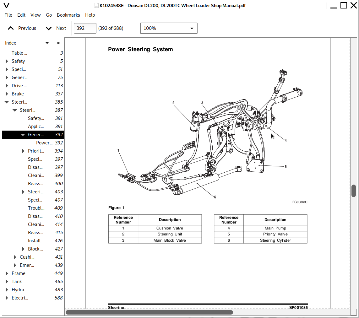
General Description......392
Power Steering System......392
Priority Valve......394
Theory of Operation......394
Parts List......396
Specifications......396
Special Tools......397
Disassembly......397
Cleaning and Inspection (Wear Limits and Tolerances)......399
Reassembly......400
Steering Unit......403
Power Steering System......403
Power Steering Unit......403
Neutral Operation......404
Right Turn......404
Left Turn......405
Gerotor Operation......405
Parts List......406
Specifications......407
Special Tools......407
Troubleshooting, Testing and Adjustment......409
Disassembly......410
Cleaning and Inspection......414
Reassembly......415
Installation......426
Block Valve......427
Theory of Operation......427
Specifications......429
Cushion Valve......431
Safety Precautions......435
Applicable Models......435
Cushion Valve......436
Cushion Valve Operation......436
Function......436
Working Principle......436
Specifications......436
Parts List......437
Emergency Steering......439
Safety Precautions......443
Applicable Models......443
General Description......444
Emergency Steering Function Test......446
Emergency Steering Automatic Test......446
Pump & DC Motor......448
Frame......449
Articulation Center......451
Safety Precautions......455
Applicable Models......455
General Description......456
Maintenance Standard......456
Counterweight......459
Safety Precautions......463
Applicable Models......463
Specifications......464
Counterweight......464
Tank......465
Oil Tank......467
Safety Precautions......471
Applicable Models......471
General Description......472
Parts List......472
Specifications......473
Fuel Tank......475
Safety Precautions......479
Applicable Models......479
General Description......480
Parts List......480
Specifications......481
Fuel Sender Setting......481
Hydraulics......483
Cylinders......485
Safety Precautions......489
Applicable Models......489
General Description......490
Theory of Operation......491
Parts List......492
Bucket Hydraulic Cylinder......492
Lift Hydraulic Cylinder......494
Steering Hydraulic Cylinder......496
Troubleshooting, Testing and Adjustment......498
Disassembly......501
Cleaning and Inspection (Wear Limits and Tolerances)......503
Reassembly......503
Main Pump......511
Safety Precautions......515
Applicable Models......515
General Description......517
Theory Of Operation......517
Parts List......518
Main Control Valve......521
Safety Precautions......525
Applicable Models......525
General Description......526
Specifications......528
Operation......529
Neutral......529
Bucket/option Spool Operation......529
Boom Spool Operation......530
Boom Float......530
Relief Valve......531
Main Relief Valve......531
Port Relief Valve......531
Operation (Main Relief Valve)......531
Operation in Inoperative State......531
Operation (A)......531
Operation (B)......532
Operation (Port Relief Valve)......532
In the Inoperative State......532
Operation (A)......532
Operation (B)......533
Operation (C)......533
Sucking Operation......533
Load Isolation System......535
Safety Precautions......539
Applicable Models......539
General Description......540
Over View......541
Hydraulic Circuit......542
Function......543
Maintenance and Service work......543
LIS Valve-RSM2......544
Specification......544
Characteristic Curve......544
Parts List......545
Accumulator......546
Specification......546
Parts List......546
Cooling System......547
Safety Precautions......551
Applicable Models......551
General......552
Cooling System......553
Circuit......554
Specifications......555
Checking Hydraulic Function......555
Maximum Fan Speed, Checking......556
Fan Motor......557
Cooling Fan : Bi-directional motor with speed control......558
Cooling Fan Maximum Speed......559
Time Limit of Reverse Fan Solenoid Valve......559
Proportional Pressure Relief Cartridge......559
Function......559
Proportional inverse pressure relief valve......560
Screw-in cartridge......560
Efficiency......561
Parts List......562
Solenoid Operated Spool Valve......563
Check Valve......563
Cooling Fan : Bi-directional Motor......563
Pilot System......567
Safety Precautions......571
Applicable Models......571
Overview......572
Function......573
Block Diagram......574
FNR Lever + 2 Spool Control Valve......574
FNR Lever + 3 Spool Control Valve......574
Walvoil FNR Joystick......575
Specification......575
Parts List......576
Finger-tip 2 Lever + 2 Spool Control Valve......577
Finger-tip 3 Lever + 3 Spool Control Valve......577
Finger-tip Joystick......578
Specification......578
Parts List......579
Hydraulic Schematic DL200......581
Safety Precautions......585
Applicable Models......585
DL200......587
Electrical System......588
Air Conditioner......590
Safety Precautions......594
Applicable Models......594
General Description......595
Refrigerant Circulation......597
Control Panel......599
Control Specifications......600
Temperature Level Control and Display......601
Air Discharge According to Path Selection......602
Face + Rear......602
Foot + Rear......602
Defroster + Rear......603
Airconditioning System Circuit Diagram......605
Troubleshooting......607
Refrigerant Pressure Check......607
Weight of R134a Gas Used In Machines......609
Refrigerant System Repairs......610
Refrigerant Safe Handling Procedures......610
Repair and Replacement Procedure......611
Refrigerant Recovery......613
Vacuuming Refrigerant System......613
Leakage Check......615
Refrigerant Charging......615
Inspecting System for Leakage......617
Electrical System......620
Safety Precautions......624
Applicable Models......624
Overview......625
Electric Wire Color......625
Electric Supply System......626
Engine Starting Circuit......628
Operation During Start Process......628
Operation After Start Process......631
Engine Preheating System......634
Engine Stop System......635
Charging System......636
Monitoring System......637
Instrument Panel......638
Function Check......639
Monitoring System Schematic......639
Operation......641
Instruments......641
Indicator Lights......643
Initial Operation......645
Control Unit Operation......646
Characteristic of Operation......646
Windshield Wiper......647
Front windshield wiper......647
Front Windshield Wiper Circuit......648
Rear Windshield wiper......649
Lighting System......651
Light Circuit......651
ECU System......655
ECU Electric Circuit......656
ECU System Component......657
Engine Control Unit (ECU)......657
Engine Diagnostic Connector......657
Economic Mode Switch......658
Engine Diagnostic Switch......658
Engine Warning Light......658
Electronic Accelerator......659
Engine Fault Code......660
Cooling Fan Control System......664
Outline......664
Diagram......665
Electrical Diagram......666
Parts of Cooling Fan Control System......667
Cooling Fan Controller......667
Cooling Fan Proportional Valve......667
Reverse Rotation Solenoid......667
Cooling Fan Reverse Rotation Switch......668
Reverse Rotation Lamp......668
Operation of Cooling Fan Control System......669
Communication Monitoring......669
Control of Cooling Fan......669
Self Diagnosis and Display of Cooling Fan......671
Normal Operation Display......671
Monitoring of Voltage to Controller......671
LED......671
Failure Indications and Actions......672
Emergency Steering System (Option)......673
Block Diagram......673
Emergency Steering System Components......674
Emergency Steering Timer......674
Emergency Steering Timer Connector......674
Emergency Steering Timer Circuit......675
Test Mode before Emergency Steering Start......675
Operating Character when Emergency Steering Normal Mode......676
Emergency Steering Pump......676
Emergency Steering Switch......676
Emergency Steering System Electric Circuit......677
Electric Detent System......678
Electric Circuit......678
Boom Kickout......679
Return To Dig......680
Proximity Switch......680
Electrical Schematic DL200/ DL250......682
Safety Precautions......686
Applicable Models......686
DL200/ DL250......688
Doosan DL200, DL200TC Wheel Loaders Repair Service Manual
![]()