
John Deere 1775NT 24-Row Planter with MaxEmerge 5 Row Units Diagnosis and Tests Service Technical Manual (TM131619)

Complete Diagnosis & Tests Technical Manual with electrical wiring diagrams for John Deere 1775NT 24-Row Planter with MaxEmerge 5 Row Units (SN.760100-), with all the workshop information to maintain, diagnose, repair, and rebuild like professional mechanics.
John Deere 24-Row Planter with MaxEmerge 5 Row Units Models 1775NT workshop Diagnosis & Tests technical manual includes:
* Numbered table of contents easy to use so that you can find the information you need fast.
* Detailed sub-steps expand on repair procedure information
* Numbered instructions guide you through every repair procedure step by step.
* Troubleshooting and electrical service procedures are combined with detailed wiring diagrams for ease of use.
* Notes, cautions and warnings throughout each chapter pinpoint critical information.
* Bold figure number help you quickly match illustrations with instructions.
* Detailed illustrations, drawings and photos guide you through every procedure.
* Enlarged inset helps you identify and examine parts in detail.
tm131619 - 1775NT 24-Row Planter with MaxEmerge 5 Row Units Diagnosis and Tests (SN XXXXXX - 770100) Technical Manual.pdf
tm131619 - 1775NT 24-Row Planter with MaxEmerge 5 Row Units Diagnosis and Tests (SN XXXXXX - 770100) Technical Manual.epub
Total Pages: 1,884 pages
File Format: PDF/EPUB/MOBI/AZW (PC/Mac/Android/Kindle/iPhone/iPad; bookmarked, ToC, Searchable, Printable)
Language: English
MAIN SECTIONS
Diagnostic Manual
Foreword
General Information
Acronym Table
How to Use This Manual
Safety
Lubricants
Recommended Tools for Diagnostics
Basic Diagnostics
Diagnostic Information for Electrical Components
Diagnostic Information for Hydraulic Components
Maintaining Hydraulic Systems and Components
Standard Torque Chart Procedures
Diagnostic Trouble Codes
Accessing Diagnostic Trouble Codes
Planter Main 1 (PM1)
Planter Main 2 (PM2)
Observable Symptoms and System Diagnostics
Observable Symptoms
Electrical
General Information
Theory of Operation
Schematics
Diagnostics
Electronic Control Units
Accessing Diagnostic Addresses
Diagnostic Addresses by Control Unit
Diagnostics
Electrical Connectors
Electrical Assemblies
Sensors
Lights
Fuses
Charging
Relays
Motors
Switches
Diodes
Interconnects
Electronically Actuated Mechanical Devices
Hydraulics
Theory of Operation
Schematics
Diagnostics
Hydraulic Component Information
Accumulator
Sensor or Gauge
Cylinder, Actuator, or Piston
Check Valve
Filter
Valve Block, Assembly, or Gearcase
Cooler
Motor
Orifice
Reservoir Tank
Valve
Diagnostic Receptacle or Coupler
Solenoid Valve
Pneumatics
Theory of Operation
Schematics
Diagnostics
Pneumatic Components
Accumulators
Sensors
Check Valves
Filters
Assembly Groups
Pumps
Reservoirs
Switches
Valves
Couplers or Diagnostic Receptacles
Solenoid Valves
TABLE OF CONTENTS......1
Section 210: General Information......462
Group 10: Acronym Table......37
Acronym Table......37
Group 5A: How to Use This Manual......33
Information is Available in Sections, Groups and Subgroups......39
Group 5B: Safety......33
Work In Ventilated Area......41
Recognize Safety Information......42
Avoid Backover Accidents......43
Prevent Machine Runaway......44
Avoid Contact with Agricultural Chemicals......45
Clean Vehicle of Hazardous Pesticides......47
Use a Safety Chain......48
Work in Clean Area......49
Decommissioning — Proper Recycling and Disposal of Fluids and Components......50
Prepare for Emergencies......51
In Case of Fire......52
Use Safety Lights and Devices......53
Avoid High-Pressure Fluids......54
Use Proper Lifting Equipment......55
Illuminate Work Area Safely......56
Live With Safety......57
Support Machine Properly......58
Freeing a Mired Machine......59
Protect Against Noise......60
Remove Paint Before Welding or Heating......61
Park Machine Safely......62
Prevent Acid Burns......63
Follow Safety Instructions......65
Use Proper Tools......66
Keep Riders Off Machine......67
Service Tires Safely......68
Stay Clear of Rotating Drivelines......69
Construct Dealer-Made Tools Safely......70
Practice Safe Maintenance......71
Understand Signal Words......72
Replace Safety Signs......73
Prevent Battery Explosions......74
Protect Against High Pressure Spray......75
Avoid Heating Near Pressurized Fluid Lines......76
Tow Loads Safely......77
Transport Towed Equipment at Safe Speeds......78
Observe Maximum Transport Speed......80
Wear Protective Clothing......81
Precautions for Welding......82
Handle Agricultural Chemicals Safely......84
Service and Operate Chemical Sprayers Safely......86
Relieve Hydraulic Pressure Safely......88
Use Steps and Handholds Correctly......89
Group 5C: Lubricants......34
Grease......91
Gear Oil......92
Alternative and Synthetic Lubricants......93
Lubricant Storage......94
Group 5D: Recommended Tools for Diagnostics......34
Recommended Tools......97
Group 5E: Diagnostic Philosophy......34
Basic Diagnostic Philosophy......102
Systematic Diagnostic Approach Overview......105
Troubleshooting Unresolved Problems......109
Group 5F: Diagnostic Information for Electrical Components......34
Electrical Designators......111
Visually Inspect Electrical System......112
Group 5G: Diagnostic Information for Hydraulic Components......120
Hydraulic Designators......115
Troubleshooting Tips......116
Visually Inspect Hydraulic System......117
Group 5H: Maintaining Hydraulic Systems and Components......35
Hydraulic Components......120
Oil Storage and Filling......121
Oil Filtration......122
Group 5I: Standard Torque Chart Procedures......35
Unified Inch Bolt and Screw Torque Values......126
Metric Bolt and Screw Torque Values......129
Section 211: Diagnostic Trouble Codes......131
Group 10A: Accessing Diagnostic Trouble Codes......141
Accessing Diagnostic Trouble Codes......141
Group 10B: Closing Wheel Controller (CWC) Codes......131
CWC 001351.14 - Air Supply System......131
CWC 001387.00 - System control disabled......131
CWC 001387.01 - System control disabled......131
CWC 001387.03 - Closing Wheel Control System......131
CWC 001387.04 - Closing Wheel Control System......131
CWC 001387.10 - System control disabled......131
CWC 001387.13 - Closing Wheel Control System......131
CWC 001387.14 - Closing Wheel Control System......131
CWC 001387.16 - Pressure too high on Closing Wheel Group 1......131
CWC 001387.17 - Moderate leak detected on Closing Wheel Group 1......131
CWC 001388.00 - System control disabled......131
CWC 001388.01 - System control disabled......131
CWC 001388.03 - Closing Wheel Control System......131
CWC 001388.04 - Closing Wheel Control System......131
CWC 001388.10 - System control disabled......131
CWC 001388.13 - Closing Wheel Control System......131
CWC 001388.14 - Closing Wheel Control System......131
CWC 001388.16 - Pressure too high on Closing Wheel Group 2......131
CWC 001388.17 - Moderate leak detected on Closing Wheel Group 2......131
CWC 003509.03 - Sensor Voltage is above Normal......131
CWC 003509.04 - Sensor Voltage is below Normal......131
CWC 517151.01 - Closing Wheel Control System......131
CWC 517151.03 - Closing Wheel Control System......131
CWC 517151.04 - Closing Wheel Control System......131
CWC 517151.05 - Closing Wheel Control System......131
CWC 517151.06 - Closing Wheel Control System......131
CWC 517151.12 - Closing Wheel Control System......131
CWC 517152.03 - Closing Wheel Control System......131
CWC 517152.04 - Closing Wheel Control System......131
CWC 517152.12 - Closing Wheel Control System......132
CWC 517153.01 - Closing Wheel Control System......132
CWC 517153.03 - Closing Wheel Control System......132
CWC 517153.04 - Closing Wheel Control System......132
CWC 517153.05 - Closing Wheel Control System......132
CWC 517153.06 - Closing Wheel Control System......132
CWC 517153.12 - Closing Wheel Control System......132
CWC 517154.03 - Closing Wheel Control System......132
CWC 517154.04 - Closing Wheel Control System......132
CWC 517154.12 - Closing Wheel Control System......132
CWC 517154.31 - Closing Wheel Control System......132
520463.03 - Closing Wheel Control ECU Power......132
520463.04 - Closing Wheel Control ECU Power......132
523218.03 - Valve Power 2 Voltage Above Normal......132
523218.04 - Closing Wheel Control Valve Power 2......132
523218.05 - Closing Wheel Control Valve Power 2......132
CWC 523438.02 - EEPROM Checksum Error......132
CWC 523438.14 - EEPROM Out of Bounds Error......132
Group 10C: Planter Main 1 (PM1)......132
PM1 000084.09 - Wheel Speed Not Detected on CAN Bus......132
PM1 000609.12 - Planter Module 2 Not Responding......132
PM1 000629.14 - Planter Disabled, Cycle Power......132
PM1 001859.09 - Radar Speed Not Detected On CAN Bus......132
PM1 001859.10 - Ground Speed and Tractor Speed Conflict......132
PM1 001859.14 - Minimum Speed Not Reached At End Of Quickstart......132
PM1 003132.00 - Fertilizer Pressure 1 High......132
PM1 003132.03 - Fertilizer Sensor 1 Voltage High......132
PM1 003132.04 - Fertilizer Sensor 1 Voltage Low......132
PM1 003509.03 - 5 Volt Sensor Supply Voltage High......132
PM1 003509.04 - 5 Volt Sensor Supply Voltage Low......132
PM1 003510.03 - 8 Volt Sensor Supply Voltage High......132
PM1 003510.04 - 8 Volt Sensor Supply Voltage Low......132
PM1 005109.12 - Planter Module 3 Not Responding......132
PM1 005117.01 - EPM 1 Input Voltage Low......133
PM1 005117.02 - EPM 1 Not Responding To Setup......133
PM1 005117.12 - EPM 1 Offline......133
PM1 005117.18 - EPM 1 Low Voltage On Inputs......133
PM1 005118.01 - EPM 2 Input Voltage Low......133
PM1 005118.02 - EPM 2 Not Responding To Setup......133
PM1 005118.12 - EPM 2 Offline......133
PM1 005118.18 - EPM 2 Low Voltage On Inputs......133
PM1 005119.01 - EPM 3 Input Voltage Low......133
PM1 005119.02 - EPM 3 Not Responding To Setup......133
PM1 005119.12 - EPM 3 Offline......133
PM1 005119.18 - EPM 3 Low Voltage On Inputs......133
PM1 520328.02 - Seed Detected On Row 1 While Deactivated......133
PM1 520328.12 - Row 1 Clutch Failed......133
PM1 521037.03 - Vacuum 1 Sensor Voltage High......133
PM1 521037.04 - Vacuum 1 Sensor Voltage Low......133
PM1 521037.17 - Vacuum 1 Pressure Low......133
PM1 521124.03 - Vacuum 2 Sensor Voltage High......133
PM1 521124.04 - Vacuum 2 Sensor Voltage Low......133
PM1 521124.17 - Vacuum 2 Pressure Low......133
PM1 521529.00 - Fertilizer Pressure 2 High......133
PM1 521529.03 - Fertilizer Sensor 2 Voltage High......133
PM1 521529.04 - Fertilizer Sensor 2 Voltage Low......133
PM1 521633.07 - VRD 1 Frequency Low......133
PM1 521633.10 - VRD 1 Frequency Abnormal......133
PM1 521726.07 - VRD 2 Frequency Low......133
PM1 521726.10 - VRD 2 Frequency Abnormal......133
PM1 522260.02 - Motion Sensor Speed and Tractor Speed Conflict......133
PM1 522260.10 - Motion Sensor Responding When No Active Tractor Speed......133
PM1 522328.02 - Seed Detected On Row 24 While Deactivated......133
PM1 522328.12 - Row 24 Clutch Failed......133
PM1 522329.02 - Seed Detected On Row 23 While Deactivated......133
PM1 522329.12 - Row 23 Clutch Failed......133
PM1 522330.02 - Seed Detected On Row 22 While Deactivated......134
PM1 522330.12 - Row 22 Clutch Failed......134
PM1 522331.02 - Seed Detected On Row 21 While Deactivated......134
PM1 522331.12 - Row 21 Clutch Failed......134
PM1 522332.02 - Seed Detected On Row 20 While Deactivated......134
PM1 522332.12 - Row 20 Clutch Failed......134
PM1 522333.02 - Seed Detected On Row 19 While Deactivated......134
PM1 522333.12 - Row 19 Clutch Failed......134
PM1 522334.02 - Seed Detected On Row 18 While Deactivated......134
PM1 522334.12 - Row 18 Clutch Failed......134
PM1 522335.02 - Seed Detected On Row 17 While Deactivated......134
PM1 522335.12 - Row 17 Clutch Failed......134
PM1 522336.02 - Seed Detected On Row 16 While Deactivated......134
PM1 522336.12 - Row 16 Clutch Failed......134
PM1 522337.02 - Seed Detected On Row 15 While Deactivated......134
PM1 522337.12 - Row 15 Clutch Failed......134
PM1 522338.02 - Seed Detected On Row 14 While Deactivated......134
PM1 522338.12 - Row 14 Clutch Failed......134
PM1 522339.02 - Seed Detected On Row 13 While Deactivated......134
PM1 522339.12 - Row 13 Clutch Failed......134
PM1 522342.02 - Seed Detected On Row 12 While Deactivated......134
PM1 522342.12 - Row 12 Clutch Failed......134
PM1 522346.02 - Seed Detected On Row 11 While Deactivated......134
PM1 522346.12 - Row 11 Clutch Failed......134
PM1 522347.02 - Seed Detected On Row 10 While Deactivated......134
PM1 522347.12 - Row 10 Clutch Failed......134
PM1 522348.02 - Seed Detected On Row 9 While Deactivated......134
PM1 522348.12 - Row 9 Clutch Failed......134
PM1 522349.02 - Seed Detected On Row 8 While Deactivated......134
PM1 522349.12 - Row 8 Clutch Failed......134
PM1 522351.02 - Seed Detected On Row 7 While Deactivated......134
PM1 522351.12 - Row 7 Clutch Failed......134
PM1 522352.02 - Seed Detected On Row 6 While Deactivated......134
PM1 522352.12 - Row 6 Clutch Failed......135
PM1 522353.02 - Seed Detected On Row 5 While Deactivated......135
PM1 522353.12 - Row 5 Clutch Failed......135
PM1 522354.02 - Seed Detected On Row 4 While Deactivated......135
PM1 522354.12 - Row 4 Clutch Failed......135
PM1 522355.02 - Seed Detected On Row 3 While Deactivated......135
PM1 522355.12 - Row 3 Clutch Failed......135
PM1 522356.02 - Seed Detected On Row 2 While Deactivated......135
PM1 522356.12 - Row 2 Clutch Failed......135
PM1 522941.11 - Selected Ground Speed Source is Wheel......135
PM1 522941.14 - Selected Ground Speed Source is Manual......135
PM1 522942.09 - Planting Parameters Satisfied Before Controller Initialized......135
PM1 523111.14 - Reset System Parameters......135
PM1 523161.31 - Row 24 Seed Sensor Not Responding......135
PM1 523163.31 - Row 23 Seed Sensor Not Responding......135
PM1 523164.31 - Row 22 Seed Sensor Not Responding......135
PM1 523165.31 - Row 21 Seed Sensor Not Responding......135
PM1 523166.31 - Row 20 Seed Sensor Not Responding......135
PM1 523167.31 - Row 19 Seed Sensor Not Responding......135
PM1 523168.31 - Row 18 Seed Sensor Not Responding......135
PM1 523169.31 - Row 17 Seed Sensor Not Responding......135
PM1 523170.31 - Row 16 Seed Sensor Not Responding......135
PM1 523171.31 - Row 15 Seed Sensor Not Responding......135
PM1 523172.31 - Row 14 Seed Sensor Not Responding......135
PM1 523173.31 - Row 13 Seed Sensor Not Responding......135
PM1 523174.31 - Row 12 Seed Sensor Not Responding......135
PM1 523175.31 - Row 11 Seed Sensor Not Responding......135
PM1 523176.31 - Row 10 Seed Sensor Not Responding......135
PM1 523177.31 - Row 9 Seed Sensor Not Responding......135
PM1 523178.31 - Row 8 Seed Sensor Not Responding......135
PM1 523179.31 - Row 7 Seed Sensor Not Responding......135
PM1 523180.31 - Row 6 Seed Sensor Not Responding......135
PM1 523181.31 - Row 5 Seed Sensor Not Responding......135
PM1 523182.31 - Row 4 Seed Sensor Not Responding......136
PM1 523183.31 - Row 3 Seed Sensor Not Responding......136
PM1 523184.31 - Row 2 Seed Sensor Not Responding......136
PM1 523185.31 - Row 1 Seed Sensor Not Responding......136
PM1 523194.31 - Rows Not Planting......136
PM1 523319.03 - ECU Power Voltage High......136
PM1 523319.04 - ECU Power Voltage Low......136
PM1 523328.11 - Height Sensor Not Calibrated......136
PM1 523328.14 - Height Sensor Below Normal Operating Range......136
PM1 523436.31 - Watchdog Reset For Seed Monitor......136
PM1 523651.11 - Internal Stack Overflow......136
PM1 523652.03 - High Current Power Voltage High......136
PM1 523652.04 - High Current Power Voltage Low......136
PM1 523705.31 - Watchdog Reset For Seed Monitor And VRD......136
PM1 523773.03 - CAN High Voltage High......136
PM1 523773.04 - CAN High Voltage Low......136
PM1 523774.03 - CAN Low Voltage High......136
PM1 523774.04 - CAN Low Voltage Low......136
PM1 524054.14 - Specified Area Has Been Planted......136
PM1 524055.11 - Stored NOVRAM Value Abnormal......136
Group 10D: Planter Main 2 (PM2)......136
PM2 000609.02 - Seed Monitor Not Responding......136
PM2 000609.12 - Seed Monitor Offline......136
PM2 000629.12 - Watchdog Timed Out......136
PM2 000639.12 - Implement CAN Bus Lost Message......136
PM2 000639.14 - Implement CAN Bus Excessive Errors......136
PM2 000705.13 - Node 1 Sensor Calibration Error......136
PM2 000705.19 - Node 1 Downforce Sensor Error......136
PM2 000706.13 - Node 2 Sensor Calibration Error......136
PM2 000706.19 - Node 2 Downforce Sensor Error......136
PM2 000707.13 - Node 3 Sensor Calibration Error......136
PM2 000707.19 - Node 3 Downforce Sensor Error......136
PM2 000708.13 - Node 4 Sensor Calibration Error......136
PM2 000708.19 - Node 4 Downforce Sensor Error......137
PM2 000709.13 - Node 5 Sensor Calibration Error......137
PM2 000709.19 - Node 5 Downforce Sensor Error......137
PM2 001231.12 - Left CAN Bus Lost Message......137
PM2 001231.14 - Left CAN Bus Excessive Errors......137
PM2 001235.12 - Right CAN Bus Lost Message......137
PM2 001235.14 - Right CAN Bus Excessive Errors......137
PM2 001351.14 - Compressor Motor Time Limit Exceeded......137
PM2 003509.03 - 5 Volt Sensor Supply Voltage High......137
PM2 003509.04 - 5 Volt Sensor Supply Voltage Low......137
PM2 005111.02 - Node 1 Message Missing......137
PM2 005111.12 - Node 1 Missing......137
PM2 005111.19 - Node 1 Accelerometer Fault......137
PM2 005112.02 - Node 2 Message Missing......137
PM2 005112.12 - Node 2 Missing......137
PM2 005112.19 - Node 2 Accelerometer Fault......137
PM2 005113.02 - Node 3 Message Missing......137
PM2 005113.12 - Node 3 Missing......137
PM2 005113.19 - Node 3 Accelerometer Fault......137
PM2 005114.02 - Node 4 Message Missing......137
PM2 005114.12 - Node 4 Missing......137
PM2 005114.19 - Node 4 Accelerometer Fault......137
PM2 005115.02 - Node 5 Message Missing......137
PM2 005115.12 - Node 5 Missing......137
PM2 005115.19 - Node 5 Accelerometer Fault......137
PM2 521087.03 - Increase Solenoid Feedback Voltage High......137
PM2 521087.05 - Increase Solenoid Current Low......137
PM2 521087.06 - Increase Solenoid Current High......137
PM2 521092.03 - Exhaust Solenoid Feedback Voltage High......137
PM2 521092.05 - Exhaust Solenoid Current Low......137
PM2 521092.06 - Exhaust Solenoid Current High......137
PM2 521130.03 - Row Unit Downforce Sensor Signal Voltage High......137
PM2 521130.06 - Row Unit Downforce Sensor Signal Voltage Low......137
PM2 521130.13 - Row Unit Downforce Sensor Zero Error......138
PM2 521938.03 - Right Address Feedback Voltage High......138
PM2 521938.05 - Right Address Line Open......138
PM2 521938.06 - Right Address Current High......138
PM2 521939.03 - Row Unit Downforce Sensor Signal Voltage High......138
PM2 521939.06 - Row Unit Downforce Sensor Signal Voltage Low......138
PM2 521939.13 - Row Unit Downforce Sensor Zero Error......138
PM2 521940.03 - Exhaust Solenoid Feedback Voltage High......138
PM2 521940.05 - Exhaust Solenoid Current Low......138
PM2 521940.06 - Exhaust Solenoid Current High......138
PM2 521941.03 - Increase Solenoid Feedback Voltage High......138
PM2 521941.05 - Increase Solenoid Current Low......138
PM2 521941.06 - Increase Solenoid Current High......138
PM2 523219.03 - High Current Power Voltage High......138
PM2 523219.04 - High Current Power Voltage Low......138
PM2 523219.05 - High Current Power Not Detected......138
PM2 523319.03 - ECU Power Voltage High......138
PM2 523319.04 - ECU Power Voltage Low......138
PM2 523685.03 - Left Address Feedback Voltage High......138
PM2 523685.05 - Left Address Line Open......138
PM2 523685.06 - Left Address Current High......138
Section 212: Observable Symptoms and System Diagnostics......392
Group 10: Observable Symptoms......392
Auxiliary Hydraulics Observable Symptoms......395
Auxiliary Power Observable Symptoms......396
CAN Bus Observable Symptoms......397
CCS Agitator Observable Symptoms......399
CCS Blower Observable Symptoms......400
CCS Tank Low Warning Observable Symptoms......402
Drawbar Hitch Observable Symptoms......403
Electronic Control Unit (ECU) Power and Ground Observable Symptoms......404
Enhanced Monitoring Observable Symptoms......405
Fertilizer Disconnects Observable Symptoms......406
Fertilizer Pressure Observable Symptoms......407
Field Lift Observable Symptoms......408
Fold Observable Symptoms......410
Frame Control Console Observable Symptoms......412
Frame Weight Distribution Observable Symptoms......413
Ground Drive Disconnects Observable Symptoms......414
Height Sensor Observable Symptoms......415
High Current Power and Ground Observable Symptoms......416
Implement Receiver Observable Symptoms......417
Insecticide Disconnects Observable Symptoms......418
Lighting - CCS Fill Lights Observable Symptoms......419
Lighting - Transport Lights Observable Symptoms......421
Markers Observable Symptoms......423
Pneumatic Closing Wheels Observable Symptoms......425
Pneumatic Downforce Observable Symptoms......427
Population Observable Symptoms......430
Rate Controller Observable Symptoms......432
Row Command Observable Symptoms......434
Seed Monitoring Observable Symptoms......436
SeedStar Mobile Observable Symptoms......438
Transport Lift Observable Symptoms......440
Vacuum Observable Symptoms......442
Variable Rate Drive Observable Symptoms......443
Variable Rate Fertilizer Observable Symptoms......446
Winglets Observable Symptoms......447
Section 240: Electrical......448
Group 05: General Information......462
General Information......462
Intermittent Fault Diagnostics......472
Solenoid Sequence Table......473
Circuit Load Test......474
Group 20: Theory of Operation......448
Auxiliary Hydraulics Electrical Theory of Operation......478
Auxiliary Power Electrical Theory of Operation......479
CAN Bus Electrical Theory of Operation......480
CCS Agitator Electrical Theory of Operation......481
CCS Blower Electrical Theory of Operation......482
CCS Tank Low Warning Electrical Theory of Operation......483
Drawbar Hitch Electrical Theory of Operation......484
Electronic Control Unit (ECU) Power and Ground Electrical Theory of Operation......485
Enhanced Monitoring Electrical Theory of Operation......486
Fertilizer Disconnects Electrical Theory of Operation......487
Fertilizer Pressure Electrical Theory of Operation......488
Field Lift Electrical Theory of Operation......489
Fold Electrical Theory of Operation......490
Frame Control Console Electrical Theory of Operation......492
Frame Weight Distribution Electrical Theory of Operation......494
Ground Drive Disconnects Electrical Theory of Operation......495
Height Sensor Electrical Theory of Operation......496
High Current Power and Ground Electrical Theory of Operation......497
Implement Receiver Electrical Theory of Operation......498
Insecticide Disconnects Electrical Theory of Operation......499
Lighting - CCS Fill Lights Electrical Theory of Operation......500
Lighting - Transport Lights (EU) Electrical Theory of Operation......501
Lighting - Transport Lights (NA) Electrical Theory of Operation......502
Markers Electrical Theory of Operation......504
Pneumatic Closing Wheels Electrical Theory of Operation......506
Pneumatic Downforce Electrical Theory of Operation......508
Rate Controller Electrical Theory of Operation......511
Row Command Electrical Theory of Operation......512
Seed Monitoring Electrical Theory of Operation......513
SeedStar Mobile Electrical Theory of Operation......514
Transport Lift Electrical Theory of Operation......516
Vacuum Electrical Theory of Operation......517
Variable Rate Drive Electrical Theory of Operation......518
Variable Rate Fertilizer Electrical Theory of Operation......519
Winglets Electrical Theory of Operation......521
Group 30: Schematics......449
Auxiliary Hydraulics Electrical Schematic......524
Auxiliary Power Electrical Schematic......526
CAN Bus Electrical Schematic......528
CCS Agitator Electrical Schematic......532
CCS Blower Electrical Schematic......534
CCS Tank Low Warning Electrical Schematic......536
Drawbar Hitch Electrical Schematic......538
Electronic Control Unit (ECU) Power and Ground Electrical Schematic......540
Enhanced Monitoring Electrical Schematic......543
Fertilizer Disconnects Electrical Schematic......546
Fertilizer Pressure Electrical Schematic......548
Field Lift Electrical Schematic......550
Fold Electrical Schematic......552
Frame Control Console Electrical Schematic......554
Frame Weight Distribution Electrical Schematic......556
Ground Drive Disconnects Electrical Schematic......558
Height Sensor Electrical Schematic......560
High Current Power and Ground Electrical Schematic......562
Implement Receiver Electrical Schematic......565
Insecticide Disconnects Electrical Schematic......567
Lighting - CCS Fill Lights Electrical Schematic......569
Lighting - Transport Lights Identification......570
Lighting - Transport Lights (EU) Electrical Schematic......571
Lighting - Transport Lights (NA) Electrical Schematic......573
Markers Electrical Schematic......576
Pneumatic Closing Wheels Electrical Schematic......578
Pneumatic Downforce Electrical Schematic......580
Rate Controller Electrical Schematic......583
Row Command Electrical Schematic......585
Seed Monitoring Electrical Schematic......587
SeedStar Mobile Electrical Schematic......588
Transport Lift Electrical Schematic......589
Vacuum Electrical Schematic......591
Variable Rate Drive Electrical Schematic......593
Variable Rate Fertilizer Electrical Schematic......595
Winglets Electrical Schematic......596
Group 50: Diagnostics......450
Auxiliary Hydraulics Electrical Diagnostic......600
Auxiliary Power Electrical Diagnostic......602
CAN Bus Electrical Diagnostic......607
CCS Agitator Electrical Diagnostic......617
CCS Blower Electrical Diagnostic......622
CCS Tank Low Warning Electrical Diagnostic......627
Disconnects Electrical Diagnostic......631
Electric Compressor Diagnostic......640
Electronic Control Unit (ECU) Power and Ground Electrical Diagnostic......650
Enhanced Monitoring Electrical Diagnostic......661
Fertilizer Pressure Electrical Diagnostic......673
Field Lift Electrical Diagnostic......677
Fold Electrical Diagnostic......685
Frame Control Console Electrical Diagnostic......695
Frame Weight Distribution Electrical Diagnostic......715
Height Sensor Electrical Diagnostic......720
High Current Power and Ground Electrical Diagnostic......724
Implement Receiver Electrical Diagnostic......733
Lighting - Transport Lights (EU) Electrical Diagnostic......739
Lighting - Transport Lights (NA) Electrical Diagnostic......748
Markers Electrical Diagnostic......761
Pneumatic Closing Wheels Electrical Diagnostic......779
Pneumatic Downforce Electrical Diagnostic......789
Rate Controller Electrical Diagnostic......801
Row Command Electrical Diagnostic......812
Seed Monitoring Electrical Diagnostic......817
SeedStar Mobile Electrical Diagnostic......828
Transport Lift Electrical Diagnostic......840
Vacuum Electrical Diagnostic......848
Variable Rate Drive Electrical Diagnostic......852
Variable Rate Fertilizer Electrical Diagnostic......860
Winglets Electrical Diagnostic......869
Section 245: Electronic Control Units......877
Group 10A: Accessing Diagnostic Addresses......880
Accessing Diagnostic Addresses......880
Group 10B: Diagnostic Addresses by Control Unit......877
Planter Main 1 (PM1) Addresses......890
Planter Main 2 (PM2) Addresses......898
Group 50: Diagnostics......877
Closing Wheel Controller (CWC) Test......908
Planter Main 1 (PM1) Control Unit Test......912
Planter Main 2 (PM2) Control Unit Test......917
Electronic Power Module (EPM) 1 Diagnostic Test......922
Electronic Power Module (EPM) 2 Diagnostic Test......928
Electronic Power Module (EPM) 3 Diagnostic Test......933
Variable Rate Fertilizer (VRF) Control Unit Test......938
Wireless Data Server (WDS) Test......944
Section 249: Electrical Connectors......951
Group 40A: Electrical Assemblies......951
XA4 — Flasher Module Connector......961
XA7 — Frame Control Console Connector......963
XA8-1 — Rate Controller J1 Connector......965
XA8-2 — Rate Controller J2 Connector......968
XA8-3 — Rate Controller J3 Connector......972
XA9 — Implement Receiver Connector......975
XA10 — Implement CAN Bus Secondary Terminator Connector......977
XA11-A — Planter Main 1 (PM1) Control Unit A1 Connector......979
XA11-B — Planter Main 1 (PM1) Control Unit B Connector......982
XA12-1 — Planter Main 2 (PM2) Control Unit J1 Connector......985
XA12-2 — Planter Main 2 (PM2) Control Unit J2 Connector......989
XA12-3 — Planter Main 2 (PM2) Control Unit J3 Connector......993
XA12-4 — Planter Main 2 (PM2) Control Unit MMC Power Connector......997
XA15 — Left CAN Bus Primary Terminator Connector......999
XA15E — Left CAN IN Interconnect......1001
XA16 — Left CAN Bus Secondary Terminator Connector......1003
XA16E — Right CAN IN Interconnect......1005
XA17 — Left CAN Bus Diagnostic Plug......1007
XA18 — Right CAN Bus Primary Terminator Connector......1009
XA19 — Right CAN Bus Secondary Terminator Connector......1011
XA20 — Right CAN Bus Diagnostic Plug......1013
XA21-1 — EPM 1 - J1 Connector......1015
XA21-2 — EPM 1 - J2 Connector......1017
XA21-3 — EPM 1 - J3 Connector......1019
XA22-1 — EPM 2 - J1 Connector......1021
XA22-2 — EPM 2 - J2 Connector......1023
XA22-3 — EPM 2 - J3 Connector......1025
XA23-1 — EPM 3 - J1 Connector......1027
XA23-2 — EPM 3 - J2 Connector......1029
XA23-3 — EPM 3 - J3 Connector......1031
XA31 — Node 1 Connector......1033
XA32 — Node 2 Connector......1036
XA33 — Node 3 Connector......1039
XA34 — Node 4 Connector......1042
XA35 — Node 5 Connector......1045
XA70-1 — Closing Wheel Controller J1 Connector......1048
XA70-2 — Closing Wheel Controller J2 Connector......1052
XA80-1 — Variable Rate Fertilizer 30-pin Connector......1056
XA80-2 — Variable Rate Fertilizer 18-pin Connector......1059
XA90 — Wireless Data Server (WDS) Connector......1061
XA90-2 — SeedStar Mobile Antenna Connector......1063
XA91-1 — Seed Controller 1 J1 Connector......1065
XA91-2 — Seed Controller 1 J2 Connector......1068
XA91-3 — Seed Controller 1 J3 Connector......1072
XA95-A — Junction Box 1 A Connector......1075
XA95-B — Junction Box 1 B Connector......1078
Group 40B: Sensors......952
XB1 — Height Sensor Connector......1083
XB2 — Motion Sensor Connector......1085
XB31 — Gauge Wheel Load Sensor 1 Connector......1087
XB32 — Gauge Wheel Load Sensor 2 Connector......1090
XB33 — Gauge Wheel Load Sensor 3 Connector......1093
XB34 — Gauge Wheel Load Sensor 4 Connector......1096
XB35 — Gauge Wheel Load Sensor 5 Connector......1099
XB43 — Left Bin Level Sensor Connector......1102
XB44 — Right Bin Level Sensor Connector......1104
XB45 — Front Bin Level Sensor Connector......1106
XB51 — VRD 1 Speed Sensor Connector......1108
XB52 — VRD 2 Speed Sensor Connector......1110
XB61 — Vacuum 1 Pressure Sensor Connector......1112
XB62 — Vacuum 2 Pressure Sensor Connector......1114
XB71 — Air Spring Pressure Sensor Connector......1116
XB76 — Pressure Sensor 6 Connector......1119
XB77 — Pressure Sensor 7 Connector......1121
XB81 — Fertilizer Pressure Sensor 1 Connector......1123
XB81P — Fertilizer Pump 1 Position Sensor Connector......1125
XB81S — Fertilizer Pump 1 Speed Sensor Connector......1127
XB82 — Fertilizer Pressure Sensor 2 Connector......1129
XB82P — Fertilizer Pump 2 Position Sensor Connector......1131
XB82S — Fertilizer Pump 2 Speed Sensor Connector......1133
XB101-XB124 — Seed Sensor Connectors......1135
Group 40E: Lights......953
XE1 — Left Amber Light (NA) Connector......1139
XE2 — Left Red Light (NA) Connector......1141
XE3 — Right Red Light (NA) Connector......1143
XE4 — Right Amber Light (NA) Connector......1145
XE11 — Left Amber Light (EU) Connector......1147
XE12 — Left Red Light (EU) Connector......1149
XE13 — Right Red Light (EU) Connector......1151
XE14 — Right Amber Light (EU) Connector......1153
XE43 — Left Fill Light Connector......1155
XE44 — Right Fill Light Connector......1157
XE45 — Front Fill Light Connector......1159
Group 40F: Fuses......953
XF5 — Battery Adapter Fuse Connector......1163
XF7 — Frame Control Fuse Connector......1165
XF21 — EPM 1 Fuse Connector......1167
XF22 — EPM 2 Fuse Connector......1169
XF23 — EPM 3 Fuse Connector......1171
Group 40G: Charging......953
XG8-N — Tractor Battery Negative Connector......1175
XG8-P — Tractor Battery Positive Connector......1177
Group 40K: Relays......953
XK8 — Battery Adapter Relay Connector......1181
XK12 — Weight Distribution Relay Connector......1183
XK31 — Agitator Relay Connector......1185
XK34 — Transport Relay Connector......1187
XK35 — Plant Relay Connector......1189
XK70 — Electric Compressor Relay Connector......1191
Group 40M: Motors......954
XM43-1 — Left Agitator Motor Power Connector......1195
XM43-2 — Left Agitator Motor Ground Connector......1197
XM44-1 — Right Agitator Motor Power Connector......1199
XM44-2 — Right Agitator Motor Ground Connector......1201
XM45-1 — Front Agitator Motor Power Connector......1203
XM45-2 — Front Agitator Motor Ground Connector......1205
XM70 — Electric Compressor Motor Connector......1207
XM81 — Left Fertilizer Valve Motor Connector......1209
XM82 — Right Fertilizer Valve Motor Connector......1211
Group 40S: Switches......954
XS4 — Right Winglet Switch Connector......1215
XS7 — Auto Marker Switch Connector......1217
XS9 — Left Winglet Switch Connector......1219
XS10 — Foot Switch Connector......1221
XS11 — Master Switch Connector......1223
XS12 — Weight Distribution Switch Connector......1225
XS17 — Row Switch Connector......1227
XS21 — Fold Switch 1 Connector......1229
XS22 — Fold Switch 2 Connector......1231
XS23 — Fold Switch 3 Connector......1233
XS23E — Fold Switch 3 Extension Interconnect......1235
XS26H — Hitch Control Hitch Connector......1237
XS26M — Hitch Control Marker Connector......1239
XS40 — Fill Light Switch Connector......1241
XS41 — Clean Out Switch Connector......1243
XS44 — Auxiliary Hydraulics Switch Connector......1245
XS70 — Tank Pressure Switch Connector......1247
Group 40V: Diodes......954
XV4 — Diode Module D4 Connector......1252
XV5 — Diode Module D5 Connector......1254
XV12 — Weight Distribution Diode Connector......1256
XV23 — Fold Switch 3 Diode Connector......1258
XV80-L — LCL Diode Connector......1260
XV80-R — RCL Diode Connector......1262
Group 40X: Interconnects......955
XX1 — Implement CAN Bus Connector......1266
XX2 — CAN Bus Tether to Constant Power Harness Interconnect......1268
XX2-B — Implement Guidance Connector......1270
XX3 — Convenience Plug 1......1272
XX4 — Convenience Plug 2......1274
XX5 — Battery to CAN Bus Tether Harness Interconnect......1276
XX6 — CAN Bus Tether to Left Draft Tube Harness Interconnect......1278
XX10-A — EPM Harness Interconnect......1281
XX10-B — EPM Power Interconnect......1285
XX11-A — Left Wing A Interconnect......1287
XX11-B — Left Wing B Interconnect......1291
XX13-A — Right Wing A Interconnect......1294
XX13-B — Right Wing B Interconnect......1298
XX15 — Center Backbone to Valve Manifold Harness Interconnect......1301
XX16 — Center Backbone to Height and Motion Harness Interconnect......1304
XX17 — Center Backbone to Row Switch Harness Interconnect......1306
XX19-A — Rate Controller Harness Interconnect A......1308
XX19-B — Rate Controller Harness Interconnect B......1311
XX19-C — Rate Controller Harness Interconnect C......1313
XX20-1 — Lighting and Accessory Outlet (NA)......1316
XX20-2 — Lighting and Accessory Outlet (EU)......1318
XX20-A — Implement CAN Bus Terminator Harness Interconnect A......1320
XX20-B — Implement CAN Bus Terminator Harness Interconnect B......1323
XX21 — Frame Control Console to Frame Tether Harness Interconnect......1325
XX22 — Lighting Tether to Right Draft Tube Harness Interconnect......1327
XX23 — Frame Tether to Right Draft Tube Harness Interconnect......1330
XX24 — Auxiliary Power Connector......1332
XX24E — Auxiliary Power Extension Interconnect......1334
XX25 — Right Backbone to Auto Marker Harness Interconnect......1336
XX26 — Drawbar Hitch Console to Manifold Harness Interconnect......1338
XX28 — Rear Hitch Interconnect......1340
XX28-1 — Rear Hitch Outlet......1343
XX29-A — Implement Receiver Harness Interconnect A......1345
XX29-B — Implement Receiver Harness Interconnect B......1347
XX31 — Node 1 Interconnect......1349
XX32 — Node 2 Interconnect......1351
XX33 — Node 3 Interconnect......1353
XX34 — Node 4 Interconnect......1355
XX35 — Node 5 Interconnect......1357
XX41 — Center Backbone to CCS Cradle Harness Interconnect......1359
XX42 — CCS Cradle to Front Cradle Harness Interconnect......1362
XX43 — CCS Cradle to Ladder Harness Interconnect......1364
XX44 — Auxiliary Hydraulics Interconnect......1366
XX45 — Left Lighting non-CCS Interconnect......1368
XX46 — Right Lighting non-CCS Interconnect......1370
XX47 — Left Lighting CCS Interconnect......1372
XX48 — Right Lighting CCS Interconnect......1374
XX50 — Center Backbone to Ground Drive Harness Interconnect......1376
XX51 — Left Backbone to VRD 1 Harness Interconnect......1378
XX52 — Right Backbone to VRD 2 Harness Interconnect......1380
XX61 — Center Backbone to Vacuum 1 Harness Interconnect......1382
XX62 — Center Backbone to Vacuum 2 Harness Interconnect......1384
XX70 — CAN Tether to Electric Compressor Harness Interconnect......1386
XX71 — Center Backbone to Downforce Manifold Harness Interconnect......1388
XX72-A — Closing Wheel Harness CAN Interconnect......1390
XX72-B — Closing Wheel Harness Power Interconnect......1392
XX80 — Center Backbone to Fertilizer Controller Harness Interconnect......1394
XX80-LCL — Row Disconnects Interconnect LCL......1397
XX80-RCL — Row Disconnects Interconnect RCL......1399
Section 270: Hydraulics......1504
Group 20: Theory of Operation......1504
Auxiliary Hydraulics Hydraulic Theory of Operation......1507
CCS Blower Hydraulic Theory of Operation......1508
Drawbar Hitch Hydraulic Theory of Operation......1509
Field Lift Hydraulic Theory of Operation......1510
Fold Hydraulic Theory of Operation......1513
Frame Weight Distribution Hydraulic Theory of Operation......1515
Hydraulic Compressor Hydraulic Theory of Operation......1516
Markers Hydraulic Theory of Operation......1517
Transport Lift Hydraulic Theory of Operation......1519
Vacuum Hydraulic Theory of Operation......1521
Variable Rate Drive Hydraulic Theory of Operation......1522
Winglets Hydraulic Theory of Operation......1523
Group 30: Schematics......1504
Auxiliary Hydraulics Hydraulic Schematic......1526
CCS Blower Hydraulic Schematic......1528
Drawbar Hitch Hydraulic Schematic......1530
Field Lift Hydraulic Schematic......1531
Fold Hydraulic Schematic......1533
Frame Weight Distribution Hydraulic Schematic......1534
Hydraulic Compressor Hydraulic Schematic......1535
Markers Hydraulic Schematic......1537
Transport Lift Hydraulic Schematic......1539
Vacuum Hydraulic Schematic......1541
Variable Rate Drive Hydraulic Schematic......1543
Winglets Hydraulic Schematic......1545
Group 50: Diagnostics......1504
Auxiliary Hydraulics Hydraulic Diagnostic......1549
CCS Blower Hydraulic Diagnostic......1551
Field Lift Hydraulic Diagnostic......1554
Fold Hydraulic Diagnostic......1559
Frame Weight Distribution Hydraulic Diagnostic......1562
Hydraulic Compressor Hydraulic Diagnostic......1567
Lift Cylinders Test......1570
Markers Hydraulic Diagnostic......1582
Transport Lift Hydraulic Diagnostic......1586
Vacuum Hydraulic Diagnostic......1591
Variable Rate Drive Hydraulic Diagnostic......1593
Winglets Hydraulic Diagnostic......1595
Section 279: Hydraulic Component Information......1599
Group 40A: Accumulator......1599
A18 — Weight Distribution Accumulator......1605
Group 40B: Sensor or Gauge......1599
B18 — Weight Distribution Gauge......1607
Group 40C: Cylinder, Actuator, or Piston......1599
C1 — Left Wing Outside Cylinder......1609
C2 — Left Wing Inside Cylinder......1610
C3 — Left Center Outside Cylinder......1611
C4 — Left Center Inside Cylinder......1612
C5 — Right Center Inside Cylinder......1613
C6 — Right Center Outside Cylinder......1614
C7 — Right Wing Inside Cylinder......1615
C8 — Right Wing Outside Cylinder......1616
C9 — Left Fold Cylinder......1617
C10 — Right Fold Cylinder......1618
C11 — Left Marker Cylinder......1619
C12 — Right Marker Cylinder......1620
C13 — Left Winglet Cylinder......1621
C14 — Right Winglet Cylinder......1622
C15 — Drawbar Hitch Cylinder......1623
C18 — Left Weight Distribution Cylinder......1624
C19 — Right Weight Distribution Cylinder......1625
Group 40D: Check Valve......1599
D1 — Sense Check Kit 9A......1628
D2 — Sense Check Kit 9B......1630
D3 — Sense Check Kit 9C......1632
D4 — Sense Check Kit 9D......1634
D5 — Sense Check Kit 9E......1636
D6 — Sense Check Kit 9F......1638
D7 — Sense Check Kit 9G......1640
D8 — Sense Check Kit 9H......1642
D9 — Sense Check Kit 9J......1644
D13 — Left Winglet Sense Check Kit......1646
D14 — Right Winglet Sense Check Kit......1647
D18 — Weight Check Valve 1......1648
D19 — Weight Check Valve 2......1649
D20 — Left Marker Raise Sense Check Kit......1650
D21 — Left Marker Lower Sense Check Kit......1651
D22 — Right Marker Raise Sense Check Kit......1652
D23 — Right Marker Lower Sense Check Kit......1653
D25 — Weight Check Valve 3......1654
D26 — Weight Check Valve 4......1655
D41 — CCS Check Valve......1656
Group 40F: Filter......1600
F43 — Auxiliary Filter......1658
Group 40G: Valve Block, Assembly, or Gearcase......1600
G1 — Main Valve Manifold......1660
G15 — Drawbar Hitch Manifold......1661
G18 — Weight Distribution Manifold......1662
G21 — Left Wing Manifold......1663
G22 — Right Wing Manifold......1664
G41 — CCS Blower Motor Case......1665
G72 — Hydraulic Compressor Motor Case......1666
Group 40H: Cooler......1600
H41 — Oil Cooler......1668
Group 40M: Motor......1600
M41 — CCS Blower Motor......1670
M51 — VRD 1 Motor......1671
M52 — VRD 2 Motor......1672
M61 — Vacuum 1 Motor......1673
M62 — Vacuum 2 Motor......1674
M70 — Hydraulic Compressor Motor......1675
Group 40O: Orifice......1600
O11-P — Left Marker Piston Orifice......1677
O11-R — Left Marker Rod Orifice......1678
O12-P — Right Marker Piston Orifice......1679
O12-R — Right Marker Rod Orifice......1680
O13-P — Left Winglet Piston Orifice......1681
O13-R — Left Winglet Rod Orifice......1682
O14-P — Right Winglet Piston Orifice......1683
O14-R — Right Winglet Rod Orifice......1684
O15 — Hitch Cylinder Orifice......1685
O21 — Weight Pressure Orifice......1686
O22 — Weight Pilot Orifice......1687
O61 — Vacuum 1 Orifice......1688
O62 — Vacuum 2 Orifice......1689
Group 40R: Reservoir Tank......1601
R41 — CCS Blower Reservoir......1691
Group 40V: Valve......1601
V1 — Flow Divider Valve......1694
V2 — Left Counterbalance Valve......1696
V3 — Right Counterbalance Valve......1698
V4 — Left Center Rephasing Valve......1700
V5 — Right Center Rephasing Valve......1702
V6 — Left Wing Lock Valve......1704
V7 — Right Wing Lock Valve......1706
V8 — Left Wing Rephasing Valve......1708
V9 — Right Wing Rephasing Valve......1710
V16 — Internal Relief Valve......1712
V17 — External Relief Valve......1714
V19 — Weight Pressure Reducing Valve......1716
V21 — Left Wing External Relief Valve......1717
V22 — Right Wing External Relief Valve......1718
V26 — Weight Directional Valve......1719
V41 — CCS Flow Control Valve......1720
V43 — Auxiliary Selector Valve......1721
V51 — VRD 1 Pressure Sense Valve......1722
V52 — VRD 2 Pressure Sense Valve......1723
V61 — Vacuum 1 Flow Control Valve......1724
V62 — Vacuum 2 Flow Control Valve......1725
V71-1 — Load Sense Shuttle Valve......1726
V76 — Compressor Flow Control Valve......1727
Group 40X: Diagnostic Receptacle or Coupler......1602
X1P — Frame Pressure Coupler......1729
X1R — Frame Return Coupler......1730
X2P — Marker Pressure Coupler......1731
X2R — Marker Return Coupler......1732
X3P — Vacuum Pressure Coupler......1733
X3R — Vacuum Return Coupler......1734
X5P — VRD Pressure Coupler......1735
X5R — VRD Return Coupler......1736
X7 — Load Sense Coupler......1737
X8 — Case Drain Coupler......1738
X43P — Auxiliary Pressure Coupler......1739
X43R — Auxiliary Return Coupler......1740
X75 — Compressor Diagnostic Receptacle......1741
Group 40Y: Solenoid Valve......1602
Y1 — Center Frame Solenoid Valve......1744
Y2L — Left Winglet Solenoid Valve......1746
Y2R — Right Winglet Solenoid Valve......1747
Y3L — Left Marker Lower Solenoid Valve......1748
Y3R — Right Marker Lower Solenoid Valve......1749
Y4L — Left Marker Raise Solenoid Valve......1750
Y4R — Right Marker Raise Solenoid Valve......1751
Y8 — Auxiliary Fold Solenoid Valve......1752
Y9 — Main Fold Solenoid Valve......1754
Y12 — Weight Distribution Solenoid Valve......1756
Y18 — Plant Solenoid Valve 1......1757
Y19 — Plant Solenoid Valve 2......1759
Y20 — Plant Solenoid Valve 3......1761
Y21 — Plant Solenoid Valve 4......1763
Y22 — Transport Solenoid Valve 1......1765
Y23 — Transport Solenoid Valve 2......1767
Y24 — Transport Solenoid Valve 3......1769
Y25 — Transport Solenoid Valve 4......1771
Y26 — Hitch-Marker Solenoid Valve 1......1773
Y27 — Hitch-Marker Solenoid Valve 2......1774
Y41 — CCS Blower Solenoid Valve......1775
Y51 — VRD 1 Solenoid Valve......1776
Y52 — VRD 2 Solenoid Valve......1777
Y70 — Hydraulic Compressor Solenoid Valve......1778
Section 280: Pneumatics......1779
Group 20: Theory of Operation......1779
Closing Wheels Pneumatic Theory of Operation......1781
Downforce Pneumatic Theory of Operation......1782
Group 30: Schematics......1779
Closing Wheels Pneumatic Schematic......1785
Downforce Pneumatic Schematic......1787
Group 50: Diagnostics......1779
Closing Wheels Pneumatic Diagnostic......1797
Downforce Pneumatic Diagnostic......1806
Section 289: Pneumatic Components......1812
Group 40A: Accumulators......1812
A101-A124 — Row Air Springs......1815
A401-A424 — Closing Wheel Air Springs......1816
Group 40B: Sensors......1812
B70 — Tank Pressure Gauge......1819
B71 — Air Spring Pressure Sensor......1821
B76 — Pressure Sensor 6......1823
B77 — Pressure Sensor 7......1824
Group 40D: Check Valves......1812
D70 — Compressor Outlet Check Valve......1827
Group 40F: Filters......1812
F70 — Compressor Inlet Filter......1830
Group 40G: Assembly Groups......1812
G70 — Pneumatic Downforce Manifold......1833
G71 — Compressor Assembly......1835
Group 40P: Pumps......1812
P70 — Compressor......1839
Group 40R: Reservoirs......1812
R70 — Air Tank......1842
Group 40S: Switches......1812
S70 — Tank Pressure Switch......1845
Group 40V: Valves......1812
V70 — Tank Condensate Drain......1848
V70-2 — Tank Relief Valve......1849
V71 — Pressure Increase Valve......1850
V72 — Pressure Decrease Valve......1852
V75 — Fill Valve......1854
V76-1 — Pressure Increase Valve 6......1856
V76-2 — Pressure Decrease Valve 6......1857
V76-3 — Relief Valve 6......1858
V76-4 — Fill Valve 6......1859
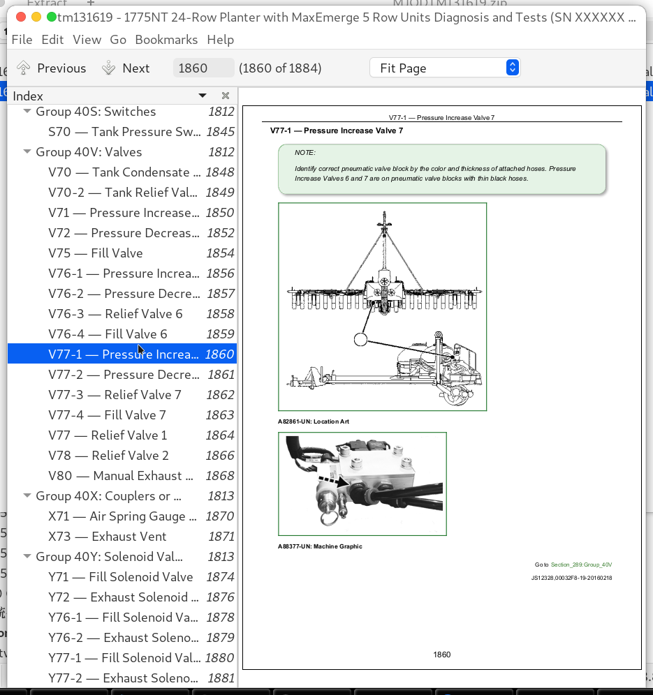
V77-1 — Pressure Increase Valve 7......1860
V77-2 — Pressure Decrease Valve 7......1861
V77-3 — Relief Valve 7......1862
V77-4 — Fill Valve 7......1863
V77 — Relief Valve 1......1864
V78 — Relief Valve 2......1866
V80 — Manual Exhaust Valve......1868
Group 40X: Couplers or Diagnostic Receptacles......1813
X71 — Air Spring Gauge Coupler......1870
X73 — Exhaust Vent......1871
Group 40Y: Solenoid Valves......1813
Y71 — Fill Solenoid Valve......1874
Y72 — Exhaust Solenoid Valve......1876
Y76-1 — Fill Solenoid Valve 6......1878
Y76-2 — Exhaust Solenoid Valve 6......1879
Y77-1 — Fill Solenoid Valve 7......1880
Y77-2 — Exhaust Solenoid Valve 7......1881
John Deere 1775NT 24-Row Planter with MaxEmerge 5 Row Units Diagnosis and Tests Service Technical Manual (TM131619)
![]()